EP2195559B1 - Dispositif de changement de vitesses à système de servo-assistance - Google Patents
Dispositif de changement de vitesses à système de servo-assistance Download PDFInfo
- Publication number
- EP2195559B1 EP2195559B1 EP08804948.1A EP08804948A EP2195559B1 EP 2195559 B1 EP2195559 B1 EP 2195559B1 EP 08804948 A EP08804948 A EP 08804948A EP 2195559 B1 EP2195559 B1 EP 2195559B1
- Authority
- EP
- European Patent Office
- Prior art keywords
- pin
- power assistance
- assistance device
- hollow shaft
- shifting apparatus
- Prior art date
- Legal status (The legal status is an assumption and is not a legal conclusion. Google has not performed a legal analysis and makes no representation as to the accuracy of the status listed.)
- Not-in-force
Links
- 230000005540 biological transmission Effects 0.000 claims description 27
- 238000006073 displacement reaction Methods 0.000 description 3
- 238000010276 construction Methods 0.000 description 2
- 238000009434 installation Methods 0.000 description 2
- 230000004913 activation Effects 0.000 description 1
- 230000007935 neutral effect Effects 0.000 description 1
Images

Classifications
-
- F—MECHANICAL ENGINEERING; LIGHTING; HEATING; WEAPONS; BLASTING
- F16—ENGINEERING ELEMENTS AND UNITS; GENERAL MEASURES FOR PRODUCING AND MAINTAINING EFFECTIVE FUNCTIONING OF MACHINES OR INSTALLATIONS; THERMAL INSULATION IN GENERAL
- F16H—GEARING
- F16H61/00—Control functions within control units of change-speed- or reversing-gearings for conveying rotary motion ; Control of exclusively fluid gearing, friction gearing, gearings with endless flexible members or other particular types of gearing
- F16H61/26—Generation or transmission of movements for final actuating mechanisms
- F16H61/28—Generation or transmission of movements for final actuating mechanisms with at least one movement of the final actuating mechanism being caused by a non-mechanical force, e.g. power-assisted
- F16H61/30—Hydraulic or pneumatic motors or related fluid control means therefor
-
- F—MECHANICAL ENGINEERING; LIGHTING; HEATING; WEAPONS; BLASTING
- F16—ENGINEERING ELEMENTS AND UNITS; GENERAL MEASURES FOR PRODUCING AND MAINTAINING EFFECTIVE FUNCTIONING OF MACHINES OR INSTALLATIONS; THERMAL INSULATION IN GENERAL
- F16H—GEARING
- F16H61/00—Control functions within control units of change-speed- or reversing-gearings for conveying rotary motion ; Control of exclusively fluid gearing, friction gearing, gearings with endless flexible members or other particular types of gearing
- F16H61/26—Generation or transmission of movements for final actuating mechanisms
- F16H61/28—Generation or transmission of movements for final actuating mechanisms with at least one movement of the final actuating mechanism being caused by a non-mechanical force, e.g. power-assisted
- F16H61/30—Hydraulic or pneumatic motors or related fluid control means therefor
- F16H2061/301—Hydraulic or pneumatic motors or related fluid control means therefor for power assistance, i.e. servos with follow up action
-
- F—MECHANICAL ENGINEERING; LIGHTING; HEATING; WEAPONS; BLASTING
- F16—ENGINEERING ELEMENTS AND UNITS; GENERAL MEASURES FOR PRODUCING AND MAINTAINING EFFECTIVE FUNCTIONING OF MACHINES OR INSTALLATIONS; THERMAL INSULATION IN GENERAL
- F16H—GEARING
- F16H61/00—Control functions within control units of change-speed- or reversing-gearings for conveying rotary motion ; Control of exclusively fluid gearing, friction gearing, gearings with endless flexible members or other particular types of gearing
- F16H61/26—Generation or transmission of movements for final actuating mechanisms
- F16H61/28—Generation or transmission of movements for final actuating mechanisms with at least one movement of the final actuating mechanism being caused by a non-mechanical force, e.g. power-assisted
- F16H61/30—Hydraulic or pneumatic motors or related fluid control means therefor
- F16H2061/301—Hydraulic or pneumatic motors or related fluid control means therefor for power assistance, i.e. servos with follow up action
- F16H2061/302—Hydraulic or pneumatic motors or related fluid control means therefor for power assistance, i.e. servos with follow up action with variable force amplification, e.g. force is depending on selected gear or on actuator force (non-linear amplification)
Definitions
- the invention relates to a switching device with power assistance device according to the closer defined in the preamble of claim 1.
- pneumatic switching aids in dissolved construction consist of a mechanical-pneumatic control part and a separate pneumatic power part.
- a switching aid in dissolved construction is off Loomann; Gear transmission; 2nd Edition; Springer Verlag; 1988; P. 225 known.
- the control part is a mechanically operated control valve, which is actuated by the shift linkage. The transmission of the selection movement during the gear change happens mechanically directly to the transmission. In the transmission of the switching movement, the control valve is actuated and at the same time the manual switching force is transmitted mechanically via a lever to the transmission.
- the manual switching force is additionally supported pneumatically by a pneumatic cylinder. This air cylinder forms as a two-position cylinder with integrated hydraulic damper the pneumatic power unit. A direct proportional representation of the manual switching force is not achieved here.
- the paths between control unit and power unit are long and the installation is space consuming.
- the DE 10 2004 041 543 A1 discloses a shifting device with power assist device for a transmission of a motor vehicle, which comprises a central control shaft whose axial displacement in a selection movement and the rotational movement results in a switching movement.
- a control valve of the power assistance device is activated via pins for transmitting the manual switching force and a lever operatively connected to the pins.
- the pins for transmitting the manual switching force engage in longitudinal grooves in the circumference of the switching shaft and are arranged in the longitudinal grooves such that an axial displacement of the switching shaft is made possible.
- corresponding transverse grooves are provided on the longitudinal grooves.
- a generic switching device with a power assistance device for a transmission of a vehicle which comprises means for switching and selecting a gear stage of a transmission and a control rod of the power assistance device, which acts to be supported a manual shift force.
- Elastic elements are provided in the shifting device to alter or limit the manual shifting force applied to the power assisting device prior to being introduced into the power assisting device.
- the DE 10 2006 006 652 A1 also discloses a shifting apparatus having a power assisting device for a transmission of a vehicle, which comprises means for shifting and selecting a gear stage of a transmission and a control rod of the power assisting device to which a manual shifting force to be assisted acts.
- Spring elements are provided in the shifting device to change the manual shifting force acting on the power assisting device within the power assisting device before and / or during the generation of the power assisting force.
- the present invention has for its object to present an embodiment of a switching device with power assistance device, with which a device for limiting the power assistance force can be optimized.
- the object underlying the invention is achieved by a, including the characterizing features of the main claim having, generic switching device with power assistance device.
- the inventive switching device with power assistance device in particular for transmission of commercial vehicles, comprises a switch housing, means for selecting and switching a gear ratio of the transmission and a transmission point for transmitting the manual shift force to the power assistance device.
- the transfer point for transmitting the manual shift force has a lever which is connected to an element of the power assist device.
- the switching device comprises a device for limiting the power assisting force, which is arranged immediately adjacent to the transmission point for transmitting the manual switching force to the power assistance device and comprises a arranged in the switching shaft pin which engages in at least one groove surrounding the switching shaft hollow shaft, wherein by the in the groove of the hollow shaft engaging pin a limitation of the power assistance force is realized.
- the pin is arranged in the shift shaft such that movement of the shift shaft causes immediate movement of the pin.
- the pin is free of play or arranged with minimal play in the shift shaft.
- the groove in the hollow shaft is designed such that different Vermosemployed between the pin, which is arranged in the switching shaft and engages in the groove of the hollow shaft, and the hollow shaft prevail.
- the torsional backlashes can be designed, for example, such that for each alley or for each gear stage another torsional backlash prevails, whereby a different limitation of the power assisting force for each alley or for each gear ratio can be realized.
- the VerFEemployed at smaller gear ratios are designed to be greater than at higher gear ratios, whereby a larger power assistance force is provided for the smaller gear ratios, as for the larger gear ratios of the transmission.
- the gear stage 3 is here understood by a smaller gear, for example, the gear 2 and a larger gear, for example, the gear 4.
- the hollow shaft in the region of the pin for limiting the power assistance force on a second groove which is offset in the hollow shaft by 180 degrees, that is the first groove opposite, is arranged.
- the pin for limiting the power assisting force is in this case designed and arranged in the switching shaft, that it engages in both the first and in the second groove of the hollow shaft, whereby the load occurring is distributed to the two grooves of the hollow shaft.
- the contact surfaces of the pin for limiting the servo-assisting force and the hollow shaft are designed such that upon contact of the pin with the hollow shaft an optimized surface pressure can be achieved.
- the contact surfaces of pin and hollow shaft are conical to each other.
- the pin is designed to limit the power assistance force in the hollow shaft as a stepped pin, creating two contact points between the pin and the hollow shaft.
- an axial securing of the pin for limiting the power assisting force along its longitudinal axis by the switch housing is realized.
- the pin for limiting the power assisting force can be fixed by at least one securing ring and / or a collar on the pin in the switching shaft.
- the element to which the manual switching force to be assisted acts as a control rod of the servo-assisting device.
- a limitation of the servo-assisting force can be realized by a device for limiting the servo-assisting force for each gear stage or each lane, which is arranged directly next to the transmission point for transmitting the manual shifting force to the servo-assistance device.
- the inventive arrangement the problem of occurring tolerances can be kept correspondingly small, whereby the VerFEemployed between the pin, which is arranged in the shift shaft and engages in the groove of the hollow shaft, and the hollow shaft can be accurately represented and thus the servo-assisting force very precisely on the desired value can be limited.
- the Fig. 1 shows a schematic of a switchgear 2 of a motor vehicle according to the prior art, From a shift lever 4 leads from a shift lever 6 via a lever deflection 8 to a switching device 11 with a pneumatic power assistance device 10.
- the pneumatic Power assistance device 10 has a connecting line 12, which leads to a reservoir 14, from which the pneumatic power assistance device 10 is supplied with compressed air.
- the lever deflection 8 has a first lever 16, which is preferably articulated to the shift rod 6.
- the lever deflection 8 has a second lever 18, which in turn engages in a control rod 20 which is arranged in the pneumatic power assistance device 10.
- a piston rod 22 is provided, in which a lever 24 engages, which is connected via a rotatable switching shaft 26 with a lever 28 in the vehicle transmission 30.
- the lever 28 engages in a shift rail 32 through which gear ratios of the transmission can be switched in a known manner.
- a movement of the lever 24 is transmitted via the switching shaft 26 in a movement of the lever 28, so that the lever 28 can put the shift rail 32 in an axial movement.
- the shift rail 32 preferably assumes three positions, two axial end positions, each corresponding to a switched gear ratio and lying between the end positions center position corresponding to a neutral position of the transmission.
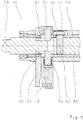
- the Fig. 2 shows the inventive switching device 40 in a sectional view.
- the switching device 40 comprises a central switching shaft 36 which is rotatably mounted within a hollow shaft 38 about its axis 58.
- the switching shaft 36 has at its periphery in the longitudinal direction, ie along the axis 58, longitudinal grooves 50, engage in the pins 34 for transmitting the manual switching force, which in turn are arranged in a lever 18, preferably rotatably mounted in needle bushings.
- the pins 34 are arranged in the grooves 50, that an axial displacement of the switching shaft 36, ie the selection movement is possible, wherein a rotation of the switching shaft 36 about the axis 58 to a pivoting of the lever 18 leads, resulting in an activation of the Servo-assisting device 10 leads, since the lever 18 engages in the control rod 20, not shown here, of the power assistance device 10 (please refer Fig. 1 ).
- the power assisting force generated by the power assisting device 10 is transmitted to the lever 24 from the piston rod 22 (not shown) (see FIG Fig. 1 ).
- the lever 24 is rotatably connected to the hollow shaft 38, whereby the servo-assisting force generated by the power assist device 10 is transmitted via the lever 24 to the hollow shaft 38.
- the hollow shaft 38 is axially fixed in the switching device and arranged rotatably with the switching shaft 36 for switching the shift rails 32.
- the switching device 40 comprises a device for limiting the power assistance force, which is arranged immediately adjacent to the transfer point for transmitting the manual shift force to the power assistance device 10, ie immediately adjacent to the lever 18 in which the pins 34 are arranged, which in the grooves 50 engage the shift shaft 36.
- the device for limiting the power assisting force comprises a pin 42 arranged in the switching shaft 36, which engages here in a groove 46 of the hollow shaft 38.
- the groove 46 in the hollow shaft 38 is in this case designed such that prevail between the groove 46 and the pin 42 and thus between the hollow shaft 38 and the switching shaft 36 corresponding Verwindieri.
- the power assistance force can be limited accordingly for each lane or grade.
- the servo-assisting force limiting pin 42 arranged in the switching shaft 36 is arranged symmetrically with respect to the groove 50 in the switching shaft 36 and thus symmetrically with respect to the pins 34 for transmitting the manual shifting force to the power assisting device 10.
- An axial securing of the pin 42 along its longitudinal axis is realized here by the switch housing 44.
- the shift shaft 36 can be rotatably operated to transmit the manual shift force to the triggering lever 18 of the power assist device 10 and to transmit the manual shift force to the shift rails 32nd Furthermore, the shift shaft 36 can be actuated axially to select the shift rail 32 to be shifted, ie for the selection movement.
- the Fig. 3 shows the switching shaft 36, the hollow shaft 38, which surrounds the switching shaft 36, the groove 46 in the hollow shaft 38, the pin 42 which engages in the groove 46 and is arranged in the switching shaft 36, the lever 24, the rotationally fixed to the hollow shaft 38 is connected and the lever 18, which via pins 34 (see Fig. 2 ) is in communication with the switching shaft 36.
- the pin 42 is indicated in the groove 46 in three different positions, but it is in the groove 46 only once available.
- the in the Fig. 3 left position represents the position of the pin 42 in the alley 52 for the gear ratio 3/4 of a vehicle transmission.
- the middle position represents the position of the pin 42 in the alley 54 for the ratio 1/2, while the right position, the position of Pin 42 in the alley 56 for the R-course and / or crawler gear represents.
- the groove 46 in the hollow shaft 38 is formed such that different VerFDteil s1 - s6 prevail between the pin 42 and the hollow shaft 38.
- the groove 46 shown here is designed such that in the lane 54, a larger backlash s1, s2 prevails, as in the alley 52 (backlash s3, s4).
- the power assisting force is generated until the torsional backlash s1 - s6 between the pin 42 and the hollow shaft 38 and thus between the switching shaft 36 and the hollow shaft 38 is canceled.
- the manual switching force is transmitted directly to the hollow shaft 38 and the control rod 20 of the power assistance device 10 makes relative to the piston rod 22 of the power assistance device 10 no way.
- the VerFDieri s1 - s6 are designed to be larger at lower gear ratios than at higher gear ratios, a larger power assistance force can be provided for the smaller gear ratios, as for the larger gear ratios.
- the power assisting force can be limited by the VerFDieri s5, s6 accordingly.
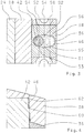
- the Fig. 4 shows the pin 42, which is arranged in the switching shaft 36 and engages in the groove 46 of the hollow shaft 38.
- the pin 42 is designed here in stepped form, whereby two contact points 60, 62 between the pin 42 and the hollow shaft 38 arise. Upon rotation of the pin 42 by the switching shaft 36, this comes first with the contact point 60 with the hollow shaft 38 in contact. Occurs at the contact point 60, for example, a wear, then comes with a rotation of the pin 42 now also the contact point 62 with the hollow shaft 38 in contact.
- an optimized surface pressure between the pin 42 and the hollow shaft 38 can be realized.
Landscapes
- Engineering & Computer Science (AREA)
- General Engineering & Computer Science (AREA)
- Mechanical Engineering (AREA)
- Gear-Shifting Mechanisms (AREA)
Claims (9)
- Dispositif de changement de vitesse (11, 40) à système de servo-assistance (10) pour une boîte de vitesses (30) d'un véhicule, avec un carter de changement de vitesse (44), avec des moyens de sélection et de changement d'étage de transmission de la boîte de vitesses (30), avec un point de transmission pour la transmission de la force de changement de vitesse de la main au système de servo-assistance (10) et avec des moyens pour changer et/ou limiter la force de changement de vitesse de la main agissant sur le système de servo-assistance (10), le point de transmission de la force de changement de vitesse de la main comportant un levier (18) relié à un élément (20) du système de servo-assistance (10), caractérisé en ce que le dispositif de changement de vitesse (11, 40) comporte un dispositif de limitation de la force de servo-assistance disposé directement à côté du levier (18) du point de transmission pour transmettre la force de changement de vitesse de la main au système de servo-assistance (10) et qu'il comprend une tige (42) disposée dans l'arbre de changement de vitesse (36) s'engrenant dans au moins une rainure (46) d'un arbre creux (38) entourant l'arbre de changement de vitesse (36) et la rainure (46) étant réalisée de telle sorte dans l'arbre creux (38) que différents jeux de torsion (s1 - s6) sont possibles entre la tige (42) et l'arbre creux (38).
- Dispositif de changement de vitesse (11, 40) à système de servo-assistance (10) selon la revendication 1, caractérisé en ce que les jeux de torsion (s1 - s6) sont réalisés de façon à être plus importants pour les plus petits étages de transmission que pour les plus grands étages de transmission, mettant à disposition une force de servo-assistance plus grande pour les plus petits étages de transmission que pour les plus grands étages de transmission.
- Dispositif de changement de vitesse (11, 40) à système de servo-assistance (10) selon au moins l'une quelconque des revendications précédentes, caractérisé en ce que l'arbre creux (38) comporte, dans la région de la tige (42), une deuxième rainure disposée de façon décalée de 180 degrés par rapport à la rainure (46) dans l'arbre creux (38) et la tige (42) étant réalisée et disposée de telle sorte dans l'arbre de changement de vitesse (36) qu'elle s'engrène tant dans la rainure (46) que dans la deuxième rainure de l'arbre creux (38) .
- Dispositif de changement de vitesse (11, 40) à système de servo-assistance (10) selon au moins l'une quelconque des revendications précédentes, caractérisé en ce que les surfaces de contact de la tige (42) et de l'arbre creux (38) sont réalisées de telle sorte qu'une pression superficielle optimisée peut être obtenue en cas de contact.
- Dispositif de changement de vitesse (11, 40) à système de servo-assistance (10) selon la revendication 4, caractérisé en ce que les surfaces de contact de la tige (42) et de l'arbre creux (38) sont réalisées de façon conique l'une par rapport à l'autre.
- Dispositif de changement de vitesse (11, 40) à système de servo-assistance (10) selon la revendication 4, caractérisé en ce que la tige (42) située dans la région de l'arbre creux (38) est réalisée sous la forme d'une tige décalée, provoquant la création de deux points d'appui (60,62) entre la tige (42) et l'arbre creux (38).
- Dispositif de changement de vitesse (11, 40) à système de servo-assistance (10) selon au moins l'une quelconque des revendications précédentes, caractérisé en ce qu'une fixation axiale de la tige (42) peut être réalisée le long de son axe longitudinal par le carter de changement de vitesse (44).
- Dispositif de changement de vitesse (11, 40) à système de servo-assistance (10) selon au moins l'une quelconque des revendications 1 à 6, caractérisé en ce qu'une fixation axiale de la tige (42) le long de son axe longitudinal peut être réalisée par au moins une bague de fixation et/ou un lien prévu au niveau de la tige (42).
- Dispositif de changement de vitesse (11, 40) à système de servo-assistance (10) selon au moins l'une quelconque des revendications précédentes, caractérisé en ce que l'élément (20) est réalisé sous la forme d'une tige de commande du système de servo-assistance (10) .
Applications Claiming Priority (2)
| Application Number | Priority Date | Filing Date | Title |
|---|---|---|---|
| DE102007048401A DE102007048401A1 (de) | 2007-10-09 | 2007-10-09 | Schaltvorrichtung mit Servounterstützungseinrichtung |
| PCT/EP2008/063124 WO2009047180A1 (fr) | 2007-10-09 | 2008-10-01 | Dispositif de changement de vitesses à système de servo-assistance |
Publications (2)
| Publication Number | Publication Date |
|---|---|
| EP2195559A1 EP2195559A1 (fr) | 2010-06-16 |
| EP2195559B1 true EP2195559B1 (fr) | 2017-11-22 |
Family
ID=40227580
Family Applications (1)
| Application Number | Title | Priority Date | Filing Date |
|---|---|---|---|
| EP08804948.1A Not-in-force EP2195559B1 (fr) | 2007-10-09 | 2008-10-01 | Dispositif de changement de vitesses à système de servo-assistance |
Country Status (7)
| Country | Link |
|---|---|
| EP (1) | EP2195559B1 (fr) |
| JP (1) | JP5417333B2 (fr) |
| CN (1) | CN101821533B (fr) |
| BR (1) | BRPI0818653A2 (fr) |
| DE (1) | DE102007048401A1 (fr) |
| RU (1) | RU2010118015A (fr) |
| WO (1) | WO2009047180A1 (fr) |
Families Citing this family (1)
| Publication number | Priority date | Publication date | Assignee | Title |
|---|---|---|---|---|
| CN115182992B (zh) * | 2022-06-20 | 2023-11-07 | 陕西法士特齿轮有限责任公司 | 一种调整变速器挂挡助力结构 |
Family Cites Families (7)
| Publication number | Priority date | Publication date | Assignee | Title |
|---|---|---|---|---|
| DE19539471A1 (de) * | 1995-10-24 | 1997-04-30 | Zahnradfabrik Friedrichshafen | Schaltvorrichtung für Kraftfahrzeug-Wechselgetriebe - Pneumatischer Schaltservo - |
| DE19839850B4 (de) * | 1998-09-02 | 2010-01-28 | Zf Friedrichshafen Ag | Schaltvorrichtung für Kraftfahrzeug-Wechselgetriebe |
| DE19840052A1 (de) * | 1998-09-02 | 2000-03-09 | Zahnradfabrik Friedrichshafen | Schaltvorrichtung für Kraftfahrzeug-Wechselgetriebe |
| DE102004041543A1 (de) | 2004-08-27 | 2006-03-02 | Zf Friedrichshafen Ag | Schaltvorrichtung für das Getriebe eines Kraftfahrzeugs |
| DE102006006652A1 (de) | 2006-02-14 | 2007-08-30 | Zf Friedrichshafen Ag | Schaltvorrichtung für Kraftfahrzeug-Wechselgetriebe |
| DE102006006651A1 (de) * | 2006-02-14 | 2007-08-16 | Zf Friedrichshafen Ag | Schaltvorrichtung für Kraftfahrzeug-Wechselgetriebe |
| DE102006042211A1 (de) * | 2006-09-08 | 2008-03-27 | Zf Friedrichshafen Ag | Schaltvorrichtung für Kraftfahrzeug-Wechselgetriebe |
-
2007
- 2007-10-09 DE DE102007048401A patent/DE102007048401A1/de not_active Withdrawn
-
2008
- 2008-10-01 RU RU2010118015/11A patent/RU2010118015A/ru unknown
- 2008-10-01 CN CN2008801110529A patent/CN101821533B/zh not_active Expired - Fee Related
- 2008-10-01 BR BRPI0818653A patent/BRPI0818653A2/pt not_active IP Right Cessation
- 2008-10-01 JP JP2010528364A patent/JP5417333B2/ja not_active Expired - Fee Related
- 2008-10-01 WO PCT/EP2008/063124 patent/WO2009047180A1/fr not_active Ceased
- 2008-10-01 EP EP08804948.1A patent/EP2195559B1/fr not_active Not-in-force
Also Published As
| Publication number | Publication date |
|---|---|
| RU2010118015A (ru) | 2011-11-20 |
| CN101821533A (zh) | 2010-09-01 |
| CN101821533B (zh) | 2013-07-24 |
| JP2010540876A (ja) | 2010-12-24 |
| JP5417333B2 (ja) | 2014-02-12 |
| DE102007048401A1 (de) | 2009-04-16 |
| WO2009047180A1 (fr) | 2009-04-16 |
| EP2195559A1 (fr) | 2010-06-16 |
| BRPI0818653A2 (pt) | 2016-06-21 |
Similar Documents
| Publication | Publication Date | Title |
|---|---|---|
| EP2220404B1 (fr) | Dispositif d'assistance pour boite de vitesses de vehicule automobile | |
| DE19902556B4 (de) | Lenkgetrieb mit redundantem Antrieb | |
| EP2153089B1 (fr) | Dispositif de changement de vitesse pour une boîte de vitesses d'un véhicule à moteur | |
| WO2000014437A1 (fr) | Dispositif de commande de boites de vitesses de vehicules | |
| EP2076695B1 (fr) | Système de servo-assistance pour une boîte de vitesses de véhicule automobile | |
| WO2007101754A1 (fr) | Dispositif de changement de vitesse pour une boîte de vitesses de véhicule automobile | |
| EP2156059B1 (fr) | Système de servo-assistance | |
| EP1836419B1 (fr) | Dispositif de commutation pour boite de vitesses et utilisation d'un tel dispositif de commutation | |
| DE102007052460A1 (de) | Wählhebel einer Betätigungseinrichtung für ein Kraftfahrzeug-Wechselgetriebe | |
| DE102005060933B3 (de) | Wählhebel, insbesondere für ein Kraftfahrzeug | |
| EP2068044B1 (fr) | Système de servo-assistance pour une boîte de vitesses de véhicule automobile | |
| EP1291560B1 (fr) | Dispositif de changement de rapports à commande assistée | |
| EP2059695B1 (fr) | Dispositif de changement de vitesse pour une boîte de vitesses de véhicule automobile | |
| EP2195559B1 (fr) | Dispositif de changement de vitesses à système de servo-assistance | |
| EP1630460B1 (fr) | Dispositif de changement de vitesses pour la transmission d'un véhicule automobile | |
| DE10234596B3 (de) | Als Kugelumlauflenkung ausgebildete elektrische Servolenkung eines Kraftfahrzeuges | |
| EP2222531A1 (fr) | Servosoupape pour une direction assistee hydraulique | |
| DE10232873A1 (de) | Elektromechanischer Getriebesteller | |
| DE10350938A1 (de) | Elektromechanischer Getriebesteller | |
| DE102004037994A1 (de) | Verbindung zwischen Rastenscheibe und Verbindungsstange bei einer Parksperre für ein Kraftfahrzeug | |
| WO2017080720A1 (fr) | Ensemble servant à actionner au moins un élément de passage de vitesse | |
| DE102020109952A1 (de) | Lenk-Bedieneinheit mit kompakt verstaubarem Stellantrieb | |
| EP1058639B1 (fr) | Vanne de distribution rotative destinee a des directions assistees de vehicules | |
| EP3187753B1 (fr) | Dispositif de levier de sélection de vitesse destiné à sélectionner ou changer les rapports d'une boîte de vitesses manuelle d'un véhicule automobile | |
| DE102016214707A1 (de) | Gangwahlhebel für ein Fahrzeuggetriebe |
Legal Events
| Date | Code | Title | Description |
|---|---|---|---|
| PUAI | Public reference made under article 153(3) epc to a published international application that has entered the european phase |
Free format text: ORIGINAL CODE: 0009012 |
|
| 17P | Request for examination filed |
Effective date: 20100309 |
|
| AK | Designated contracting states |
Kind code of ref document: A1 Designated state(s): AT BE BG CH CY CZ DE DK EE ES FI FR GB GR HR HU IE IS IT LI LT LU LV MC MT NL NO PL PT RO SE SI SK TR |
|
| AX | Request for extension of the european patent |
Extension state: AL BA MK RS |
|
| DAX | Request for extension of the european patent (deleted) | ||
| 17Q | First examination report despatched |
Effective date: 20130409 |
|
| GRAP | Despatch of communication of intention to grant a patent |
Free format text: ORIGINAL CODE: EPIDOSNIGR1 |
|
| INTG | Intention to grant announced |
Effective date: 20170529 |
|
| GRAS | Grant fee paid |
Free format text: ORIGINAL CODE: EPIDOSNIGR3 |
|
| GRAA | (expected) grant |
Free format text: ORIGINAL CODE: 0009210 |
|
| AK | Designated contracting states |
Kind code of ref document: B1 Designated state(s): AT BE BG CH CY CZ DE DK EE ES FI FR GB GR HR HU IE IS IT LI LT LU LV MC MT NL NO PL PT RO SE SI SK TR |
|
| REG | Reference to a national code |
Ref country code: GB Ref legal event code: FG4D Free format text: NOT ENGLISH |
|
| REG | Reference to a national code |
Ref country code: CH Ref legal event code: EP |
|
| REG | Reference to a national code |
Ref country code: IE Ref legal event code: FG4D Free format text: LANGUAGE OF EP DOCUMENT: GERMAN |
|
| REG | Reference to a national code |
Ref country code: AT Ref legal event code: REF Ref document number: 948718 Country of ref document: AT Kind code of ref document: T Effective date: 20171215 |
|
| REG | Reference to a national code |
Ref country code: DE Ref legal event code: R096 Ref document number: 502008015758 Country of ref document: DE |
|
| REG | Reference to a national code |
Ref country code: NL Ref legal event code: MP Effective date: 20171122 |
|
| REG | Reference to a national code |
Ref country code: LT Ref legal event code: MG4D |
|
| PG25 | Lapsed in a contracting state [announced via postgrant information from national office to epo] |
Ref country code: FI Free format text: LAPSE BECAUSE OF FAILURE TO SUBMIT A TRANSLATION OF THE DESCRIPTION OR TO PAY THE FEE WITHIN THE PRESCRIBED TIME-LIMIT Effective date: 20171122 Ref country code: LT Free format text: LAPSE BECAUSE OF FAILURE TO SUBMIT A TRANSLATION OF THE DESCRIPTION OR TO PAY THE FEE WITHIN THE PRESCRIBED TIME-LIMIT Effective date: 20171122 Ref country code: NL Free format text: LAPSE BECAUSE OF FAILURE TO SUBMIT A TRANSLATION OF THE DESCRIPTION OR TO PAY THE FEE WITHIN THE PRESCRIBED TIME-LIMIT Effective date: 20171122 Ref country code: SE Free format text: LAPSE BECAUSE OF FAILURE TO SUBMIT A TRANSLATION OF THE DESCRIPTION OR TO PAY THE FEE WITHIN THE PRESCRIBED TIME-LIMIT Effective date: 20171122 Ref country code: NO Free format text: LAPSE BECAUSE OF FAILURE TO SUBMIT A TRANSLATION OF THE DESCRIPTION OR TO PAY THE FEE WITHIN THE PRESCRIBED TIME-LIMIT Effective date: 20180222 Ref country code: ES Free format text: LAPSE BECAUSE OF FAILURE TO SUBMIT A TRANSLATION OF THE DESCRIPTION OR TO PAY THE FEE WITHIN THE PRESCRIBED TIME-LIMIT Effective date: 20171122 |
|
| PG25 | Lapsed in a contracting state [announced via postgrant information from national office to epo] |
Ref country code: BG Free format text: LAPSE BECAUSE OF FAILURE TO SUBMIT A TRANSLATION OF THE DESCRIPTION OR TO PAY THE FEE WITHIN THE PRESCRIBED TIME-LIMIT Effective date: 20180222 Ref country code: HR Free format text: LAPSE BECAUSE OF FAILURE TO SUBMIT A TRANSLATION OF THE DESCRIPTION OR TO PAY THE FEE WITHIN THE PRESCRIBED TIME-LIMIT Effective date: 20171122 Ref country code: GR Free format text: LAPSE BECAUSE OF FAILURE TO SUBMIT A TRANSLATION OF THE DESCRIPTION OR TO PAY THE FEE WITHIN THE PRESCRIBED TIME-LIMIT Effective date: 20180223 Ref country code: LV Free format text: LAPSE BECAUSE OF FAILURE TO SUBMIT A TRANSLATION OF THE DESCRIPTION OR TO PAY THE FEE WITHIN THE PRESCRIBED TIME-LIMIT Effective date: 20171122 |
|
| PG25 | Lapsed in a contracting state [announced via postgrant information from national office to epo] |
Ref country code: DK Free format text: LAPSE BECAUSE OF FAILURE TO SUBMIT A TRANSLATION OF THE DESCRIPTION OR TO PAY THE FEE WITHIN THE PRESCRIBED TIME-LIMIT Effective date: 20171122 Ref country code: SK Free format text: LAPSE BECAUSE OF FAILURE TO SUBMIT A TRANSLATION OF THE DESCRIPTION OR TO PAY THE FEE WITHIN THE PRESCRIBED TIME-LIMIT Effective date: 20171122 Ref country code: EE Free format text: LAPSE BECAUSE OF FAILURE TO SUBMIT A TRANSLATION OF THE DESCRIPTION OR TO PAY THE FEE WITHIN THE PRESCRIBED TIME-LIMIT Effective date: 20171122 Ref country code: CY Free format text: LAPSE BECAUSE OF FAILURE TO SUBMIT A TRANSLATION OF THE DESCRIPTION OR TO PAY THE FEE WITHIN THE PRESCRIBED TIME-LIMIT Effective date: 20171122 Ref country code: CZ Free format text: LAPSE BECAUSE OF FAILURE TO SUBMIT A TRANSLATION OF THE DESCRIPTION OR TO PAY THE FEE WITHIN THE PRESCRIBED TIME-LIMIT Effective date: 20171122 |
|
| REG | Reference to a national code |
Ref country code: DE Ref legal event code: R097 Ref document number: 502008015758 Country of ref document: DE |
|
| PG25 | Lapsed in a contracting state [announced via postgrant information from national office to epo] |
Ref country code: IT Free format text: LAPSE BECAUSE OF FAILURE TO SUBMIT A TRANSLATION OF THE DESCRIPTION OR TO PAY THE FEE WITHIN THE PRESCRIBED TIME-LIMIT Effective date: 20171122 Ref country code: PL Free format text: LAPSE BECAUSE OF FAILURE TO SUBMIT A TRANSLATION OF THE DESCRIPTION OR TO PAY THE FEE WITHIN THE PRESCRIBED TIME-LIMIT Effective date: 20171122 Ref country code: RO Free format text: LAPSE BECAUSE OF FAILURE TO SUBMIT A TRANSLATION OF THE DESCRIPTION OR TO PAY THE FEE WITHIN THE PRESCRIBED TIME-LIMIT Effective date: 20171122 |
|
| PG25 | Lapsed in a contracting state [announced via postgrant information from national office to epo] |
Ref country code: MT Free format text: LAPSE BECAUSE OF FAILURE TO SUBMIT A TRANSLATION OF THE DESCRIPTION OR TO PAY THE FEE WITHIN THE PRESCRIBED TIME-LIMIT Effective date: 20171122 |
|
| PLBE | No opposition filed within time limit |
Free format text: ORIGINAL CODE: 0009261 |
|
| STAA | Information on the status of an ep patent application or granted ep patent |
Free format text: STATUS: NO OPPOSITION FILED WITHIN TIME LIMIT |
|
| 26N | No opposition filed |
Effective date: 20180823 |
|
| PG25 | Lapsed in a contracting state [announced via postgrant information from national office to epo] |
Ref country code: SI Free format text: LAPSE BECAUSE OF FAILURE TO SUBMIT A TRANSLATION OF THE DESCRIPTION OR TO PAY THE FEE WITHIN THE PRESCRIBED TIME-LIMIT Effective date: 20171122 |
|
| REG | Reference to a national code |
Ref country code: CH Ref legal event code: PL |
|
| GBPC | Gb: european patent ceased through non-payment of renewal fee |
Effective date: 20181001 |
|
| REG | Reference to a national code |
Ref country code: BE Ref legal event code: MM Effective date: 20181031 |
|
| PG25 | Lapsed in a contracting state [announced via postgrant information from national office to epo] |
Ref country code: MC Free format text: LAPSE BECAUSE OF FAILURE TO SUBMIT A TRANSLATION OF THE DESCRIPTION OR TO PAY THE FEE WITHIN THE PRESCRIBED TIME-LIMIT Effective date: 20171122 Ref country code: LU Free format text: LAPSE BECAUSE OF NON-PAYMENT OF DUE FEES Effective date: 20181001 |
|
| REG | Reference to a national code |
Ref country code: IE Ref legal event code: MM4A |
|
| PG25 | Lapsed in a contracting state [announced via postgrant information from national office to epo] |
Ref country code: CH Free format text: LAPSE BECAUSE OF NON-PAYMENT OF DUE FEES Effective date: 20181031 Ref country code: BE Free format text: LAPSE BECAUSE OF NON-PAYMENT OF DUE FEES Effective date: 20181031 Ref country code: FR Free format text: LAPSE BECAUSE OF NON-PAYMENT OF DUE FEES Effective date: 20181031 Ref country code: LI Free format text: LAPSE BECAUSE OF NON-PAYMENT OF DUE FEES Effective date: 20181031 |
|
| PG25 | Lapsed in a contracting state [announced via postgrant information from national office to epo] |
Ref country code: IE Free format text: LAPSE BECAUSE OF NON-PAYMENT OF DUE FEES Effective date: 20181001 Ref country code: GB Free format text: LAPSE BECAUSE OF NON-PAYMENT OF DUE FEES Effective date: 20181001 |
|
| REG | Reference to a national code |
Ref country code: AT Ref legal event code: MM01 Ref document number: 948718 Country of ref document: AT Kind code of ref document: T Effective date: 20181001 |
|
| PG25 | Lapsed in a contracting state [announced via postgrant information from national office to epo] |
Ref country code: AT Free format text: LAPSE BECAUSE OF NON-PAYMENT OF DUE FEES Effective date: 20181001 |
|
| PG25 | Lapsed in a contracting state [announced via postgrant information from national office to epo] |
Ref country code: TR Free format text: LAPSE BECAUSE OF FAILURE TO SUBMIT A TRANSLATION OF THE DESCRIPTION OR TO PAY THE FEE WITHIN THE PRESCRIBED TIME-LIMIT Effective date: 20171122 |
|
| PG25 | Lapsed in a contracting state [announced via postgrant information from national office to epo] |
Ref country code: PT Free format text: LAPSE BECAUSE OF FAILURE TO SUBMIT A TRANSLATION OF THE DESCRIPTION OR TO PAY THE FEE WITHIN THE PRESCRIBED TIME-LIMIT Effective date: 20171122 |
|
| PG25 | Lapsed in a contracting state [announced via postgrant information from national office to epo] |
Ref country code: HU Free format text: LAPSE BECAUSE OF FAILURE TO SUBMIT A TRANSLATION OF THE DESCRIPTION OR TO PAY THE FEE WITHIN THE PRESCRIBED TIME-LIMIT; INVALID AB INITIO Effective date: 20081001 |
|
| PG25 | Lapsed in a contracting state [announced via postgrant information from national office to epo] |
Ref country code: IS Free format text: LAPSE BECAUSE OF FAILURE TO SUBMIT A TRANSLATION OF THE DESCRIPTION OR TO PAY THE FEE WITHIN THE PRESCRIBED TIME-LIMIT Effective date: 20180322 |
|
| PGFP | Annual fee paid to national office [announced via postgrant information from national office to epo] |
Ref country code: DE Payment date: 20220831 Year of fee payment: 15 |
|
| P01 | Opt-out of the competence of the unified patent court (upc) registered |
Effective date: 20230528 |
|
| REG | Reference to a national code |
Ref country code: DE Ref legal event code: R119 Ref document number: 502008015758 Country of ref document: DE |
|
| PG25 | Lapsed in a contracting state [announced via postgrant information from national office to epo] |
Ref country code: DE Free format text: LAPSE BECAUSE OF NON-PAYMENT OF DUE FEES Effective date: 20240501 |