EP1630917A1 - Système de montage et de connexion pour appareils électriques - Google Patents
Système de montage et de connexion pour appareils électriques Download PDFInfo
- Publication number
- EP1630917A1 EP1630917A1 EP05014282A EP05014282A EP1630917A1 EP 1630917 A1 EP1630917 A1 EP 1630917A1 EP 05014282 A EP05014282 A EP 05014282A EP 05014282 A EP05014282 A EP 05014282A EP 1630917 A1 EP1630917 A1 EP 1630917A1
- Authority
- EP
- European Patent Office
- Prior art keywords
- connection system
- mounting
- assembly
- connector
- connection
- Prior art date
- Legal status (The legal status is an assumption and is not a legal conclusion. Google has not performed a legal analysis and makes no representation as to the accuracy of the status listed.)
- Granted
Links
- 239000004020 conductor Substances 0.000 claims description 11
- 230000000712 assembly Effects 0.000 claims description 10
- 238000000429 assembly Methods 0.000 claims description 10
- 238000003780 insertion Methods 0.000 claims description 6
- 230000037431 insertion Effects 0.000 claims description 6
- 230000007935 neutral effect Effects 0.000 claims description 2
- 238000013461 design Methods 0.000 description 6
- 238000010276 construction Methods 0.000 description 3
- 238000009434 installation Methods 0.000 description 3
- 238000005516 engineering process Methods 0.000 description 2
- 241000722921 Tulipa gesneriana Species 0.000 description 1
- 238000013459 approach Methods 0.000 description 1
- 150000001875 compounds Chemical class 0.000 description 1
- 239000002360 explosive Substances 0.000 description 1
- 230000003993 interaction Effects 0.000 description 1
- 238000000034 method Methods 0.000 description 1
- 238000012549 training Methods 0.000 description 1
Images






Classifications
-
- H—ELECTRICITY
- H01—ELECTRIC ELEMENTS
- H01R—ELECTRICALLY-CONDUCTIVE CONNECTIONS; STRUCTURAL ASSOCIATIONS OF A PLURALITY OF MUTUALLY-INSULATED ELECTRICAL CONNECTING ELEMENTS; COUPLING DEVICES; CURRENT COLLECTORS
- H01R31/00—Coupling parts supported only by co-operation with counterpart
- H01R31/08—Short-circuiting members for bridging contacts in a counterpart
- H01R31/085—Short circuiting bus-strips
-
- H—ELECTRICITY
- H01—ELECTRIC ELEMENTS
- H01R—ELECTRICALLY-CONDUCTIVE CONNECTIONS; STRUCTURAL ASSOCIATIONS OF A PLURALITY OF MUTUALLY-INSULATED ELECTRICAL CONNECTING ELEMENTS; COUPLING DEVICES; CURRENT COLLECTORS
- H01R13/00—Details of coupling devices of the kinds covered by groups H01R12/70 or H01R24/00 - H01R33/00
- H01R13/73—Means for mounting coupling parts to apparatus or structures, e.g. to a wall
-
- H—ELECTRICITY
- H01—ELECTRIC ELEMENTS
- H01R—ELECTRICALLY-CONDUCTIVE CONNECTIONS; STRUCTURAL ASSOCIATIONS OF A PLURALITY OF MUTUALLY-INSULATED ELECTRICAL CONNECTING ELEMENTS; COUPLING DEVICES; CURRENT COLLECTORS
- H01R9/00—Structural associations of a plurality of mutually-insulated electrical connecting elements, e.g. terminal strips or terminal blocks; Terminals or binding posts mounted upon a base or in a case; Bases therefor
- H01R9/22—Bases, e.g. strip, block, panel
-
- H—ELECTRICITY
- H01—ELECTRIC ELEMENTS
- H01R—ELECTRICALLY-CONDUCTIVE CONNECTIONS; STRUCTURAL ASSOCIATIONS OF A PLURALITY OF MUTUALLY-INSULATED ELECTRICAL CONNECTING ELEMENTS; COUPLING DEVICES; CURRENT COLLECTORS
- H01R9/00—Structural associations of a plurality of mutually-insulated electrical connecting elements, e.g. terminal strips or terminal blocks; Terminals or binding posts mounted upon a base or in a case; Bases therefor
- H01R9/22—Bases, e.g. strip, block, panel
- H01R9/28—Terminal boards
-
- H—ELECTRICITY
- H01—ELECTRIC ELEMENTS
- H01R—ELECTRICALLY-CONDUCTIVE CONNECTIONS; STRUCTURAL ASSOCIATIONS OF A PLURALITY OF MUTUALLY-INSULATED ELECTRICAL CONNECTING ELEMENTS; COUPLING DEVICES; CURRENT COLLECTORS
- H01R9/00—Structural associations of a plurality of mutually-insulated electrical connecting elements, e.g. terminal strips or terminal blocks; Terminals or binding posts mounted upon a base or in a case; Bases therefor
- H01R9/22—Bases, e.g. strip, block, panel
- H01R9/24—Terminal blocks
- H01R9/2491—Terminal blocks structurally associated with plugs or sockets
Definitions
- the invention relates to a mounting and connection system for electrical equipment.
- control devices of electrical appliances e.g. in particular for motors, which preferably each have a contactor and a circuit breaker.
- the latter application in three-phase design is the preferred application.
- the invention is also suitable for driving and supplying any other electrical devices, such as for driving circuit breakers or contactors alone (in one, two or otherwise multi-phase training).
- the system further comprises mounting plate pieces for electrical devices which can be applied to the mounting rails, in particular for arranging in each case one of the control devices for motors with one of the contactors and one of the circuit breakers.
- mounting plate pieces for electrical devices which can be applied to the mounting rails, in particular for arranging in each case one of the control devices for motors with one of the contactors and one of the circuit breakers.
- a direct mounting of the devices to be controlled and supplied, for example, is conceivable. on a mounting rail.
- the arrangement with the mounting plate pieces leads to a particularly clear and visually appealing structure.
- all components have connections which are designed as plug-in connections which can be connected in particular without tools.
- connections which are designed as plug-in connections which can be connected in particular without tools.
- direct plug-in connections which are particularly easy and fast tool-less connectable and also relatively uncomplicated entsschaltbar.
- all the components are particularly preferably mounted vertically from the front on the mounting rail or on each other, in particular by being latched on from the front.
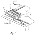
- FIG. 1 shows a perspective view of an assembly and connection system according to the invention in an exemplary structure that can be realized for example in a control cabinet and here for assembly, arrangement and power or voltage supply of control devices for engines, each of which a contactor. 2 and a power switch 3.
- Fig. 1 therefore shows a view from the front of the mounting and connection system, the installation in the cabinet preferably takes place vertically, but is not limited to this mounting position.
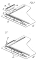
- the mounting device is based on Fig. 2 on a plurality of hat-like support rails 4, 5, 6, which in a conventional manner on a base plate 7 - for example, a control cabinet (not shown here) - can be mounted.
- Two or more of the support rails 4, 5 are aligned and arranged parallel to each other.
- another of the mounting rails 6 is arranged perpendicular to the further mounting rails 4, 5 next to one axial end thereof. In this way, a mounting base is realized on the base plate 7, which can be supplemented in practice by further mounting rails.
- a plurality of so-called connectors 8, 9 for busbars (FIGS. 8-11) and a feed module 34 (FIG. 23) are initially perpendicular to the carrier rails 4, 5, 6 (FIG A), in particular latched (Fig. 2a and b).
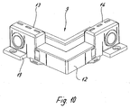
- the connectors 8, 9 each have a one-piece hood 10 which forms two interconnected via a flatter center socket 11 or corner base 12 and relative to the center socket 11 or corner socket 12 higher Aufrastsockel 13,14 which are either aligned with each other - connector 8 (Fig. 8) - or are arranged over the corner - corner connector 9 (Fig. 12).
- the Aufrastsockel 13,14 each have on its front side or on its side facing away from the mounting rail side insertion openings 15 for conductors, through each of which a conductor -. in the manner of a flat connector; see Fig. 14 - in a corresponding plug contact can be inserted (here, for example, a connector receptacle 46 (FIG. 9) as a resilient slot at the end of the busbars 16).
- Fig. 9a shows bus bars 16, which cause a reverse assignment behind the connector. This is avoided with the bus bars 16 'of Fig. 9b crossing so that the occupancy remains the same in front of and behind the connector.
- Fig. 11a shows bus bars 16, which cause a reverse assignment behind the corner. This is in turn avoided with the bus bars 16 'of Fig. 11b, which intersect, so that the occupancy remains the same in front of and behind the corner.
- mounting feet 19 are formed with mounting holes 20, which allow direct mounting on a base plate 7 without mounting rails.
- the connectors 8, 9 and the feeder modules 34 also each have here a lateral attachment plate 21 and a mounting foot assembly 22 for mounting on the mounting rail, which is provided with locking and unlocking means, e.g. a resilient slide, may be provided to easily snap the connector on the support rail and to be able to be solved by this (not shown).
- the mounting base assembly 22 is configured such that an assembly on the mounting rail vertically from the front is possible.
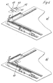
- the preassembled connectors 8, 9 and the feed modules 34 are each configured once or twice with the Aufrastsockeln such that on their Aufrastsockel 13, 14 respectively the axial end portions of one or two busbar assemblies 23 can be placed, in particular latched (Fig. 3).
- bus bar arrangements 23 are placed on them, in particular again vertically latched from the front (arrow A) (FIG. 3).
- the preassembled busbar arrangements 23 each have a hood 31, which can be plugged, in particular latched, via a plastic receiving part with a plurality of conductive busbars 24 (see also FIG. 12).
- the bus bars 24 each comprise at least one or more bus bars 25, on each of which grid-like spaced contact areas 26 are formed, each in the manner of a resilient plug receptacle 27 (e.g., contact tulip) for tabs, e.g. are formed with blade contacts.
- a resilient plug receptacle 27 e.g., contact tulip
- the plug receptacles 27 are each below raster-like slots 28 in the hood 31, which define Aufsteck Schemee 29 with lateral latching contours 30 for the tabs.
- tabs 37 e.g. with arranged thereon knife contacts 38 - Fig. 1, 14a - again inserted from the front, the corresponding lateral latching contours 39 for latching to the latching contours 30 of the hood 31 have.
- the plugs 37 allow a voltage tap by means of fixed conductors 53 or conductors mounted in any connection technique.
- FIG. 14b shows a screw connection by way of example. This option increases the flexibility of the system and its possible applications. This makes it possible, so to speak, the optional further connectivity of one or more devices in any connection technology, if this is necessary.
- the grid and thus the distance of the plug receptacles and the Aufsteck Schemee particular the busbars are optimally designed depending on the purpose in the desired grid.
- the actual conductive bus bars 24 of the busbar assemblies 23 are held in a further plastic receiving portion 48 (Fig. 12) having a lateral projection 49 for aligning the mounting plate pieces 40 (see below to Figs. 4 and 5) and recesses 50, 51 for placement on the Aufrastsockel 13,14 has.
- the hoods 31 of the busbar assemblies are preferably releasably latched onto the connectors 8, 9 ( Figures 3, 7).
- the latching projections 32 are shaped in the manner of buttons or buttons and are designed so large that they can be pressed in by a finger (FIG. 7), the mounting rails can be tool-free snapped onto the connector 8,9 vertically from the front and released from this.
- the corner connector 9 and the feed module are so far constructed in their areas for latching the busbar assemblies 23 analog.
- a hood-like terminal socket 35 for preferably three supplying conductors 36 (e.g. preferably in direct plug-in or, alternatively, e.g. provided in spring or fferan gleichtechnik.
- the connecting base 35 has one of the latching holes 33 and can be plugged as a hood over a Aufrastsockel (Fig. 2 and 3) of the connector 8, 9, which he then contacted (not visible here). On the Aufrastsockel 13 then one end of a busbar assembly 23 are inserted (Fig. 2b), so that 34 busbar arrangements are attached to one or both sides of the feed module.
- bus bar arrangements and the connectors can be designed for three phases as shown here. Alternatively, however, a design for a connection of single-phase devices is conceivable or for two phases or for three phases plus neutral. The number of busbars and connections is adapted to the respective design. It is also conceivable to provide an additional control voltage supply.
- connection for the various phases and / or the busbars of the busbar arrangements not in a row one behind the other but next to each other in several rows 55, 56, 57 (see FIG. 16).
- the connectors and the feed module are designed accordingly.
- a busbar construction can be realized "on the corner" on the two mounting rails 4, 6, from which each location of the further mounting rails arranged in the corner region-here by way of example only a single mounting rail 5-can be easily reached.
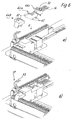
- the surface of the mounting plate pieces 40 is dimensioned in this example and the Aufrastkonturen 43 are designed such that in each case one of the contactors 2 and one of the circuit breaker 3 can be latched. This is illustrated in FIGS. 5a and b. In this way, a defined distance of the motor control components is ensured, which leads to a particularly uniform and clear structure.
- the mounting plate pieces are flush with each other, so that from the connectors and busbars and the mounting plates an optically clean, continuous mounting base is formed.
- the contactors 2 and circuit breaker 3 are provided at their front side (when installed in a control cabinet relative to this installation position) with plug connections, in which in turn vertically from the front pins or blade contacts 45 of connector modules 44 a, b, c are latched, which in each case connect the contacts of contactor 2 and circuit breaker 3 (connection plug-in modules 44a) or circuit breaker 3 and busbar (connection plug-in modules 44b) or the contactor via conductors 54 with motors (connection plug-in modules 44c) (not shown here), so that except for the conductors 54 to the Engines a line-free and also simpler and more compact design is realized.
- the connector plug modules 44a, b, c and / or other of the devices are preferably provided with a device, in particular a slide 52 or a lever, which allows actuation and / or unlocking when the connector module is snapped on.
- a device in particular a slide 52 or a lever, which allows actuation and / or unlocking when the connector module is snapped on.
- An exemplary slider of this kind is shown in FIG. 15.
- all connections are formed as a direct plug-in connections (push-in), which are operated without tools.
- push-in Such a particularly fast production of all compounds is realized. Since otherwise preferably a Aufrastsystem is used for mounting the components and since almost exclusively or even exclusively uniform assembly and Ransteckterrorismen are performed vertically from the front to the mounting rail, the assembly is particularly easy to understand and quick and easy to carry out.
- the bus bar arrangements can have a wide variety of rasters (in particular 9 mm, 18 mm, 27 mm, n * 9 mm).
- plugs 37 are easily plug-in outlets in any connection technology, so in Vietnamese Steck- or e.g. Screwing attached to the busbar arrangements.
- each point on a mounting plate with mounting rails can be supplied with voltage in a simple manner.
- the entry point is freely selectable.
- the components connector, corner connector and feed module can also be attached directly to the mounting plate 7.
- the entire system can be preassembled and then aligned on the mounting plate. A finger safety of all components is ensured even in the "pulled" state.
Landscapes
- Patch Boards (AREA)
- Connector Housings Or Holding Contact Members (AREA)
- Coupling Device And Connection With Printed Circuit (AREA)
- Connections Arranged To Contact A Plurality Of Conductors (AREA)
- Details Of Connecting Devices For Male And Female Coupling (AREA)
Applications Claiming Priority (3)
| Application Number | Priority Date | Filing Date | Title |
|---|---|---|---|
| DE102004041112 | 2004-08-24 | ||
| DE102004062961 | 2004-12-28 | ||
| DE102005003199A DE102005003199A1 (de) | 2004-08-24 | 2005-01-24 | Montage- und Anschluß-System für elektrische Geräte |
Publications (2)
| Publication Number | Publication Date |
|---|---|
| EP1630917A1 true EP1630917A1 (fr) | 2006-03-01 |
| EP1630917B1 EP1630917B1 (fr) | 2007-09-26 |
Family
ID=35262187
Family Applications (1)
| Application Number | Title | Priority Date | Filing Date |
|---|---|---|---|
| EP05014282A Expired - Lifetime EP1630917B1 (fr) | 2004-08-24 | 2005-06-30 | Système de montage et de connexion pour appareils électriques |
Country Status (4)
| Country | Link |
|---|---|
| US (1) | US7408766B2 (fr) |
| EP (1) | EP1630917B1 (fr) |
| AT (1) | ATE374442T1 (fr) |
| DE (2) | DE102005003199A1 (fr) |
Cited By (1)
| Publication number | Priority date | Publication date | Assignee | Title |
|---|---|---|---|---|
| CN101626127B (zh) * | 2008-07-07 | 2012-11-21 | 贵州航天电器股份有限公司 | 带有短路模块及模块锁紧功能的连接器 |
Families Citing this family (12)
| Publication number | Priority date | Publication date | Assignee | Title |
|---|---|---|---|---|
| WO2006122351A1 (fr) * | 2005-05-19 | 2006-11-23 | Telezygology Inc | Glissieres, blocs d'alimentation et de donnees et systeme de fixation liberable |
| US8190664B2 (en) * | 2007-04-26 | 2012-05-29 | International Business Machines Corporation | Employing a mask field of an instruction to encode a sign of a result of the instruction |
| TWM337156U (en) * | 2008-01-11 | 2008-07-21 | Micro Star Int Co Ltd | Composite input/output port electric connector |
| US8547684B2 (en) * | 2009-12-17 | 2013-10-01 | Schneider Electric USA, Inc. | Panelboard having a parallel feeder bars distribution |
| DE202016100307U1 (de) * | 2016-01-22 | 2017-04-26 | Weidmüller Interface GmbH & Co. KG | Reihenbausteinanordnung mit einem Energiebussystem |
| FR3060224B1 (fr) * | 2016-12-14 | 2020-10-02 | Schneider Electric Ind Sas | Installation de distribution electrique a basse tension |
| CN107337020B (zh) * | 2017-08-01 | 2023-04-25 | 常熟市中捷台板厂 | 轨道式滑动接触供电装置的滑车导轨加长连接结构 |
| EP3902074A1 (fr) * | 2020-04-20 | 2021-10-27 | Siemens Aktiengesellschaft | Boîtier de distribution modulaire pour des barres omnibus |
| CN113358907B (zh) * | 2021-07-09 | 2024-09-24 | 浙江双成电气有限公司 | 三相模组化背插式计量装置及其安装方法 |
| US12322916B2 (en) | 2022-06-22 | 2025-06-03 | Ge Aviation Systems Llc | Electronic connection assembly |
| US12368286B2 (en) * | 2022-12-14 | 2025-07-22 | Eaton Intelligent Power Limited | Power sub-feed device |
| US20250149866A1 (en) * | 2023-11-02 | 2025-05-08 | Abb Schweiz Ag | Compact switchboard systems and methods |
Citations (4)
| Publication number | Priority date | Publication date | Assignee | Title |
|---|---|---|---|---|
| EP0112232A1 (fr) * | 1982-12-06 | 1984-06-27 | Hager Electro S.A. | Dispositif d'alimentation ou de pontage pour appareils électriques modulaires juxtaposés |
| US5144530A (en) * | 1989-05-03 | 1992-09-01 | Telemecanique | Power distributor device for electric installations |
| DE19515923A1 (de) * | 1995-05-02 | 1996-11-14 | Woehner Gmbh & Co Kg | Sammelschienen-Adapter |
| EP1003258A1 (fr) * | 1998-10-19 | 2000-05-24 | Framatome Connectors International | Rail de contact comprenant des douilles femelles frontales pour relier entre eux plusieurs rails de contacts |
Family Cites Families (34)
| Publication number | Priority date | Publication date | Assignee | Title |
|---|---|---|---|---|
| US4041257A (en) * | 1976-03-24 | 1977-08-09 | Yancey Leroy D | Cross connect panel for lighting systems |
| US4153318A (en) * | 1977-10-17 | 1979-05-08 | Square D Company | Bus stab for panelboard assembly |
| US4472761A (en) * | 1982-06-18 | 1984-09-18 | Eaton Corporation | Segmented electrical panelboard for industrial frame and residential frame circuit breakers which accepts residential frame circuit breakers at any segment |
| FR2575340B1 (fr) * | 1984-12-20 | 1987-02-06 | Telemecanique Electrique | Systeme et colonne de distribution pour appareils interrupteurs |
| US4713728A (en) * | 1985-02-25 | 1987-12-15 | General Electric Company | Lighting circuit breaker panelboard modular assembly |
| US4631634A (en) * | 1985-02-25 | 1986-12-23 | General Electric Company | Lighting circuit breaker panelboard modular assembly |
| US5120315A (en) * | 1986-11-26 | 1992-06-09 | 501 Baxter International, Inc. | Pressurized fluid dispenser |
| US4752233A (en) * | 1987-07-20 | 1988-06-21 | General Electric Company | Electric power panelboard adapter module |
| US4845592A (en) * | 1987-08-31 | 1989-07-04 | Amp Incorporated | Flexible bussing system for distributing power to printed circuit boards, backplanes or the like |
| US5126918A (en) * | 1989-08-02 | 1992-06-30 | General Electric Company | Electric power distribution panelboard-switchboard assembly |
| EP0434964B1 (fr) * | 1989-11-27 | 1994-04-13 | Bticino S.P.A. | Ensemble d'éléments de construction pour aider la connexion électrique simultanée de plusieurs interrupteurs automatiques modulaires |
| US5067043A (en) * | 1990-12-13 | 1991-11-19 | General Electric Company | Electric power distribution panelboard-switchboard bus bar insulation shield |
| CA2116008A1 (fr) * | 1991-08-20 | 1993-03-04 | Peter William Bowen | Dispositif ameliore de montage de disjoncteurs |
| US5139426A (en) * | 1991-12-11 | 1992-08-18 | Amp Incorporated | Adjunct power connector |
| US5213518A (en) * | 1992-02-28 | 1993-05-25 | Amp Incorporated | Connecting electrical bus bars to electrical circuitry |
| US5196987A (en) * | 1992-03-27 | 1993-03-23 | General Electric Company | Electric busway power take-off assembly |
| US5343356A (en) * | 1992-12-31 | 1994-08-30 | Siemens Energy & Automation, Inc. | Panelboard |
| US5295042A (en) * | 1993-01-06 | 1994-03-15 | General Electric Company | Double branch circuit breaker support |
| US6372989B1 (en) * | 1994-08-31 | 2002-04-16 | Rockwell Automation Ag | Equipment carrier for electric installation equipment |
| DE4438806C1 (de) | 1994-10-31 | 1996-03-21 | Weidmueller Interface | Modulare Steuerungsanlage mit Busleiter |
| DE4438801C1 (de) * | 1994-10-31 | 1996-01-04 | Weidmueller Interface | Modulare Steuerungsanlage |
| DE4440102C1 (de) | 1994-11-10 | 1996-05-15 | Weidmueller Interface | Modulare Steuerungsanlage mit integriertem Feldbusanschluß |
| DE29502186U1 (de) | 1995-02-10 | 1995-03-30 | Weidmüller Interface GmbH & Co, 32760 Detmold | Elektrische Verteileranordnung |
| FR2735290B1 (fr) * | 1995-06-07 | 1997-07-18 | Schneider Electric Sa | Dispositif d'assemblage et de liaison electrique d'appareils modulaires tels des disjoncteurs ou analogues |
| EP0762581B1 (fr) * | 1995-09-04 | 1999-04-07 | Rockwell Automation AG | Dispositif pour fixer un appareil électrique sur un adaptateur |
| DE29802674U1 (de) | 1998-02-17 | 1998-04-16 | Weidmueller Interface | Reihenklemme mit isolationsdurchdringendem Leiteranschluß |
| DE29804284U1 (de) | 1998-03-11 | 1998-05-07 | Weidmüller Interface GmbH & Co, 32760 Detmold | Steuerungsanlage für elektronische Steuerungs- und Automatisierungssysteme |
| DE29806691U1 (de) | 1998-04-15 | 1998-05-28 | Weidmüller Interface GmbH & Co, 32760 Detmold | Montagefuß für anreihbare Einbaugehäuse oder Klemmen |
| US6178106B1 (en) * | 1998-11-03 | 2001-01-23 | Yazaki North America, Inc. | Power distribution center with improved power supply connection |
| DE29901194U1 (de) | 1999-01-25 | 1999-05-20 | Weidmüller Interface GmbH & Co., 32760 Detmold | Busleiterabschnitt für ein elektrisches Gerät |
| US6530811B1 (en) * | 1999-06-04 | 2003-03-11 | Astec International Limited | Modular distribution assembly |
| US6229692B1 (en) * | 1999-06-30 | 2001-05-08 | General Electric Company | Modular circuit breaker and modular lighting panelboard for field assembly |
| DE20211002U1 (de) * | 2002-07-19 | 2003-12-04 | Weidmüller Interface Gmbh & Co. | Modul für ein elektrisches Gerät, insbesondere Feldbusmodul |
| US7298606B2 (en) * | 2004-03-29 | 2007-11-20 | General Electric Company | Apparatus for interfacing remote operated and non-remote operated circuit breakers with an electrical panel |
-
2005
- 2005-01-24 DE DE102005003199A patent/DE102005003199A1/de not_active Withdrawn
- 2005-06-30 EP EP05014282A patent/EP1630917B1/fr not_active Expired - Lifetime
- 2005-06-30 DE DE502005001558T patent/DE502005001558D1/de not_active Expired - Lifetime
- 2005-06-30 AT AT05014282T patent/ATE374442T1/de not_active IP Right Cessation
- 2005-08-18 US US11/206,524 patent/US7408766B2/en not_active Expired - Fee Related
Patent Citations (4)
| Publication number | Priority date | Publication date | Assignee | Title |
|---|---|---|---|---|
| EP0112232A1 (fr) * | 1982-12-06 | 1984-06-27 | Hager Electro S.A. | Dispositif d'alimentation ou de pontage pour appareils électriques modulaires juxtaposés |
| US5144530A (en) * | 1989-05-03 | 1992-09-01 | Telemecanique | Power distributor device for electric installations |
| DE19515923A1 (de) * | 1995-05-02 | 1996-11-14 | Woehner Gmbh & Co Kg | Sammelschienen-Adapter |
| EP1003258A1 (fr) * | 1998-10-19 | 2000-05-24 | Framatome Connectors International | Rail de contact comprenant des douilles femelles frontales pour relier entre eux plusieurs rails de contacts |
Cited By (1)
| Publication number | Priority date | Publication date | Assignee | Title |
|---|---|---|---|---|
| CN101626127B (zh) * | 2008-07-07 | 2012-11-21 | 贵州航天电器股份有限公司 | 带有短路模块及模块锁紧功能的连接器 |
Also Published As
| Publication number | Publication date |
|---|---|
| DE102005003199A1 (de) | 2006-03-02 |
| EP1630917B1 (fr) | 2007-09-26 |
| US7408766B2 (en) | 2008-08-05 |
| DE502005001558D1 (de) | 2007-11-08 |
| ATE374442T1 (de) | 2007-10-15 |
| US20060044739A1 (en) | 2006-03-02 |
Similar Documents
| Publication | Publication Date | Title |
|---|---|---|
| EP1600045B1 (fr) | Support a dispositif d'electrification | |
| DE69017980T2 (de) | Steckdoseneinheit für ein modulares Energieverteilungssystem für Möbel. | |
| DE4438800C1 (de) | Anschlußklemmenblock mit Elektronikmodul | |
| EP1290759B1 (fr) | Borne de connexion | |
| EP1630917B1 (fr) | Système de montage et de connexion pour appareils électriques | |
| WO2014111323A1 (fr) | Ensemble doté d'un module et d'un dispositif électronique | |
| EP2086077A2 (fr) | Système de montage pour composants électriques et/ou mécaniques | |
| DE20114612U1 (de) | Reihenklemme mit Schneidkontakten und Anschlußvorrichtung | |
| EP2497169A2 (fr) | Agencement de montage pour appareils électriques | |
| DE10308389A1 (de) | Rahmengestell mit einer Elektrifiziereinrichtung | |
| EP3644460A2 (fr) | Rail conducteur et système de rails conducteurs | |
| DE102005009856B4 (de) | Anschluss- oder Geräteadapter | |
| DE4001104A1 (de) | Steckverbindung | |
| DE10230292B3 (de) | Träger für Modulgehäuse | |
| DE102012020219B4 (de) | Vorrichtung zum Kontaktieren von elektrischen Leitern und/oder elektrischen Kontaktelementen, sowie Leuchte oder elektrisches Gerät | |
| EP1564848B1 (fr) | Dispositif d'installation avec interface enfichable codable et module supplémentaire correspondant | |
| EP2264470B1 (fr) | Système de raccordement pour compteurs d'électricité | |
| DE10359489A1 (de) | Elektrifiziereinrichtung für ein Rahmengestell eines Schaltschrankes oder Racks | |
| DE69026161T2 (de) | Energieverteilungsvorrichtung für Systemmöbeleinheiten | |
| DE20108460U1 (de) | Modulares Bausatzsystem für eine streckbare elektrische Anschlussvorrichtung und elektrische Anschlussvorrichtung | |
| DE102005023452B4 (de) | Montage- und Verdrahtungssystem für elektrische Funktionsmodule, insbesondere für Schaltgeräte | |
| EP0921611B1 (fr) | Prise et interrupteur pour le secteur | |
| EP1296431A2 (fr) | Ensemble de barres de distribution | |
| DE2116342A1 (de) | Elektrische Steckverbinder | |
| EP2073314B1 (fr) | Agencement de liaison électrique conductrice des conducteurs électriques |
Legal Events
| Date | Code | Title | Description |
|---|---|---|---|
| PUAI | Public reference made under article 153(3) epc to a published international application that has entered the european phase |
Free format text: ORIGINAL CODE: 0009012 |
|
| AK | Designated contracting states |
Kind code of ref document: A1 Designated state(s): AT BE BG CH CY CZ DE DK EE ES FI FR GB GR HU IE IS IT LI LT LU MC NL PL PT RO SE SI SK TR |
|
| AX | Request for extension of the european patent |
Extension state: AL BA HR LV MK YU |
|
| 17P | Request for examination filed |
Effective date: 20060324 |
|
| AKX | Designation fees paid |
Designated state(s): AT BE BG CH CY CZ DE DK EE ES FI FR GB GR HU IE IS IT LI LT LU MC NL PL PT RO SE SI SK TR |
|
| GRAP | Despatch of communication of intention to grant a patent |
Free format text: ORIGINAL CODE: EPIDOSNIGR1 |
|
| GRAS | Grant fee paid |
Free format text: ORIGINAL CODE: EPIDOSNIGR3 |
|
| GRAA | (expected) grant |
Free format text: ORIGINAL CODE: 0009210 |
|
| AK | Designated contracting states |
Kind code of ref document: B1 Designated state(s): AT BE BG CH CY CZ DE DK EE ES FI FR GB GR HU IE IS IT LI LT LU MC NL PL PT RO SE SI SK TR |
|
| REG | Reference to a national code |
Ref country code: GB Ref legal event code: FG4D Free format text: NOT ENGLISH |
|
| REG | Reference to a national code |
Ref country code: CH Ref legal event code: EP |
|
| REF | Corresponds to: |
Ref document number: 502005001558 Country of ref document: DE Date of ref document: 20071108 Kind code of ref document: P |
|
| REG | Reference to a national code |
Ref country code: IE Ref legal event code: FG4D Free format text: LANGUAGE OF EP DOCUMENT: GERMAN |
|
| GBT | Gb: translation of ep patent filed (gb section 77(6)(a)/1977) |
Effective date: 20080102 |
|
| PG25 | Lapsed in a contracting state [announced via postgrant information from national office to epo] |
Ref country code: LT Free format text: LAPSE BECAUSE OF FAILURE TO SUBMIT A TRANSLATION OF THE DESCRIPTION OR TO PAY THE FEE WITHIN THE PRESCRIBED TIME-LIMIT Effective date: 20070926 Ref country code: FI Free format text: LAPSE BECAUSE OF FAILURE TO SUBMIT A TRANSLATION OF THE DESCRIPTION OR TO PAY THE FEE WITHIN THE PRESCRIBED TIME-LIMIT Effective date: 20070926 |
|
| REG | Reference to a national code |
Ref country code: CH Ref legal event code: NV Representative=s name: ISLER & PEDRAZZINI AG |
|
| PG25 | Lapsed in a contracting state [announced via postgrant information from national office to epo] |
Ref country code: PL Free format text: LAPSE BECAUSE OF FAILURE TO SUBMIT A TRANSLATION OF THE DESCRIPTION OR TO PAY THE FEE WITHIN THE PRESCRIBED TIME-LIMIT Effective date: 20070926 |
|
| NLV1 | Nl: lapsed or annulled due to failure to fulfill the requirements of art. 29p and 29m of the patents act | ||
| PG25 | Lapsed in a contracting state [announced via postgrant information from national office to epo] |
Ref country code: GR Free format text: LAPSE BECAUSE OF FAILURE TO SUBMIT A TRANSLATION OF THE DESCRIPTION OR TO PAY THE FEE WITHIN THE PRESCRIBED TIME-LIMIT Effective date: 20071227 Ref country code: NL Free format text: LAPSE BECAUSE OF FAILURE TO SUBMIT A TRANSLATION OF THE DESCRIPTION OR TO PAY THE FEE WITHIN THE PRESCRIBED TIME-LIMIT Effective date: 20070926 Ref country code: ES Free format text: LAPSE BECAUSE OF FAILURE TO SUBMIT A TRANSLATION OF THE DESCRIPTION OR TO PAY THE FEE WITHIN THE PRESCRIBED TIME-LIMIT Effective date: 20080106 |
|
| REG | Reference to a national code |
Ref country code: IE Ref legal event code: FD4D |
|
| PG25 | Lapsed in a contracting state [announced via postgrant information from national office to epo] |
Ref country code: SK Free format text: LAPSE BECAUSE OF FAILURE TO SUBMIT A TRANSLATION OF THE DESCRIPTION OR TO PAY THE FEE WITHIN THE PRESCRIBED TIME-LIMIT Effective date: 20070926 Ref country code: CZ Free format text: LAPSE BECAUSE OF FAILURE TO SUBMIT A TRANSLATION OF THE DESCRIPTION OR TO PAY THE FEE WITHIN THE PRESCRIBED TIME-LIMIT Effective date: 20070926 Ref country code: PT Free format text: LAPSE BECAUSE OF FAILURE TO SUBMIT A TRANSLATION OF THE DESCRIPTION OR TO PAY THE FEE WITHIN THE PRESCRIBED TIME-LIMIT Effective date: 20080226 Ref country code: IS Free format text: LAPSE BECAUSE OF FAILURE TO SUBMIT A TRANSLATION OF THE DESCRIPTION OR TO PAY THE FEE WITHIN THE PRESCRIBED TIME-LIMIT Effective date: 20080126 |
|
| ET | Fr: translation filed | ||
| PG25 | Lapsed in a contracting state [announced via postgrant information from national office to epo] |
Ref country code: SE Free format text: LAPSE BECAUSE OF FAILURE TO SUBMIT A TRANSLATION OF THE DESCRIPTION OR TO PAY THE FEE WITHIN THE PRESCRIBED TIME-LIMIT Effective date: 20071226 Ref country code: RO Free format text: LAPSE BECAUSE OF FAILURE TO SUBMIT A TRANSLATION OF THE DESCRIPTION OR TO PAY THE FEE WITHIN THE PRESCRIBED TIME-LIMIT Effective date: 20070926 |
|
| PG25 | Lapsed in a contracting state [announced via postgrant information from national office to epo] |
Ref country code: DK Free format text: LAPSE BECAUSE OF FAILURE TO SUBMIT A TRANSLATION OF THE DESCRIPTION OR TO PAY THE FEE WITHIN THE PRESCRIBED TIME-LIMIT Effective date: 20070926 |
|
| PLBE | No opposition filed within time limit |
Free format text: ORIGINAL CODE: 0009261 |
|
| STAA | Information on the status of an ep patent application or granted ep patent |
Free format text: STATUS: NO OPPOSITION FILED WITHIN TIME LIMIT |
|
| 26N | No opposition filed |
Effective date: 20080627 |
|
| PG25 | Lapsed in a contracting state [announced via postgrant information from national office to epo] |
Ref country code: IE Free format text: LAPSE BECAUSE OF FAILURE TO SUBMIT A TRANSLATION OF THE DESCRIPTION OR TO PAY THE FEE WITHIN THE PRESCRIBED TIME-LIMIT Effective date: 20070926 |
|
| BERE | Be: lapsed |
Owner name: WEIDMULLER INTERFACE G.M.B.H. & CO. KG Effective date: 20080630 Owner name: ROCKWELL AUTOMATION A.G. Effective date: 20080630 |
|
| PG25 | Lapsed in a contracting state [announced via postgrant information from national office to epo] |
Ref country code: MC Free format text: LAPSE BECAUSE OF NON-PAYMENT OF DUE FEES Effective date: 20080630 |
|
| PG25 | Lapsed in a contracting state [announced via postgrant information from national office to epo] |
Ref country code: BE Free format text: LAPSE BECAUSE OF NON-PAYMENT OF DUE FEES Effective date: 20080630 |
|
| PG25 | Lapsed in a contracting state [announced via postgrant information from national office to epo] |
Ref country code: EE Free format text: LAPSE BECAUSE OF FAILURE TO SUBMIT A TRANSLATION OF THE DESCRIPTION OR TO PAY THE FEE WITHIN THE PRESCRIBED TIME-LIMIT Effective date: 20070926 |
|
| PG25 | Lapsed in a contracting state [announced via postgrant information from national office to epo] |
Ref country code: SI Free format text: LAPSE BECAUSE OF FAILURE TO SUBMIT A TRANSLATION OF THE DESCRIPTION OR TO PAY THE FEE WITHIN THE PRESCRIBED TIME-LIMIT Effective date: 20070926 |
|
| PG25 | Lapsed in a contracting state [announced via postgrant information from national office to epo] |
Ref country code: CY Free format text: LAPSE BECAUSE OF FAILURE TO SUBMIT A TRANSLATION OF THE DESCRIPTION OR TO PAY THE FEE WITHIN THE PRESCRIBED TIME-LIMIT Effective date: 20070926 |
|
| PG25 | Lapsed in a contracting state [announced via postgrant information from national office to epo] |
Ref country code: BG Free format text: LAPSE BECAUSE OF FAILURE TO SUBMIT A TRANSLATION OF THE DESCRIPTION OR TO PAY THE FEE WITHIN THE PRESCRIBED TIME-LIMIT Effective date: 20071226 Ref country code: AT Free format text: LAPSE BECAUSE OF NON-PAYMENT OF DUE FEES Effective date: 20080630 |
|
| PG25 | Lapsed in a contracting state [announced via postgrant information from national office to epo] |
Ref country code: HU Free format text: LAPSE BECAUSE OF FAILURE TO SUBMIT A TRANSLATION OF THE DESCRIPTION OR TO PAY THE FEE WITHIN THE PRESCRIBED TIME-LIMIT Effective date: 20080327 Ref country code: LU Free format text: LAPSE BECAUSE OF NON-PAYMENT OF DUE FEES Effective date: 20080630 |
|
| PG25 | Lapsed in a contracting state [announced via postgrant information from national office to epo] |
Ref country code: TR Free format text: LAPSE BECAUSE OF FAILURE TO SUBMIT A TRANSLATION OF THE DESCRIPTION OR TO PAY THE FEE WITHIN THE PRESCRIBED TIME-LIMIT Effective date: 20070926 |
|
| REG | Reference to a national code |
Ref country code: CH Ref legal event code: PCOW Free format text: NEW ADDRESS: KLINGENBERGSTRASSE 16, 32758 DETMOLD (DE) $ ROCKWELL AUTOMATION AG, INDUSTRIESTRASSE 20, 5000 AARAU (CH) |
|
| REG | Reference to a national code |
Ref country code: CH Ref legal event code: PFA Owner name: WEIDMUELLER INTERFACE GMBH AND CO. KG, CH Free format text: FORMER OWNER: WEIDMUELLER INTERFACE GMBH AND CO. KG, CH |
|
| REG | Reference to a national code |
Ref country code: DE Ref legal event code: R082 Ref document number: 502005001558 Country of ref document: DE Representative=s name: PATENT- UND RECHTSANWAELTE LOESENBECK, SPECHT,, DE Ref country code: DE Ref legal event code: R082 Ref document number: 502005001558 Country of ref document: DE Representative=s name: LOESENBECK UND KOLLEGEN, DE Ref country code: DE Ref legal event code: R081 Ref document number: 502005001558 Country of ref document: DE Owner name: WEIDMUELLER INTERFACE GMBH & CO. KG, DE Free format text: FORMER OWNERS: WEIDMUELLER INTERFACE GMBH & CO. KG, 32758 DETMOLD, DE; ROCKWELL AUTOMATION AG, AARAU, CH Ref country code: DE Ref legal event code: R081 Ref document number: 502005001558 Country of ref document: DE Owner name: ROCKWELL AUTOMATION SWITZERLAND GMBH, CH Free format text: FORMER OWNERS: WEIDMUELLER INTERFACE GMBH & CO. KG, 32758 DETMOLD, DE; ROCKWELL AUTOMATION AG, AARAU, CH |
|
| REG | Reference to a national code |
Ref country code: FR Ref legal event code: PLFP Year of fee payment: 12 |
|
| PGFP | Annual fee paid to national office [announced via postgrant information from national office to epo] |
Ref country code: GB Payment date: 20160621 Year of fee payment: 12 Ref country code: CH Payment date: 20160620 Year of fee payment: 12 |
|
| REG | Reference to a national code |
Ref country code: FR Ref legal event code: CD Owner name: WEIDMUELLER INTERFACE GMBH CO. K Effective date: 20160705 Ref country code: FR Ref legal event code: CJ Effective date: 20160705 Ref country code: FR Ref legal event code: CD Owner name: ROCKWELL AUTOMATION SWITZERLAND GMBH, CH Effective date: 20160705 |
|
| REG | Reference to a national code |
Ref country code: FR Ref legal event code: CA Effective date: 20160708 |
|
| PGFP | Annual fee paid to national office [announced via postgrant information from national office to epo] |
Ref country code: FR Payment date: 20160627 Year of fee payment: 12 |
|
| PGFP | Annual fee paid to national office [announced via postgrant information from national office to epo] |
Ref country code: IT Payment date: 20160628 Year of fee payment: 12 |
|
| REG | Reference to a national code |
Ref country code: CH Ref legal event code: PL |
|
| GBPC | Gb: european patent ceased through non-payment of renewal fee |
Effective date: 20170630 |
|
| REG | Reference to a national code |
Ref country code: FR Ref legal event code: ST Effective date: 20180228 |
|
| PG25 | Lapsed in a contracting state [announced via postgrant information from national office to epo] |
Ref country code: CH Free format text: LAPSE BECAUSE OF NON-PAYMENT OF DUE FEES Effective date: 20170630 Ref country code: GB Free format text: LAPSE BECAUSE OF NON-PAYMENT OF DUE FEES Effective date: 20170630 Ref country code: LI Free format text: LAPSE BECAUSE OF NON-PAYMENT OF DUE FEES Effective date: 20170630 |
|
| PG25 | Lapsed in a contracting state [announced via postgrant information from national office to epo] |
Ref country code: FR Free format text: LAPSE BECAUSE OF NON-PAYMENT OF DUE FEES Effective date: 20170630 Ref country code: IT Free format text: LAPSE BECAUSE OF NON-PAYMENT OF DUE FEES Effective date: 20170630 |
|
| PGFP | Annual fee paid to national office [announced via postgrant information from national office to epo] |
Ref country code: DE Payment date: 20190619 Year of fee payment: 15 |
|
| REG | Reference to a national code |
Ref country code: DE Ref legal event code: R119 Ref document number: 502005001558 Country of ref document: DE |
|
| PG25 | Lapsed in a contracting state [announced via postgrant information from national office to epo] |
Ref country code: DE Free format text: LAPSE BECAUSE OF NON-PAYMENT OF DUE FEES Effective date: 20210101 |