EP1630929A2 - Motorstators - Google Patents
Motorstators Download PDFInfo
- Publication number
- EP1630929A2 EP1630929A2 EP05016776A EP05016776A EP1630929A2 EP 1630929 A2 EP1630929 A2 EP 1630929A2 EP 05016776 A EP05016776 A EP 05016776A EP 05016776 A EP05016776 A EP 05016776A EP 1630929 A2 EP1630929 A2 EP 1630929A2
- Authority
- EP
- European Patent Office
- Prior art keywords
- yoke
- height
- tooth
- stator
- teeth
- Prior art date
- Legal status (The legal status is an assumption and is not a legal conclusion. Google has not performed a legal analysis and makes no representation as to the accuracy of the status listed.)
- Granted
Links
- 238000000034 method Methods 0.000 claims abstract description 21
- XEEYBQQBJWHFJM-UHFFFAOYSA-N Iron Chemical compound [Fe] XEEYBQQBJWHFJM-UHFFFAOYSA-N 0.000 claims abstract description 17
- 238000004663 powder metallurgy Methods 0.000 claims abstract description 14
- 229910000976 Electrical steel Inorganic materials 0.000 claims description 12
- 238000000926 separation method Methods 0.000 claims description 3
- 239000000463 material Substances 0.000 claims description 2
- 238000004519 manufacturing process Methods 0.000 abstract description 14
- 230000000694 effects Effects 0.000 abstract description 8
- 210000003739 neck Anatomy 0.000 description 23
- 230000003247 decreasing effect Effects 0.000 description 3
- 230000004907 flux Effects 0.000 description 2
- 230000008569 process Effects 0.000 description 2
- RYGMFSIKBFXOCR-UHFFFAOYSA-N Copper Chemical compound [Cu] RYGMFSIKBFXOCR-UHFFFAOYSA-N 0.000 description 1
- 238000007792 addition Methods 0.000 description 1
- 229910052802 copper Inorganic materials 0.000 description 1
- 239000010949 copper Substances 0.000 description 1
- 230000003993 interaction Effects 0.000 description 1
- 229910052742 iron Inorganic materials 0.000 description 1
- 238000005272 metallurgy Methods 0.000 description 1
- 230000004048 modification Effects 0.000 description 1
- 238000012986 modification Methods 0.000 description 1
- 238000006467 substitution reaction Methods 0.000 description 1
- 238000004804 winding Methods 0.000 description 1
Images


Classifications
-
- H—ELECTRICITY
- H02—GENERATION; CONVERSION OR DISTRIBUTION OF ELECTRIC POWER
- H02K—DYNAMO-ELECTRIC MACHINES
- H02K1/00—Details of the magnetic circuit
- H02K1/06—Details of the magnetic circuit characterised by the shape, form or construction
- H02K1/12—Stationary parts of the magnetic circuit
- H02K1/14—Stator cores with salient poles
- H02K1/146—Stator cores with salient poles consisting of a generally annular yoke with salient poles
-
- H—ELECTRICITY
- H02—GENERATION; CONVERSION OR DISTRIBUTION OF ELECTRIC POWER
- H02K—DYNAMO-ELECTRIC MACHINES
- H02K1/00—Details of the magnetic circuit
- H02K1/06—Details of the magnetic circuit characterised by the shape, form or construction
- H02K1/12—Stationary parts of the magnetic circuit
- H02K1/14—Stator cores with salient poles
- H02K1/146—Stator cores with salient poles consisting of a generally annular yoke with salient poles
- H02K1/148—Sectional cores
-
- H—ELECTRICITY
- H02—GENERATION; CONVERSION OR DISTRIBUTION OF ELECTRIC POWER
- H02K—DYNAMO-ELECTRIC MACHINES
- H02K21/00—Synchronous motors having permanent magnets; Synchronous generators having permanent magnets
- H02K21/12—Synchronous motors having permanent magnets; Synchronous generators having permanent magnets with stationary armatures and rotating magnets
- H02K21/14—Synchronous motors having permanent magnets; Synchronous generators having permanent magnets with stationary armatures and rotating magnets with magnets rotating within the armatures
- H02K21/16—Synchronous motors having permanent magnets; Synchronous generators having permanent magnets with stationary armatures and rotating magnets with magnets rotating within the armatures having annular armature cores with salient poles
-
- H—ELECTRICITY
- H02—GENERATION; CONVERSION OR DISTRIBUTION OF ELECTRIC POWER
- H02K—DYNAMO-ELECTRIC MACHINES
- H02K1/00—Details of the magnetic circuit
- H02K1/02—Details of the magnetic circuit characterised by the magnetic material
Definitions
- a motor generates a driving force by which a rotor is driven by electromagnetic interaction between a stator and the rotor.
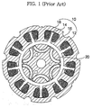
- the conventional stator may have the yoke and teeth integrated with each other by the iron powder metallurgy method.
- a stator 40 may be manufactured such that a yoke 42 is cut out from an electrical steel sheet and teeth 44 are manufactured by the iron powder metallurgy method.
- stator manufactured by the conventional process if all conditions except for the stator 10 in Figs. 1 and 2 and the manufacturing method are same, manufacturing costs can be reduced by manufacturing some parts using the iron powder metallurgy method in comparison to the stator 10 in Figs. 1 and 2.
- the efficiency of a motor including the conventional stator in Fig. 3 becomes remarkably worse than that of a motor including the stator 10 in Figs. 1 and 2.
- the present invention has been made in view of the above and/or other problems, and it is an object of the present invention to provide a stator of a motor of which some parts of the stator are manufactured according to the iron powder metallurgy method so as to reduce costs, to minimize core loss, and to enhance the efficiency of a motor due to the overhang effect.
- a stator of a motor including a plurality of teeth spaced apart from each other along the circumference of a rotor, a yoke for connecting the teeth to each other, and coils wound around the teeth, wherein the height of a tip of each tooth facing the rotor is lower than the height of the rotor, and the height of the yoke is higher than the height of the tip of each tooth.
- the teeth and the yoke are integrated with each other by the iron powder metallurgy method.
- each tooth is equal to or greater than the height of the tip of each tooth, but not higher than the height of the yoke.
- the teeth are manufactured by the iron powder metallurgy method, and the yoke is manufactured from an electrical steel sheet by the spiral method.
- the height of the connector of each tooth is equal to or greater than the height of the tip of each tooth, but not higher than the height of the yoke.
- the teeth are manufactured by the iron metallurgy method so as to minimize the manufacturing costs.
- the height of the tip of each tooth is lower than the height of the rotor and the height of the yoke is higher than the height of the tip of each tooth, so that the proper efficiency of a motor can be obtained.
- stator Since the basic structure of the stator is identical to that of a stator of a conventional motor, a detailed description thereof will be omitted.
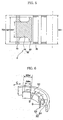
- Figs. 4 to 7 are views illustrating the stator of a motor according to the preferred embodiment of the present invention.
- the stator S of a motor includes a plurality of teeth 60 spaced apart from each other in the circumferential direction (indicated by an arrow C) by slots 52 formed therebetween, a ring-shaped yoke 70 for integrating the teeth 60 in one body, and coils (not shown) wound around the teeth 60.
- At least the tip 62 among the components constituting the teeth 60 is manufactured to have a height 62H lower than the height 50H of the rotor 50.
- a height 70H of the yoke 70 is higher than the height 62H of the tip 62 of the tooth 60 so that the core loss can be minimized even when the height 62H of the tip 62 of the tooth 60 is lower than the height 50H of the rotor 50.
- a motor has following advantages.
- the sectional area of the yoke 70 is increased as the height 70H of the yoke 70 is higher than the height 62H of the tip 62 of the tooth 60, the core loss of the yoke 70 is minimized.
- manufacturing costs are also increased in proportion to the sectional area of the yoke 70.
- the sectional area and the outer diameter of the yoke 70 are limited, since the inner diameter of the yoke 70 becomes relatively large as the height 70H of the yoke 70 is higher than the height 62H of the tip 62 of the tooth 60 so that the slots 52 can be formed to have greater widths, windings of the coils can be advantageously designed. In addition, since the circumferential widths of the teeth 60 can be relatively widened, the sectional areas of the teeth 60 can be increased and the core loss of the teeth 60 can be decreased.
- the teeth 60 and the yoke 70 constructed as described above are preferably integrated with each other by the iron powder metallurgy method so as to obtain the overhang effect and the minimization of the core loss of the yoke 70 simultaneously and to minimize the manufacturing costs.
- Fig. 6 is a partially cut perspective view illustrating a stator of a motor according to the present invention
- Fig. 7 is a cross-sectional view taken along the line B-B in Fig. 6.
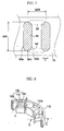
- stator according to the present invention may be manufactured such that the heights 64H of the necks 64 of the teeth 60 gradually increase from the sides 64a and 64b to the central portion 64c in the circumferential direction (arrow C).
- the necks 64 of the teeth 69 may have an oval cross-section.
- the necks 64 of the teeth are gradually spaced apart from neighboring necks 64, in other words, the distance between ends of neighboring necks 64 is gradually increased and the slots 52 are also gradually increased while the upper and lower sides of the necks 64 towards the upper ends of the necks 64, the end coil, which is protruded from each neck 64 of the teeth 60, can be minimized.
- the copper loss is decreased when the end coil is reduced so that the electric resistance is reduced, thus, the efficiency of the motor can be enhanced.
- the widths 64W of the necks 64 of the teeth 60 can be widened when the outer diameter and the sectional area of the yoke 70 are uniform, the height 64H may be lower than those of the tips 62 of the teeth 60 and the widths 64W may be narrower than the widths 62W of the tips 62 of the teeth 60.
- the teeth 60 and the yoke 70 are integrally manufactured by the iron powder metallurgy method so that they can be designed to have various shapes in comparison with when they are manufactured from the electrical steel sheet as shown in Figs. 1 and 2, and the manufacturing costs can also be reduced.
- the heights 62H of the tips 62 of the teeth 60 are lower than the height 50H of the rotor 50 and the height 70H of the yoke 70 is higher than the heights 62H of the tips 62 of the teeth 60, the efficiency of the motor cannot be deteriorated in comparison with the motor employing the stator manufactured from the electrical steel sheet as shown in Figs. 1 and 2.
- the efficiency of the motor is more enhanced.
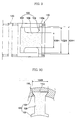
- the stator depicted in Figs. 8 through 10 is manufactured such that teeth 100 are manufactured by the iron powder metallurgy method and a yoke 110 is manufactured from an electrical steel sheet by the spiral method, and then they are coupled with each other.
- Each tooth 100 faces a rotor 120 in the radial direction, and includes a tip 102 having a lower height 102H than those of the rotor 120 and a yoke 110, a connector 104 coupled with the yoke 110, and a neck 106, disposed between the connector 104 and the tip 102, around which a coil is wound.
- the connector 104 is inserted into a connecting recess 110a formed on the inner wall of the yoke 110 so as to fit the teeth 100 into the yoke 110 in the vertical direction.
- the width 104W of the connector 104 of each tooth 100 may be gradually widened while running toward the yoke 100, and the planar sectional shapes of the teeth 100, the connector 104, and a connector recess 110a of the yoke 110 may have a trapezoidal shape so as to form the planar sectional shape of the connector recess 110a of the yoke 110 identical to that of the connector 104.
- the teeth 100, the connector 104, and the connector recess 110a of the yoke 110 may have a trapezoidal shape.
- At least the height 104H of the connector 104 of each tooth 100 is the same as the height 102H of the tip 102 of each tooth 100, but not higher than that of the yoke 110.
- the height 106H of the neck 106 of each tooth 100 may be lower than the height 102H of the tip 102 of each tooth 100, or may be gradually higher while running from the sides of the neck 106 to the central portion of the neck 106 in the circumferential direction.
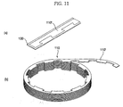
- the yoke 110 as shown in Fig. 11, is manufactured such that, at first, a strap-like yoke 110', which has a shape that a ring-shaped yoke 110 is straightened, is cut away from an electrical steel sheet 130 (See Fig. 11a), and the strap-like yoke 110' is wound to a desired height to form a spiral shape (See Fig. 11b).
- the manufacturing costs can be reduced and sufficient efficiency of a motor can be obtained in comparison with a motor having the stator in Figs. 1 and 2 manufactured from the electrical steel sheet.
Landscapes
- Engineering & Computer Science (AREA)
- Power Engineering (AREA)
- Iron Core Of Rotating Electric Machines (AREA)
- Manufacture Of Motors, Generators (AREA)
Applications Claiming Priority (1)
| Application Number | Priority Date | Filing Date | Title |
|---|---|---|---|
| KR1020040067202A KR100673442B1 (ko) | 2004-08-25 | 2004-08-25 | 모터의 스테이터 |
Publications (3)
| Publication Number | Publication Date |
|---|---|
| EP1630929A2 true EP1630929A2 (de) | 2006-03-01 |
| EP1630929A3 EP1630929A3 (de) | 2006-05-10 |
| EP1630929B1 EP1630929B1 (de) | 2012-10-03 |
Family
ID=36093611
Family Applications (1)
| Application Number | Title | Priority Date | Filing Date |
|---|---|---|---|
| EP05016776A Ceased EP1630929B1 (de) | 2004-08-25 | 2005-08-02 | Motorstators |
Country Status (7)
| Country | Link |
|---|---|
| US (1) | US7372184B2 (de) |
| EP (1) | EP1630929B1 (de) |
| JP (1) | JP2006067789A (de) |
| KR (1) | KR100673442B1 (de) |
| CN (1) | CN100399675C (de) |
| AU (1) | AU2005203421B2 (de) |
| RU (1) | RU2330370C2 (de) |
Cited By (1)
| Publication number | Priority date | Publication date | Assignee | Title |
|---|---|---|---|---|
| CN106936229A (zh) * | 2015-12-29 | 2017-07-07 | 珠海格力节能环保制冷技术研究中心有限公司 | 压缩机、电机及其定子机构 |
Families Citing this family (28)
| Publication number | Priority date | Publication date | Assignee | Title |
|---|---|---|---|---|
| US20090026876A1 (en) * | 2003-12-18 | 2009-01-29 | Intelligent Electric Motor Solutions Pty Ltd | Hybrid construction electric machine |
| MY148155A (en) * | 2005-10-24 | 2013-03-15 | Panasonic Corp | Capacitor motor and process for producing the same |
| KR101143994B1 (ko) * | 2006-03-09 | 2012-05-09 | 주식회사 동서전자 | 모터의 스테이터 |
| KR101143993B1 (ko) * | 2006-03-09 | 2012-05-09 | 주식회사 동서전자 | 모터의 스테이터 |
| DE102006023999A1 (de) * | 2006-05-22 | 2008-01-17 | Siemens Ag | Elektrische Maschine |
| JP4630858B2 (ja) * | 2006-10-30 | 2011-02-09 | 株式会社三井ハイテック | 積層鉄心およびその製造方法 |
| KR100845854B1 (ko) * | 2006-12-06 | 2008-07-14 | 엘지전자 주식회사 | 모터 |
| KR100883592B1 (ko) * | 2006-12-06 | 2009-02-13 | 엘지전자 주식회사 | 모터 |
| WO2008069360A2 (en) | 2006-12-06 | 2008-06-12 | Lg Electronics Inc. | Motor |
| ES2399137T3 (es) * | 2007-06-18 | 2013-03-26 | Askoll Holding S.R.L. | Motor eléctrico sincrónico bifásico |
| US8043221B2 (en) * | 2007-08-17 | 2011-10-25 | General Electric Company | Multi-headed imaging probe and imaging system using same |
| US8040007B2 (en) * | 2008-07-28 | 2011-10-18 | Direct Drive Systems, Inc. | Rotor for electric machine having a sleeve with segmented layers |
| WO2010030907A1 (en) * | 2008-09-12 | 2010-03-18 | Milwaukee Electric Tool Corporation | Field stack for a motor |
| CN102596672B (zh) | 2009-09-15 | 2015-03-04 | Kpit技术有限责任公司 | 根据预测的驱动变化向一种混合动力交通工具提供的引擎辅助 |
| CN102792009A (zh) * | 2009-09-15 | 2012-11-21 | Kpit康明斯信息系统有限责任公司 | 采用引擎作为原动力的交通工具的混合动力驱动系统 |
| US8423214B2 (en) | 2009-09-15 | 2013-04-16 | Kpit Cummins Infosystems, Ltd. | Motor assistance for a hybrid vehicle |
| JP5926182B2 (ja) * | 2009-09-15 | 2016-05-25 | ケーピーアイティ テクノロジーズ リミテッド | ユーザ入力に基づくハイブリッド車のモータ補助 |
| MX2012003114A (es) | 2009-09-15 | 2012-06-19 | Kpit Cummins Infosystems Ltd | Metodo para convertir un vehiculo en un vehiculo hibrido. |
| WO2011039769A2 (en) * | 2009-09-15 | 2011-04-07 | Kpit Cummins Infosystems Ltd. | Hybrid drive system with reduced power requirement for vehicle |
| CN102244419A (zh) * | 2011-07-13 | 2011-11-16 | 东莞市毅瑞得电机有限公司 | 一种方便绕线的电机定子及其生产方法 |
| CN102437661A (zh) * | 2011-12-23 | 2012-05-02 | 宁波韵升股份有限公司 | 车辆用交流发电机的定子铁芯 |
| US8941274B2 (en) | 2012-03-23 | 2015-01-27 | Whirlpool Corporation | Stator for an electric motor of a washing machine and method of manufacturing the same |
| JP2014023359A (ja) * | 2012-07-20 | 2014-02-03 | Nippon Piston Ring Co Ltd | 回転電機 |
| CN103834855B (zh) * | 2012-11-27 | 2016-05-11 | 安徽省恒宇粉末冶金有限公司 | 粉末冶金制动器磁轭配方及制作工艺 |
| KR102040147B1 (ko) | 2013-06-20 | 2019-11-04 | 삼성전자주식회사 | 전기 모터의 회전자 및 이를 채용한 모터 |
| EP3304694A2 (de) * | 2015-05-29 | 2018-04-11 | Francecol Technology | Elektromagnetische armatur für eine rotierende elektrische maschine und verfahren zur herstellung davon |
| CN107919744A (zh) * | 2016-10-08 | 2018-04-17 | 珠海凌达压缩机有限公司 | 一种定子铁芯结构和一种电机 |
| CN108539946B (zh) * | 2017-03-03 | 2024-06-14 | 山东中瑞电子股份有限公司 | 一种分数槽集中绕组永磁无刷电机的定子的制造方法 |
Citations (4)
| Publication number | Priority date | Publication date | Assignee | Title |
|---|---|---|---|---|
| US5798583A (en) | 1995-07-26 | 1998-08-25 | Kabushiki Kaisha Toshiba | Spindle motor having recessed stator coils |
| US5853513A (en) | 1995-02-22 | 1998-12-29 | Mobile Storage Technology Inc. | Method of producing a stator for a disk drive motor |
| JP2000324777A (ja) | 1999-04-30 | 2000-11-24 | Victor Co Of Japan Ltd | ディスク駆動装置 |
| US20030168926A1 (en) | 2002-03-08 | 2003-09-11 | Zepp Lawrence P. | Electrical machine construction using axially inserted teeth in a stator ring or armature |
Family Cites Families (51)
| Publication number | Priority date | Publication date | Assignee | Title |
|---|---|---|---|---|
| SU486428A1 (ru) | 1972-08-23 | 1975-09-30 | Всесоюзный Научно-Исследовательский Проектно-Конструкторский Институт Технологии Электротехнических Машин Малой Мощности | Способ изготовлени и сборки статоров электрических машин |
| SU729754A1 (ru) | 1978-11-10 | 1980-04-25 | Предприятие П/Я А-3084 | Магнитопровод статора торцевой электрической машины |
| SU936226A2 (ru) | 1980-07-10 | 1982-06-15 | Всесоюзный Научно-Исследовательский Проектно-Конструкторский Институт Технологии Электрических Машин Малой Мощности | Статор торцовой электрической машины |
| SU1001316A1 (ru) | 1981-06-29 | 1983-02-28 | Всесоюзный Заочный Инженерно-Строительный Институт | Магнитопровод торцовой электрической машины |
| SU1234915A1 (ru) | 1984-02-29 | 1986-05-30 | Всесоюзный научно-исследовательский проектно-конструкторский и технологический институт электромашиностроения | Магнитопровод электрической машины |
| DE3436511A1 (de) | 1984-10-05 | 1986-04-10 | Robert Bosch Gmbh, 7000 Stuttgart | Elektromaschine, insbesondere als antrieb fuer eine umwaelzpumpe |
| SU1343500A1 (ru) * | 1985-05-20 | 1987-10-07 | Всесоюзный научно-исследовательский проектно-конструкторский и технологический институт электромашиностроения | Магнитопровод электрической машины |
| US4835839A (en) * | 1985-11-12 | 1989-06-06 | General Electric Company | Method of fabricating a salient pole electronically commutated motor |
| SU1374337A1 (ru) * | 1986-07-14 | 1988-02-15 | Харьковский авиационный институт им.Н.Е.Жуковского | Статор электрической машины |
| SU1379872A1 (ru) * | 1986-08-04 | 1988-03-07 | Харьковский авиационный институт им.Н.Е.Жуковского | Статор электрической машины |
| JPH0191628A (ja) * | 1987-10-02 | 1989-04-11 | Matsushita Electric Ind Co Ltd | 固定子 |
| JPH04372557A (ja) * | 1991-06-24 | 1992-12-25 | Shibaura Eng Works Co Ltd | 電動機 |
| US5489811A (en) * | 1992-06-11 | 1996-02-06 | Generac Corporation | Permanent magnet alternator |
| JPH09261925A (ja) * | 1996-03-21 | 1997-10-03 | Toshiba Corp | インナーロータ型回転電機のステータ製造方法 |
| JP3359863B2 (ja) | 1998-04-08 | 2002-12-24 | 三菱電機株式会社 | 固定子鉄芯の製造方法 |
| JP2000184628A (ja) | 1998-12-10 | 2000-06-30 | Sanyo Electric Co Ltd | モータのステータ |
| JP2000236638A (ja) * | 1999-02-16 | 2000-08-29 | Hitachi Ltd | 回転電機の固定子 |
| JP3563650B2 (ja) * | 1999-10-25 | 2004-09-08 | 株式会社日立産機システム | 回転電機 |
| JP4665275B2 (ja) * | 1999-11-22 | 2011-04-06 | シンフォニアテクノロジー株式会社 | 高耐熱回転電機 |
| FR2804552B1 (fr) * | 2000-01-28 | 2003-01-03 | Leroy Somer | Procede de fabrication d'un circuit de machine electrique |
| JP2001238420A (ja) | 2000-02-22 | 2001-08-31 | Mitsubishi Electric Corp | 同期電動機 |
| US6580193B2 (en) * | 2000-03-31 | 2003-06-17 | Asmo Co., Ltd. | Rotary electric machine and manufacturing method therefor |
| DE10026009A1 (de) * | 2000-05-25 | 2001-12-06 | Bosch Gmbh Robert | Vorrichtung mit einem Stator und einer Hülse |
| JP2002101583A (ja) * | 2000-09-20 | 2002-04-05 | Fujitsu General Ltd | 電動機 |
| JP2002136003A (ja) * | 2000-10-24 | 2002-05-10 | Mitsubishi Electric Corp | 回転電機の固定子 |
| JP2002176753A (ja) * | 2000-12-07 | 2002-06-21 | Matsushita Electric Ind Co Ltd | 電動機固定子の製造方法及びその固定子 |
| JP2002176738A (ja) * | 2000-12-08 | 2002-06-21 | Sofutoronikusu Kk | サーボモータおよびサーボモータの製造方法 |
| JP3593038B2 (ja) | 2001-01-16 | 2004-11-24 | 三菱電機株式会社 | 車両用交流発電機 |
| RU2210161C2 (ru) * | 2001-03-05 | 2003-08-10 | Общество с ограниченной ответственностью Опытно-промышленная фирма "ЭЛТРОН" | Электрическая машина |
| JP2002272073A (ja) * | 2001-03-08 | 2002-09-20 | Nissan Motor Co Ltd | 回転電機 |
| JP2002369418A (ja) * | 2001-06-04 | 2002-12-20 | Nissan Motor Co Ltd | 電動機のステータ構造 |
| JP3753034B2 (ja) * | 2001-08-28 | 2006-03-08 | 日産自動車株式会社 | モータの回転子構造および回転子固定方法ならびに鉄心保持具 |
| TW577658U (en) * | 2001-09-10 | 2004-02-21 | Adlee Powertronic Co Ltd | Rotor structure for a motor having built-in type permanebt magnet |
| JP2003169431A (ja) * | 2001-11-29 | 2003-06-13 | Hitachi Ltd | 電動機 |
| JP2003224940A (ja) * | 2002-01-29 | 2003-08-08 | Asmo Co Ltd | 回転電機のステータ |
| US6566784B1 (en) * | 2002-05-16 | 2003-05-20 | Chun-Pu Hsu | Stator structure with single-arm tooth holders |
| JP2004040948A (ja) | 2002-07-05 | 2004-02-05 | Toyoda Mach Works Ltd | モータ |
| CN1317809C (zh) * | 2002-08-20 | 2007-05-23 | 多摩川精机株式会社 | 定子线圈的卷绕方法和结构 |
| KR100484817B1 (ko) * | 2002-10-10 | 2005-04-22 | 엘지전자 주식회사 | 세탁기용 모터의 코어 제조방법 |
| JP3987413B2 (ja) * | 2002-10-22 | 2007-10-10 | ミネベア株式会社 | モータ |
| DE10251647B4 (de) | 2002-10-30 | 2016-09-15 | Xylem Ip Holdings Llc | Elektromotor |
| US7111380B2 (en) * | 2002-10-31 | 2006-09-26 | Emerson Electric Co. | Method for forming an annular stator assembly |
| DE10252316A1 (de) * | 2002-11-11 | 2004-06-09 | Minebea Co., Ltd. | Statorkörper für einen Innenläufer-Gleichstrommotor |
| JP4240456B2 (ja) * | 2002-12-13 | 2009-03-18 | 株式会社ミツバ | ブラシレスモータ |
| JP3791492B2 (ja) * | 2002-12-25 | 2006-06-28 | 株式会社日立製作所 | 回転電機及び電動車両並びに樹脂のインサート成形方法 |
| JP3733120B2 (ja) * | 2002-12-27 | 2006-01-11 | 穩正企業股▲ふん▼有限公司 | モータの組合せ式固定子構造 |
| JP4430310B2 (ja) * | 2003-01-07 | 2010-03-10 | 本田技研工業株式会社 | ステータの製造方法および製造装置 |
| US6844653B2 (en) * | 2003-03-31 | 2005-01-18 | Valeo Electrical Systems, Inc. | Stator design for permanent magnet motor with combination slot wedge and tooth locator |
| US20060226729A1 (en) * | 2003-09-05 | 2006-10-12 | Du Hung T | Field assemblies and methods of making same with field coils having multiple coils |
| JP4586717B2 (ja) * | 2004-12-10 | 2010-11-24 | 日本電産株式会社 | モータ |
| JP2006246621A (ja) * | 2005-03-03 | 2006-09-14 | Asmo Co Ltd | 回転電機のコア、その製造方法、及び埋込磁石型モータ |
-
2004
- 2004-08-25 KR KR1020040067202A patent/KR100673442B1/ko not_active Expired - Lifetime
-
2005
- 2005-08-02 AU AU2005203421A patent/AU2005203421B2/en not_active Ceased
- 2005-08-02 EP EP05016776A patent/EP1630929B1/de not_active Ceased
- 2005-08-15 US US11/203,248 patent/US7372184B2/en not_active Expired - Lifetime
- 2005-08-24 JP JP2005242254A patent/JP2006067789A/ja active Pending
- 2005-08-24 RU RU2005126790/09A patent/RU2330370C2/ru active
- 2005-08-25 CN CNB2005100965636A patent/CN100399675C/zh not_active Expired - Fee Related
Patent Citations (4)
| Publication number | Priority date | Publication date | Assignee | Title |
|---|---|---|---|---|
| US5853513A (en) | 1995-02-22 | 1998-12-29 | Mobile Storage Technology Inc. | Method of producing a stator for a disk drive motor |
| US5798583A (en) | 1995-07-26 | 1998-08-25 | Kabushiki Kaisha Toshiba | Spindle motor having recessed stator coils |
| JP2000324777A (ja) | 1999-04-30 | 2000-11-24 | Victor Co Of Japan Ltd | ディスク駆動装置 |
| US20030168926A1 (en) | 2002-03-08 | 2003-09-11 | Zepp Lawrence P. | Electrical machine construction using axially inserted teeth in a stator ring or armature |
Cited By (1)
| Publication number | Priority date | Publication date | Assignee | Title |
|---|---|---|---|---|
| CN106936229A (zh) * | 2015-12-29 | 2017-07-07 | 珠海格力节能环保制冷技术研究中心有限公司 | 压缩机、电机及其定子机构 |
Also Published As
| Publication number | Publication date |
|---|---|
| US7372184B2 (en) | 2008-05-13 |
| KR20060018704A (ko) | 2006-03-02 |
| RU2005126790A (ru) | 2007-02-27 |
| CN100399675C (zh) | 2008-07-02 |
| AU2005203421B2 (en) | 2007-12-20 |
| AU2005203421A1 (en) | 2006-03-16 |
| KR100673442B1 (ko) | 2007-01-24 |
| RU2330370C2 (ru) | 2008-07-27 |
| JP2006067789A (ja) | 2006-03-09 |
| EP1630929B1 (de) | 2012-10-03 |
| CN1741347A (zh) | 2006-03-01 |
| EP1630929A3 (de) | 2006-05-10 |
| US20060055275A1 (en) | 2006-03-16 |
Similar Documents
| Publication | Publication Date | Title |
|---|---|---|
| EP1630929A2 (de) | Motorstators | |
| JP2012023861A (ja) | 電機子鉄心とモータ | |
| EP1095442B1 (de) | Stator mit zähnen aus weichmagnetischem pulverförmigem material. | |
| EP3211772B1 (de) | Statorherstellungsverfahren und spule | |
| JP6843271B2 (ja) | 電動機及び空気調和機 | |
| US7227291B2 (en) | Stator for an electrical machine | |
| US7511401B2 (en) | Rotor of motor | |
| EP1341288B1 (de) | Drehenden elektrischen Maschine | |
| JP2025172906A (ja) | ロータ及びモータ | |
| CN111602323A (zh) | 绝缘体、包括该绝缘体的定子以及包括该绝缘体的电动机 | |
| EP1701427A1 (de) | Stator für einen Motor | |
| US10720799B2 (en) | Stator of rotary electric machine | |
| US20060186748A1 (en) | Motor case | |
| JP2022110252A (ja) | 電機子の製造方法、電機子、及び鉄心 | |
| JP5109737B2 (ja) | 分割ステータコアの製造方法 | |
| CN212462909U (zh) | 转子和具备该转子的马达 | |
| JP2018074698A (ja) | 回転電機の固定子および固定子巻線の製造方法 | |
| CN219145115U (zh) | 磁悬浮泵的定子组件、磁悬浮泵及透平装置 | |
| JP2014014215A (ja) | 回転電機の固定子 | |
| CN221227239U (zh) | 定子组件和具有其的电机 | |
| CN220172934U (zh) | 一种定子冲片及定子 | |
| CN112886739B (zh) | 转子铁芯、电机转子、电机 | |
| US20260081489A1 (en) | Electric machine with rotor magnet tabs | |
| EP2725590B1 (de) | Spulendrahtträgerelement, Herstellungsverfahren dafür und induktiver Energieübertragungskoppler damit | |
| JP2011072058A (ja) | 回転電機 |
Legal Events
| Date | Code | Title | Description |
|---|---|---|---|
| PUAI | Public reference made under article 153(3) epc to a published international application that has entered the european phase |
Free format text: ORIGINAL CODE: 0009012 |
|
| 17P | Request for examination filed |
Effective date: 20050802 |
|
| AK | Designated contracting states |
Kind code of ref document: A2 Designated state(s): AT BE BG CH CY CZ DE DK EE ES FI FR GB GR HU IE IS IT LI LT LU LV MC NL PL PT RO SE SI SK TR |
|
| AX | Request for extension of the european patent |
Extension state: AL BA HR MK YU |
|
| PUAL | Search report despatched |
Free format text: ORIGINAL CODE: 0009013 |
|
| AK | Designated contracting states |
Kind code of ref document: A3 Designated state(s): AT BE BG CH CY CZ DE DK EE ES FI FR GB GR HU IE IS IT LI LT LU LV MC NL PL PT RO SE SI SK TR |
|
| AX | Request for extension of the european patent |
Extension state: AL BA HR MK YU |
|
| AKX | Designation fees paid |
Designated state(s): DE FR GB |
|
| 17Q | First examination report despatched |
Effective date: 20070209 |
|
| RIC1 | Information provided on ipc code assigned before grant |
Ipc: H02K 1/14 20060101ALI20111222BHEP Ipc: H02K 21/16 20060101AFI20111222BHEP |
|
| REG | Reference to a national code |
Ref country code: DE Ref legal event code: R079 Ref document number: 602005036349 Country of ref document: DE Free format text: PREVIOUS MAIN CLASS: H02K0001140000 Ipc: H02K0041035000 |
|
| GRAP | Despatch of communication of intention to grant a patent |
Free format text: ORIGINAL CODE: EPIDOSNIGR1 |
|
| RIC1 | Information provided on ipc code assigned before grant |
Ipc: H02K 41/035 20060101AFI20120306BHEP |
|
| RAP1 | Party data changed (applicant data changed or rights of an application transferred) |
Owner name: LG ELECTRONICS INC. |
|
| GRAS | Grant fee paid |
Free format text: ORIGINAL CODE: EPIDOSNIGR3 |
|
| GRAA | (expected) grant |
Free format text: ORIGINAL CODE: 0009210 |
|
| AK | Designated contracting states |
Kind code of ref document: B1 Designated state(s): DE FR GB |
|
| REG | Reference to a national code |
Ref country code: GB Ref legal event code: FG4D |
|
| REG | Reference to a national code |
Ref country code: DE Ref legal event code: R096 Ref document number: 602005036349 Country of ref document: DE Effective date: 20121129 |
|
| PLBE | No opposition filed within time limit |
Free format text: ORIGINAL CODE: 0009261 |
|
| STAA | Information on the status of an ep patent application or granted ep patent |
Free format text: STATUS: NO OPPOSITION FILED WITHIN TIME LIMIT |
|
| 26N | No opposition filed |
Effective date: 20130704 |
|
| REG | Reference to a national code |
Ref country code: DE Ref legal event code: R097 Ref document number: 602005036349 Country of ref document: DE Effective date: 20130704 |
|
| REG | Reference to a national code |
Ref country code: FR Ref legal event code: PLFP Year of fee payment: 12 |
|
| REG | Reference to a national code |
Ref country code: FR Ref legal event code: PLFP Year of fee payment: 13 |
|
| PGFP | Annual fee paid to national office [announced via postgrant information from national office to epo] |
Ref country code: IT Payment date: 20170726 Year of fee payment: 13 |
|
| REG | Reference to a national code |
Ref country code: FR Ref legal event code: PLFP Year of fee payment: 14 |
|
| GBPC | Gb: european patent ceased through non-payment of renewal fee |
Effective date: 20180802 |
|
| PG25 | Lapsed in a contracting state [announced via postgrant information from national office to epo] |
Ref country code: GB Free format text: LAPSE BECAUSE OF NON-PAYMENT OF DUE FEES Effective date: 20180802 |
|
| PGFP | Annual fee paid to national office [announced via postgrant information from national office to epo] |
Ref country code: FR Payment date: 20200709 Year of fee payment: 16 |
|
| PG25 | Lapsed in a contracting state [announced via postgrant information from national office to epo] |
Ref country code: FR Free format text: LAPSE BECAUSE OF NON-PAYMENT OF DUE FEES Effective date: 20210831 |
|
| PGFP | Annual fee paid to national office [announced via postgrant information from national office to epo] |
Ref country code: DE Payment date: 20220615 Year of fee payment: 18 |
|
| REG | Reference to a national code |
Ref country code: DE Ref legal event code: R119 Ref document number: 602005036349 Country of ref document: DE |
|
| PG25 | Lapsed in a contracting state [announced via postgrant information from national office to epo] |
Ref country code: DE Free format text: LAPSE BECAUSE OF NON-PAYMENT OF DUE FEES Effective date: 20240301 |