EP1632115B1 - Tragbares elektronisches gerät mit flexibler verbindung zwischen interner elektronik und einer hilfsverbindung - Google Patents
Tragbares elektronisches gerät mit flexibler verbindung zwischen interner elektronik und einer hilfsverbindung Download PDFInfo
- Publication number
- EP1632115B1 EP1632115B1 EP04702014A EP04702014A EP1632115B1 EP 1632115 B1 EP1632115 B1 EP 1632115B1 EP 04702014 A EP04702014 A EP 04702014A EP 04702014 A EP04702014 A EP 04702014A EP 1632115 B1 EP1632115 B1 EP 1632115B1
- Authority
- EP
- European Patent Office
- Prior art keywords
- connector
- auxiliary
- housing
- insertion force
- low insertion
- Prior art date
- Legal status (The legal status is an assumption and is not a legal conclusion. Google has not performed a legal analysis and makes no representation as to the accuracy of the status listed.)
- Expired - Lifetime
Links
- 238000003780 insertion Methods 0.000 claims description 59
- 230000037431 insertion Effects 0.000 claims description 59
- 229920001971 elastomer Polymers 0.000 claims description 25
- 239000000806 elastomer Substances 0.000 claims description 25
- 230000007246 mechanism Effects 0.000 claims description 12
- 239000002184 metal Substances 0.000 claims description 7
- 229910052751 metal Inorganic materials 0.000 claims description 7
- 239000000853 adhesive Substances 0.000 claims description 6
- 230000001070 adhesive effect Effects 0.000 claims description 6
- 238000004891 communication Methods 0.000 claims description 6
- 239000000463 material Substances 0.000 claims description 5
- 230000037361 pathway Effects 0.000 claims description 4
- 238000000034 method Methods 0.000 claims description 3
- 239000002245 particle Substances 0.000 claims description 3
- 239000004020 conductor Substances 0.000 claims description 2
- PCHJSUWPFVWCPO-UHFFFAOYSA-N gold Chemical compound [Au] PCHJSUWPFVWCPO-UHFFFAOYSA-N 0.000 claims description 2
- 229910052737 gold Inorganic materials 0.000 claims description 2
- 239000010931 gold Substances 0.000 claims description 2
- 229910000679 solder Inorganic materials 0.000 description 8
- 230000013011 mating Effects 0.000 description 6
- 238000013461 design Methods 0.000 description 5
- 238000012986 modification Methods 0.000 description 3
- 230000004048 modification Effects 0.000 description 3
- 230000008878 coupling Effects 0.000 description 2
- 238000010168 coupling process Methods 0.000 description 2
- 238000005859 coupling reaction Methods 0.000 description 2
- 238000010295 mobile communication Methods 0.000 description 2
- 229920002379 silicone rubber Polymers 0.000 description 2
- BQCADISMDOOEFD-UHFFFAOYSA-N Silver Chemical compound [Ag] BQCADISMDOOEFD-UHFFFAOYSA-N 0.000 description 1
- 229910052770 Uranium Inorganic materials 0.000 description 1
- 239000002313 adhesive film Substances 0.000 description 1
- 230000000712 assembly Effects 0.000 description 1
- 238000000429 assembly Methods 0.000 description 1
- 230000015572 biosynthetic process Effects 0.000 description 1
- 238000011109 contamination Methods 0.000 description 1
- 239000000428 dust Substances 0.000 description 1
- 239000013536 elastomeric material Substances 0.000 description 1
- 229920000642 polymer Polymers 0.000 description 1
- 230000035939 shock Effects 0.000 description 1
- 239000004945 silicone rubber Substances 0.000 description 1
- 229910052709 silver Inorganic materials 0.000 description 1
- 239000004332 silver Substances 0.000 description 1
Images





Classifications
-
- H—ELECTRICITY
- H01—ELECTRIC ELEMENTS
- H01R—ELECTRICALLY-CONDUCTIVE CONNECTIONS; STRUCTURAL ASSOCIATIONS OF A PLURALITY OF MUTUALLY-INSULATED ELECTRICAL CONNECTING ELEMENTS; COUPLING DEVICES; CURRENT COLLECTORS
- H01R13/00—Details of coupling devices of the kinds covered by groups H01R12/70 or H01R24/00 - H01R33/00
- H01R13/02—Contact members
- H01R13/22—Contacts for co-operating by abutting
- H01R13/24—Contacts for co-operating by abutting resilient; resiliently-mounted
- H01R13/2407—Contacts for co-operating by abutting resilient; resiliently-mounted characterized by the resilient means
- H01R13/2414—Contacts for co-operating by abutting resilient; resiliently-mounted characterized by the resilient means conductive elastomers
-
- H—ELECTRICITY
- H01—ELECTRIC ELEMENTS
- H01R—ELECTRICALLY-CONDUCTIVE CONNECTIONS; STRUCTURAL ASSOCIATIONS OF A PLURALITY OF MUTUALLY-INSULATED ELECTRICAL CONNECTING ELEMENTS; COUPLING DEVICES; CURRENT COLLECTORS
- H01R12/00—Structural associations of a plurality of mutually-insulated electrical connecting elements, specially adapted for printed circuits, e.g. printed circuit boards [PCB], flat or ribbon cables, or like generally planar structures, e.g. terminal strips, terminal blocks; Coupling devices specially adapted for printed circuits, flat or ribbon cables, or like generally planar structures; Terminals specially adapted for contact with, or insertion into, printed circuits, flat or ribbon cables, or like generally planar structures
- H01R12/50—Fixed connections
- H01R12/59—Fixed connections for flexible printed circuits, flat or ribbon cables or like structures
- H01R12/592—Fixed connections for flexible printed circuits, flat or ribbon cables or like structures connections to contact elements
-
- H—ELECTRICITY
- H01—ELECTRIC ELEMENTS
- H01R—ELECTRICALLY-CONDUCTIVE CONNECTIONS; STRUCTURAL ASSOCIATIONS OF A PLURALITY OF MUTUALLY-INSULATED ELECTRICAL CONNECTING ELEMENTS; COUPLING DEVICES; CURRENT COLLECTORS
- H01R13/00—Details of coupling devices of the kinds covered by groups H01R12/70 or H01R24/00 - H01R33/00
- H01R13/02—Contact members
- H01R13/193—Means for increasing contact pressure at the end of engagement of coupling part, e.g. zero insertion force or no friction
-
- H—ELECTRICITY
- H01—ELECTRIC ELEMENTS
- H01R—ELECTRICALLY-CONDUCTIVE CONNECTIONS; STRUCTURAL ASSOCIATIONS OF A PLURALITY OF MUTUALLY-INSULATED ELECTRICAL CONNECTING ELEMENTS; COUPLING DEVICES; CURRENT COLLECTORS
- H01R12/00—Structural associations of a plurality of mutually-insulated electrical connecting elements, specially adapted for printed circuits, e.g. printed circuit boards [PCB], flat or ribbon cables, or like generally planar structures, e.g. terminal strips, terminal blocks; Coupling devices specially adapted for printed circuits, flat or ribbon cables, or like generally planar structures; Terminals specially adapted for contact with, or insertion into, printed circuits, flat or ribbon cables, or like generally planar structures
- H01R12/70—Coupling devices
- H01R12/77—Coupling devices for flexible printed circuits, flat or ribbon cables or like structures
-
- H—ELECTRICITY
- H01—ELECTRIC ELEMENTS
- H01R—ELECTRICALLY-CONDUCTIVE CONNECTIONS; STRUCTURAL ASSOCIATIONS OF A PLURALITY OF MUTUALLY-INSULATED ELECTRICAL CONNECTING ELEMENTS; COUPLING DEVICES; CURRENT COLLECTORS
- H01R12/00—Structural associations of a plurality of mutually-insulated electrical connecting elements, specially adapted for printed circuits, e.g. printed circuit boards [PCB], flat or ribbon cables, or like generally planar structures, e.g. terminal strips, terminal blocks; Coupling devices specially adapted for printed circuits, flat or ribbon cables, or like generally planar structures; Terminals specially adapted for contact with, or insertion into, printed circuits, flat or ribbon cables, or like generally planar structures
- H01R12/70—Coupling devices
- H01R12/82—Coupling devices connected with low or zero insertion force
-
- H—ELECTRICITY
- H01—ELECTRIC ELEMENTS
- H01R—ELECTRICALLY-CONDUCTIVE CONNECTIONS; STRUCTURAL ASSOCIATIONS OF A PLURALITY OF MUTUALLY-INSULATED ELECTRICAL CONNECTING ELEMENTS; COUPLING DEVICES; CURRENT COLLECTORS
- H01R2201/00—Connectors or connections adapted for particular applications
- H01R2201/16—Connectors or connections adapted for particular applications for telephony
-
- H—ELECTRICITY
- H04—ELECTRIC COMMUNICATION TECHNIQUE
- H04M—TELEPHONIC COMMUNICATION
- H04M1/00—Substation equipment, e.g. for use by subscribers
- H04M1/72—Mobile telephones; Cordless telephones, i.e. devices for establishing wireless links to base stations without route selection
- H04M1/724—User interfaces specially adapted for cordless or mobile telephones
- H04M1/72403—User interfaces specially adapted for cordless or mobile telephones with means for local support of applications that increase the functionality
- H04M1/72409—User interfaces specially adapted for cordless or mobile telephones with means for local support of applications that increase the functionality by interfacing with external accessories
Definitions
- the present invention relates to the field of portable electronic devices in general and more particularly, to electrical connectors to internal electrical circuits of such portable electronic devices, such as mobile communication devices.
- Portable electronic devices such as radiotelephones, personal data assistants (PDAs), smartphones, or other mobile devices may include auxiliary connectors electrically coupling the portable device to an external accessory device, such as MPEG Audio Layer 3 ("MP3") players, radios, cameras, headsets or other such devices.
- MP3 MPEG Audio Layer 3
- the auxiliary connector is typically accessible from the outside of the portable device. For example, a flat spring contact can be used to connect an accessory device to the auxiliary connector for communications with the portable electronic device.
- Auxiliary connectors are generally electrically connected to an electrical circuit, such as a printed circuit board, inside the housing of the portable device.
- This electrical connection is typically a solder or slide on design.
- solder or slide on connections are generally relatively tall, for example, 5mm in height or larger, and their size may place constraints on the placement of the printed circuit board within the housing of the portable device. The placement of the circuit board may, in turn, limit the ability of these designs to meet the design requirements of smaller portable devices.
- Anelectronic device comprising the features of the preambles of claims 1 and 24 is disclosed in DE 19802552A .
- Solder and slide on connection designs may also become unreliable due to exposure to shock conditions (e.g. , relatively high force impacts over a short time period) and/or normal wear and use (e.g. , relatively low force impacts over a longer time period).
- shock conditions e.g. , relatively high force impacts over a short time period
- normal wear and use e.g. , relatively low force impacts over a longer time period.
- solder joints bear some of the force that is impacted onto the auxiliary connector, and a solder joint configuration may not absorb the force of impact sufficiently to avoid damage. These impact forces can cause either fatigue of the solder joint and/or wear on the contact pads to the electrical circuit.
- a rugged mechanism may be required to hold the components together and such designs may lead to failure of the mechanical interfaces. The results of such conditions may be catastrophic.
- Embodiments of the present invention include a portable electronic device including a portable housing and an electrical circuit positioned in the housing.
- a connector assembly is positioned in a wall of the housing.
- the connector assembly includes an internal connector extending into the housing, and an auxiliary connector rigidly coupled to the internal connector and accessible from outside the housing.
- the auxiliary connector is electrically connected to the internal connector.
- a unitary body member rigidly couples the internal connector and the auxiliary connector.
- a flexible member electrically connects the internal connector to the electrical circuit. The flexible member is configured to transmit less than about 10% of an external impact force on the connector assembly to the electrical circuit.
- a wireless terminal including a portable housing and an electrical circuit positioned in the housing.
- the electrical circuit includes a wireless communications circuit on a printed circuit board including a processor and a processor system bus.
- a connector assembly having a height less than about 5mm is positioned in a wall of the housing.
- the connector assembly includes an internal connector extending into the housing and an auxiliary connector rigidly coupled to the internal connector and accessible from outside the housing.
- the auxiliary connector is electrically connected to the internal connector.
- the internal connector and the auxiliary connector each include a plurality of electrically isolated electrical contact points.
- the connector assembly includes a plurality of conductive members extending between respective ones of the electrical contact points and having a first end defining an electrical contact in the internal connector and a second end defining an associated electrical contact in the auxiliary connector.
- the plurality of conductive member comprises conductive pathways formed by conductive elastomer interconnects.
- a flexible member electrically connects the internal connector to the electrical circuit. The flexible member is configured to transmit less than about 10% of an external impact force on the connector assembly to the electrical circuit.
- a wireless terminal includes a portable housing and an electrical circuit positioned in the
- a method for connecting a connector assembly having a low insertion force connector to a flexible member in a portable electronic device includes a first housing portion and a second housing portion.
- a connector assembly is positioned in a wall of the first housing portion of the portable electronic device.
- the connector assembly includes a low insertion force connector comprising a first part and a second part. The second part is movable between a closed position and a open position.
- the connector assembly further includes an auxiliary connector rigidly coupled to the low insertion force connector and accessible from outside the housing.
- the auxiliary connector is electrically connected to the low insertion force connector.
- a flexible member is positioned between the first part and the second part of the low insertion force connector.
- the second housing portion of the portable electronic device is positioned on the first housing portion of the portable electronic device to move the second part of the low insertion force connector from the open position to the closed position retaining the flexible member in the low insertion force connector.
- the mobile terminal 10 includes a portable housing 12 having a top portion 20A and a bottom portion 20B.
- An electrical circuit 30 is positioned in the housing 12.
- the electrical circuit 30 can be a printed circuit board having a wireless communications circuit that can include a processor and a processor system bus.
- a connector assembly 40 is positioned in a wall 14 of the bottom housing portion 20B.
- the connector assembly 40 provides an interface between the electrical circuit 30 (e.g ., a processor system bus) and an auxiliary device 60 by way of a flexible connector 32.
- auxiliary or accessory devices include MPEG Audio Layer 3 ("MP3") players, radios, cameras, headsets and other devices that may be configured to interface with a mobile wireless terminal 10 or other portable electronic device.
- MP3 MPEG Audio Layer 3
- the connector assembly 40 has an auxiliary connector 54 that is accessible from outside of the housing 12 to provide a connection to the auxiliary device 60 and, through an internal connector 42 and flexible connector 32, a connection to the electrical circuit 30.
- the flexible connector 32 includes flexible conductive electrical leads (or traces) 34 that are electrically connected to the electrical circuit 30 via electrical contact termination points 36.
- Any suitable flexible connector can be used, such as a flexible printed circuit.
- the height of the electrical connection between the internal connector 42 and the electrical circuit 30 may be reduced relative to conventional solder joint connections.
- the height of the connector assembly 40 can be 5.5mm, 4mm, 3mm or less.
- the internal electrical connection may also have increased durability compared to conventional solder joint connections.
- the flexible connector 32 is compliant and can mechanically absorb and/or dissipate some of the energy from any impact to the exposed surface of the connector assembly 40. For example, if the mobile terminal 10 experiences a force of impact on the connector assembly 40, the flexible connector 32 may decouple a portion of the energy from the impact force to the electrical circuit 30. In certain embodiments, the flexible connector 32 transmits less than about 10% of an external impact force on the connector assembly 40 to the electrical circuit 30.
- the auxiliary connector 54 includes auxiliary contacts 50 and latches 52.
- the auxiliary contacts 50 are electrically coupled to the internal connector 42.
- the auxiliary device 60 includes a mating connector 62 that includes latches 64 and metal contacts 66.
- the latches 64 on the mating connector 62 mechanically connect with the latches 52 on the auxiliary connector 54 to help maintain an electrical connection between the metal contacts 66 and the auxiliary contacts 50. Accordingly, an electrical connection is formed between the auxiliary device 60 and the electrical circuit 30 of the mobile terminal 10.
- the internal connector 42 can be any connector configured to form an electrical connection with the flexible connector 32.
- suitable internal connectors include low insertion force connectors.
- Low insertion force connectors typically provide a force on a connector lead after insertion to maintain an electrical connection while also reducing the force on the lead during insertion.
- low insertion force connectors include connectors referred to as "zero" insertion force connectors.
- the internal connector 42 can be a snap-type connector or a connector using anisotropic conductive adhesive to electrically connect to the flexible connector 32.
- the auxiliary contacts 50 can be any suitable contact for forming a connection with the mating connector 62, such as a flat spring interface, a metal spring connector, or a compliant elastomer contact.
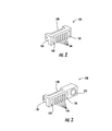
- FIGS 2 and 3 illustrate embodiments of the present invention showing the auxiliary connector side of connector assemblies 100 and 120, respectively.
- the connector assembly 100 includes six auxiliary contacts 104 and two latches 102 on the auxiliary connector side and an internal connector 108, which are incorporated in a unitary housing 106. Any number of auxiliary contacts 104 can be used.
- the internal connector 108 is rigidly coupled to the auxiliary contacts 104 by the housing 106.
- the connector assembly 120 includes six auxiliary contacts 126, two latches 124, and a terminal 122 on the auxiliary connector side and an internal connector 130.
- the terminal 122 can be, for example, an audio jack or a power jack or other accessory terminal connector that may be routed inside the housing separately or together with the other electrical connections.
- a unitary housing 128 incorporates the auxiliary contacts 126, the latches 124, the internal connector 130 and the jack 122 and maintains a rigid coupling between the auxiliary connector and the internal connector 130.
- the housings 106 and 128 can be a unitary molded polymeric body.
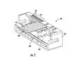
- Figures 4 and 5 illustrate a connector assembly 150 including a low insertion force connector 164 in an open position ( Figure 4) and in a closed connection (Figure 5).
- the low insertion force connector 164 is an example of an internal connector suitable for use as the internal connector 42 of Figure 1.
- the connector assembly 150 has a housing 152 that can be positioned in a wall of the housing of a mobile terminal such that the low insertion force connector 164 extends into the housing of the mobile terminal and forms an electrical connection with a flexible printed circuit 170 (as shown in Figure 5).
- the low insertion force connector 164 includes a lower locking mechanism 156, an upper lever 154, and low insertion force conductive leads 162.
- the housing 152 includes slots 158 for containing auxiliary connector conductive leads 160.
- the auxiliary connector conductive leads 160 are configured to be electrically connected to a mating connector of the auxiliary device (not shown) and to the low insertion force conductive leads 162.
- the housing 152 rigidly couples the low insertion force connector leads 162 to the auxiliary connector side of the connector assembly 150.
- the housing 152 is a unitary molded polymeric body; however, any suitable material or housing configuration, including multiple housing pieces, can be used.
- the low insertion force conductive leads 162 are exposed.
- a cover may be placed over the low insertion force conductive leads 162, for example, to protect the leads 162 from wear.
- the flexible printed circuit 170 includes leads 172 that form an electrical connection with the low insertion force conductive leads 162 when the upper lever 154 and the lower locking mechanism 156 are in the closed position ( Figure 5).
- the upper lever 154 and the lower locking mechanism 156 apply tangential force (a vertical direction as shown in Figure 5) to the flexible printed circuit 170 to assist in the formation of the electrical connection between the circuit board leads 172 and the low insertion force conductive leads 162.
- the low insertion force connector 164 can release or receive the flexible printed circuit 170.
- any suitable low insertion force connector or zero insertion force connector can be used for the low insertion force connector 164.
- the upper lever 154 can be omitted, and the electrical connection can be maintained using the lower locking mechanism 156, which may include a movable spring clip mechanism.
- the lower locking mechanism 156 can be omitted, and the upper lever 154 can be modified to lock from above into a closed position to maintain the electrical connection.
- Figures 6 and 7 illustrate a connector assembly 200 including a snap connector 204 in an open position ( Figure 6) and in a closed connection ( Figure 7).
- the snap connector 204 is an example of an internal connector suitable for use as the internal connector 42 of Figure 1 in further embodiments of the present invention.
- the connector assembly 200 includes a unitary housing 202 that can be positioned in a wall of the housing of a mobile terminal.
- the housing 202 has slots 212 that include auxiliary conductive leads 214, which define auxiliary contact on an outside wall of the housing 202.
- the snap connector 204 is molded as a unitary part of the housing 202 of the connector assembly 200.
- the snap connector 204 has lower snap connector conductive leads 210 that electrically connect to the auxiliary conductive leads 214 inside the housing 202.
- the snap connector 204 forms an electrical connection with a flexible printed circuit 206.
- the flexible printed circuit 206 includes a mating snap connection 208 that includes upper snap connector conductive leads 222.
- the flexible printed circuit 206 includes flexible printed circuit leads 224 that are electrically connected to the upper snap connector conductive leads 222.
- the upper snap connector conductive leads 222 are electrically connected to the lower snap connector conductive leads 210.
- an electrical connection can be made from the auxiliary conductive leads 214 to the flexible printed circuit leads 224 through the lower snap connector conductive leads 222 and the upper snap connector conductive leads 210.
- FIG 8 illustrates further embodiments of a connector assembly 300 according to the present invention.
- the connector assembly 300 includes a housing 308 for housing a low insertion force connector 320.
- the low insertion force connector 320 can have a configuration similar to the low insertion force connector 164 described with respect to Figures 4 and 5; however, as illustrated in Figure 8, the low insertion force connector 320 has a lower locking mechanism 312 or an upper locking mechanism 314.
- the low insertion force connector 320 includes electrical contact(s) 306, some of which are shown in Figure 8.
- the electrical contact(s) 306 have an upper portion 326 and a lower portion 328 that define an opening into which a flexible printed circuit 302 can be inserted.
- the lower locking mechanism 312 is movable between an open position 322 and a closed position 324 to hold the flexible printed circuit 302 in the electrical contact 306.
- the upper locking mechanism 314 can be moved downward to a closed position to apply a downward force to the electrical contact 306 to maintain an electrical connection to the flexible printed circuit 302.
- the electrical contact 306 in the low insertion force connector 320 is electrically connected to an elastomer contact 304.
- the elastomer contact 304 is a compliant elastomer contact that can include a conductive material, such as gold or silver particles, suspended in an elastomeric material to provide a conductive path when axial pressure is applied to the elastomer.
- the elastomer contact 304 can have a plurality of conductive paths configured so that each conductive path is electrically connected to a different internal electrical contact, such as the electrical contact 306 illustrated in Figure 8.
- An example of a suitable conductive elastomer material is a silicone rubber strip including sequentially spaced conductive and non-conductive (insulating) material to form a plurality of conductive paths.
- an elastomer material is a silicone elastomer core having embedded metal strips.
- Elastomer contacts are commercially available, for example, from Fujipoly Polymer Industries Co., Ltd., Tokyo, Japan under the trade name ZEBRA TM , such as ZEBRA TM Gold 8000. Elastomer contacts may provide a relatively large number of conductive paths in a small area. As illustrated, the elastomer contact 304 can provide a seal between the opening 316 and the low insertion force connector 320 that may protect the low insertion force connector 320 and electrical circuits inside the portable housing from outside particles, such as dust and dirt contamination.
- the housing 308 defines an opening 316 into which an electrical contact (not shown), such as a contact from an accessory device for a mobile communications device, can be inserted.
- an electrical contact such as a contact from an accessory device for a mobile communications device
- the elastomer contact 304 is compressed when an electrical contact is inserted into the opening 316 to provide conductivity to the electrical contact 306.
- Other suitable contacts can be used, such as metal spring contacts and flexible spring contacts.
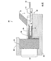
- the connector assembly 400 includes a housing 410 that defines an opening for an auxiliary device mating connector.
- An electrical contact 412 is positioned in the housing and is electrically connected to an elastomer contact 418.
- a guiding grove 414 is positioned adjacent the electrical contact 412 so that the guiding grove 414 and the electrical contact 412 together define an opening into which a flexible printed circuit 402 can be inserted.
- the flexible printed circuit 402 is electrically connected to an electrical circuit 404, for example, a printed circuit board in a portable electronic device, such as a radiotelephone, smart phone, or other hand held device.
- the connector assembly 400 is placed on a lower portion 408 of the portable housing.
- An upper portion 406 of the portable housing can be placed over the connector assembly 400.
- the upper and lower housing 406, 408 can be the housing of a portable electronic device such as a radiotelephone, smart phone, or hand held device or a separate housing structure that is, in turn, positioned in a device housing.
- the lower housing 408 includes a fastener 420 that can be placed through openings 422 and 424 to fasten the upper housing 406 against the top of the connector assembly 400.
- the upper housing 406 places downward pressure on the flexible printed circuit 402 to hold the flexible printed circuit 402 in electrical contact with the electrical contacts 412.
- FIG 10 illustrates a connector assembly 500 according to the still further embodiments of the present invention.
- the connector assembly 500 is positioned between an upper housing 522 and a lower housing 520 of a portable electronic device.
- An electrical circuit 512 is placed between the upper housing 522 and the lower housing 520.
- a flexible printed circuit 510 provides an electrical connection between the electrical circuit 512 and the connector assembly 500.
- the connector assembly 500 has a housing 502 that defines an opening 508 through which an elastomer contact 506 is accessible from the outside of the upper housing 522 and the lower housing 520.
- the elastomer contact 506 is electrically connected to an electrical contact 516 that provides an electrical connection between the flexible printed circuit 510 and the elastomer contact 506.
- a conductive adhesive 514 maintains the electrical connection between the flexible printed circuit 510 and the elastomer contact 506.
- the conductive adhesive 514 can be an anisotropic conductive adhesive such as 3M TM Z-Axis Adhesive Film from 3M Company, St. Paul, MN, U.S.A.
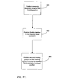
- portable devices can be assembled according to the operations illustrated in Figure 11.
- a connector assembly such as the connector assembly 400 shown in Figure 9, is positioned in a wall of a housing portion, such as housing portion 408.
- a flexible connector is positioned in a low insertion force connector of the connector assembly.
- a second housing portion is positioned on the first housing portion to move the low insertion force to a closed position.
- the flexible printed circuit 402 is placed on electrical contacts 412.
- the upper housing portion 406 can be placed on the lower housing portion 408 to apply a downward pressure on the flexible printed circuit 402 to retain the flexible printed circuit 402 in electrical contact with the electrical contacts 412.
Landscapes
- Telephone Set Structure (AREA)
- Coupling Device And Connection With Printed Circuit (AREA)
- Details Of Connecting Devices For Male And Female Coupling (AREA)
Claims (24)
- Eine tragbare elektronische Vorrichtung, enthaltend:ein tragbares Gehäuse (12),eine elektrische Schaltung (30), die im Gehäuse (12) positioniert ist; undeine Steckverbindung (40), die in eine Wand des Gehäuses (12) positioniert ist, wobei die Steckverbindung (40) enthält:einen internen Stecker (42), der sich in das Gehäuse (12) hinein ausdehnt;einen Hilfsstecker (54), der mit dem internen Stecker (42) fest verbunden ist und von außerhalb des Gehäuses (12) zugreifbar ist, wobei der Hilfsstecker (54) elektrisch mit dem internen Stecker (42) verbunden ist; undein Verbindungsgehäuseteil, das den internen Stecker (42) und den Hilfsstecker (54) fest verbindet;darin gekennzeichnet, dass die tragbare elektronische Vorrichtung enthält:ein flexibles Teil (32), das den internen Stecker (42) mit der elektrischen Schaltung (30) elektrisch verbindet, wobei das flexible Teil (32) konfiguriert ist, um weniger als 10% einer äußeren Druckkraft auf die Steckverbindung zur elektrischen Schaltung (30) zu übertragen.
- Die Vorrichtung das Anspruchs 1, worin der interne Stecker (42) einen Stecker mit niedriger Einschubskraft enthält.
- Die Vorrichtung des Anspruchs 2, worin das flexible Teil (32) eine flexible gedruckte Schaltung enthält.
- Die Vorrichtung des Anspruchs 3, worin das Verbindungsgehäuseteil ein durchgehend gegossenes, polymeres Gehäuseteil ist.
- Die Vorrichtung des Anspruchs 4, worin der Stecker (42) mit geringer Einschubskraft und der Hilfsstecker (54) jeweils eine Vielzahl von elektrisch isolierten, elektrischen Kontaktpunkten enthält und worin die Steckverbindung (40) weiterhin eine Vielzahl von leitenden Teilen (50) enthält, die sich zwischen die jeweils entsprechenden elektrischen Kontaktpunkte ausdehnen, und die ein erstes Ende besitzen, einen elektrischen Kontakt im Stecker mit geringer Einschubskraft definierend und ein zweites Ende, einen assoziierten elektrischen Kontakt im Hilfsstecker definierend.
- Die Vorrichtung des Anspruchs 5, worin die Vielzahl der leitenden Teile (50) metallische Federstecker enthält.
- Die Vorrichtung des Anspruchs 6, worin die elektrischen Kontaktpunkte im Hilfsstecker (54) flache Federverbindungen enthalten, die durch ein Ende der metallischen Federstecker begrenzt werden.
- Die Vorrichtung des Anspruchs 5, worin die elektrischen Kontaktpunkte im Hilfsstecker (54) Standardkunststoffkontakte enthalten.
- Die Vorrichtung des Anspruchs 8, worin die Standardkunststoffkontakte ein Kunststoffmaterial enthalten, das darin schwebende Goldpartikel besitzt.
- Die Vorrichtung des Anspruchs 5, worin die Vielzahl der leitenden Teile (50) leitende Bahnen im Polymergehäuseteil enthält, die von leitenden Kunststoffzwischenverbindungen gebildet werden.
- Die Vorrichtung des Anspruchs 10, weiterhin eine Vielzahl von metallischen, elektrischen Kontakten enthaltend, die mit den Enden der leitenden Bahnen benachbart zum Stecker mit geringer Einschubskraft verbunden sind, um die elektrischen Kontaktpunkte im Stecker mit geringer Einschubskraft festzulegen.
- Die Vorrichtung des Anspruchs 1, worin der interne Stecker (42) einen Schnappstecker enthält.
- Die Vorrichtung des Anspruchs 12, worin der Schnappstecker und der Hilfsstecker (54) jeweils ein Vielzahl von elektrisch isolierten, elektrischen Kontaktpunkten enthalten und worin die Steckverbindung (40) weiterhin eine Vielzahl von leitenden Teilen enthält, die sich zwischen die entsprechenden elektrischen Kontaktpunkte ausdehnen und ein erstes Ende besitzen, das einen elektrischen Kontakt im Schnappstecker festlegt, und ein zweites Ende, das einen assoziierten elektrischen Kontakt im Hilfsstecker festlegt.
- Die Vorrichtung des Anspruchs 1, worin die elektrische Schaltung (30) eine Leiterplatte einschließlich eines Prozessors und eines Prozessorsystembusses enthält und worin der Hilfsstecker ein Interface zwischen dem Systembus und einer Hilfsvorrichtung enthält, um die Hilfsvorrichtung operativ mit dem Prozessor zu koppeln.
- Die Vorrichtung des Anspruches 14, worin die Vorrichtung ein drahtloses Terminal enthält und worin die Leiterplatte weiterhin eine drahtlose Kommunikationsschaltung enthält.
- Die Vorrichtung des Anspruches 2, worin der Stecker mit der geringen Einschubskraft einen ersten Teil und einen zweiten Teil enthält, wobei der zweite Teil zwischen einer ersten Position, die den flexiblen Teil im Stecker mir der geringen Einschubskraft festhält, und einer zweiten Position, die den flexiblen Teil aus dem Stecker mit der geringen Einschubskraft entlässt, beweglich ist.
- Die Vorrichtung des Anspruches 16, worin der Leiter mit der geringen Einschubskraft weiterhin einen Lockmechanismus enthält, der konfiguriert ist, um den zweiten Teil des Steckers mit der geringen Einschubskraft zwischen der ersten Position und der zweiten Position zu bewegen.
- Die Vorrichtung des Anspruchs 1, worin der Hilfsstecker (54) weiterhin einen Stromanschluss enthält.
- Die Vorrichtung des Anspruchs 1, worin der Hilfsstecker (54) weiterhin einen Audioanschluss enthält.
- Die Vorrichtung des Anspruchs 1, worin die Steckverbindung eine Höhe von zwischen etwa 3mm und etwa 4mm besitzt.
- Die Vorrichtung des Anspruchs 1, worin der interne Stecker (42) einen anisotropen, leitenden Kleber enthält, der eine elektrische Verbindung zwischen dem flexiblen Teil (32) und dem internen Stecker (42) herstellt.
- Die Vorrichtung des Anspruchs 1, worin die Vorrichtung ein Funktelefon ist.
- Ein Verfahren zur Verbindung einer Steckverbindung (40), einen Stecker mit geringer Einschubskraft besitzend, mit einem flexiblen Teil (32) in einer tragbaren elektronischen Vorrichtung, wobei die tragbare elektronische Vorrichtung ein erstes Gehäuseteil (20A) und ein zweites Gehäuseteil (20B) enthält, und wobei das Verfahren enthält:das Positionieren einer Steckverbindung (40) in eine Wand des ersten Gehäuseteils der tragbaren elektronischen Vorrichtung, wobei die Steckverbindung (40) enthält:einen Stecker (42) mit geringer Einschubskraft der einen ersten und einen zweiten Teil enthält, wobei der zweite Teil zwischen einer geschlossenen Position und einer offenen Position beweglich ist; undeinen Hilfsstecker (54), der fest an den Stecker (42) mit geringer Einschubskraft gekoppelt ist und von außerhalb des Gehäuses zugänglich ist, wobei der Hilfsstecker (54) elektrisch mit dem Stecker (42) mit geringer Einschubskraft verbunden ist; unddas Positionieren des zweiten Gehäuseteils (20B) der tragbaren elektronischen Vorrichtung auf ein erstes Gehäuseteil (20A) der tragbaren elektronischen Vorrichtung, um den zweiten Teil des Steckers mit der geringen Einschubskraft von der offenen in die geschlossene Position zu bewegen, um den flexiblen Teil im Stecker mit der geringen Einschubskraft zu halten.
- Ein drahtloses Terminal, enthaltend:ein tragbares Gehäuse (12);eine elektrische Schaltung (30), im Gehäuse positioniert, wobei die elektrische Schaltung (30) eine drahtlose Kommunikationsschaltung auf einer Leiterplatte einschließlich eines Prozessors und eines Prozessorbusses enthält;eine Steckverbindung (40), mit einer Höhe kleiner als etwa 5mm, positioniert in eine Wand des Gehäuses (12), wobei die Steckverbindung (40) enthält:einen internen Stecker (42), der sich in das Gehäuse (12) ausdehnt;einen Hilfsstecker (54), der mit dem internen Stecker (42) fest verbunden ist und von außerhalb des Gehäuses (12) erreichbar ist, wobei der Hilfsstecker (54) elektrisch mit dem internen Stecker (42) verbunden ist; undworin der interne Stecker (42) und der Hilfsstecker (54) jeweils eine Vielzahl von elektrisch isolierten, elektrischen Kontaktpunkten enthalten und worin die Steckverbindung (40) weiterhin eine Vielzahl von leitenden Teilen (50) enthält, die sich zwischen die entsprechenden elektrischen Kontaktpunkte ausdehnen und ein erstes Ende besitzen, das einen elektrischen Kontakt im internen Stecker (42) festlegt, und ein zweites Ende, das einen assoziierten elektrischen Kontakt im Hilfsstecker (58) definiert, wobei die Vielzahl der Teile (50) leitende Bahnen enthält, die durch leitende Kunststoffzwischenverbindungen geformt werden;darin gekennzeichnet, dass das drahtlose Terminal einen flexiblen Teil (32) enthält, der den internen Stecker (42) elektrisch mit der elektrischen Schaltung (30) verbindet, wobei der flexible Teil (32) konfiguriert ist, um weniger als etwa 10% einer äußeren Druckkraft auf die Steckverbindung (40) zur elektrischen Schaltung (30) zu übertragen.
Applications Claiming Priority (2)
| Application Number | Priority Date | Filing Date | Title |
|---|---|---|---|
| US10/456,322 US6840796B2 (en) | 2003-06-06 | 2003-06-06 | Portable electronic devices with a flexible connection between internal electronics and an auxiliary connection |
| PCT/IB2004/000112 WO2004110121A1 (en) | 2003-06-06 | 2004-01-14 | Portable electronic devices with a flexible connection between internal electronics and an auxiliary connection |
Publications (2)
| Publication Number | Publication Date |
|---|---|
| EP1632115A1 EP1632115A1 (de) | 2006-03-08 |
| EP1632115B1 true EP1632115B1 (de) | 2007-07-04 |
Family
ID=33490137
Family Applications (1)
| Application Number | Title | Priority Date | Filing Date |
|---|---|---|---|
| EP04702014A Expired - Lifetime EP1632115B1 (de) | 2003-06-06 | 2004-01-14 | Tragbares elektronisches gerät mit flexibler verbindung zwischen interner elektronik und einer hilfsverbindung |
Country Status (6)
| Country | Link |
|---|---|
| US (1) | US6840796B2 (de) |
| EP (1) | EP1632115B1 (de) |
| JP (1) | JP4638414B2 (de) |
| CN (1) | CN100475007C (de) |
| DE (1) | DE602004007385T2 (de) |
| WO (1) | WO2004110121A1 (de) |
Families Citing this family (18)
| Publication number | Priority date | Publication date | Assignee | Title |
|---|---|---|---|---|
| KR100490356B1 (ko) * | 2003-01-20 | 2005-05-17 | 삼성전자주식회사 | 휴대용 무선 단말기의 로터리형 힌지 장치 |
| US7165015B2 (en) * | 2005-03-29 | 2007-01-16 | Cryovac, Inc. | Handheld device for retrieving and analyzing data from an electronic monitoring device |
| JP2006294350A (ja) * | 2005-04-07 | 2006-10-26 | Three M Innovative Properties Co | ケーブルハーネス体 |
| JP4491393B2 (ja) * | 2005-09-27 | 2010-06-30 | 富士通株式会社 | 携帯端末装置 |
| JP4822983B2 (ja) * | 2006-08-23 | 2011-11-24 | モレックス インコーポレイテド | 中継コネクタ |
| US8154877B2 (en) * | 2007-10-23 | 2012-04-10 | Psion Teklogix Inc. | Expansion system for portable electronic devices |
| WO2011103874A1 (en) * | 2010-02-25 | 2011-09-01 | Estron A/S | Solderless connector for microelectronics |
| US8506334B2 (en) * | 2010-09-30 | 2013-08-13 | Apple Inc. | Battery connector with lid for easy disconnect |
| CN102522047A (zh) * | 2011-12-12 | 2012-06-27 | 中国航空无线电电子研究所 | 一种轻型机载智能多功能显示器 |
| US8672714B2 (en) * | 2011-12-28 | 2014-03-18 | Hsing Chau Industrial Co., Ltd. | HDMI audio-video signal switching device |
| US8548397B1 (en) * | 2012-04-26 | 2013-10-01 | Harris Corporation | Mobile wireless communications device including a power module coupled to a wireless module and associated methods |
| TWI504330B (zh) * | 2012-05-16 | 2015-10-11 | Dexin Corp | 保護殼 |
| US8804354B2 (en) * | 2012-09-11 | 2014-08-12 | Apple Inc. | Load sharing device and I/O architecture against imparted abuse loads |
| JP6088958B2 (ja) * | 2013-10-29 | 2017-03-01 | 京セラ株式会社 | 防水コネクタ構造を具えた電子機器 |
| DE102013018829A1 (de) * | 2013-11-09 | 2015-05-13 | Brose Fahrzeugteile Gmbh & Co. Kommanditgesellschaft, Hallstadt | Kapazitiver Sensor für ein Fahrzeug |
| CN104717334A (zh) * | 2015-03-30 | 2015-06-17 | 宁波保税区攀峒信息科技有限公司 | 一种以刚性体连接方式进行外部扩展的移动终端 |
| DE102016106704A1 (de) | 2016-04-12 | 2017-10-12 | HARTING Electronics GmbH | Steckverbinder mit Leitgummi |
| CN106654728B (zh) | 2016-11-14 | 2019-02-05 | 华为技术有限公司 | 一种连接器及通信设备 |
Family Cites Families (23)
| Publication number | Priority date | Publication date | Assignee | Title |
|---|---|---|---|---|
| US3648002A (en) | 1970-05-04 | 1972-03-07 | Essex International Inc | Current control apparatus and methods of manufacture |
| JPS5722712Y2 (de) | 1978-08-07 | 1982-05-17 | ||
| EP0221924A1 (de) | 1985-04-30 | 1987-05-20 | AMP INCORPORATED (a New Jersey corporation) | Biegsames elektrisches brückenkabel und zusammenbau |
| NL8503347A (nl) | 1985-12-04 | 1987-07-01 | Du Pont Nederland | Connector. |
| US5006286A (en) | 1986-03-31 | 1991-04-09 | Amp Incorporated | Polymeric electrical interconnection apparatus and method of use |
| JPS6332881A (ja) | 1986-07-25 | 1988-02-12 | 日本テキサス・インスツルメンツ株式会社 | Icソケツト |
| JPS63300652A (ja) * | 1987-05-30 | 1988-12-07 | Fujitsu Ltd | 送受話器の構造 |
| JP2856263B2 (ja) * | 1990-09-07 | 1999-02-10 | 富士通株式会社 | 携帯電話機 |
| DE69230913T2 (de) | 1991-07-16 | 2000-12-07 | Berg Electronics Manufacturing B.V., S'-Hertogenbosch | Flachbau-, oberflächenmontierter Steckverbinder mit gekrümmten freitragendenKontaktfedern. |
| JP2756055B2 (ja) * | 1992-06-05 | 1998-05-25 | 富士通株式会社 | 無線端末装置の外部インタフェース用コネクタ |
| US5521336A (en) * | 1994-05-23 | 1996-05-28 | International Business Machines Corporation | Simplified digital pad sensor |
| US5517683A (en) * | 1995-01-18 | 1996-05-14 | Cycomm Corporation | Conformant compact portable cellular phone case system and connector |
| JP2913156B2 (ja) * | 1996-02-21 | 1999-06-28 | 日本航空電子工業株式会社 | シールド機構付き中継コネクタ |
| US5846094A (en) | 1996-02-29 | 1998-12-08 | Motorola, Inc. | Electrical coupling method and apparatus for printed circuit boards including a method of assembly |
| US5830012A (en) * | 1996-08-30 | 1998-11-03 | Berg Technology, Inc. | Continuous plastic strip for use in manufacturing insulative housings in electrical connectors |
| GB9704118D0 (en) | 1997-02-27 | 1997-04-16 | Amp Holland | Electrical interconnection for mobile phones |
| US6658268B1 (en) * | 1998-05-01 | 2003-12-02 | Motorola, Inc. | Enhanced companion digital organizer for a cellular phone device |
| JP2000030784A (ja) | 1998-05-08 | 2000-01-28 | Japan Aviation Electronics Ind Ltd | 電気コネクタ |
| SG90078A1 (en) | 1999-11-15 | 2002-07-23 | Creative Tech Ltd | Docking interface for portable device |
| US20020186551A1 (en) | 2000-02-24 | 2002-12-12 | Toru Murowaki | Electronic control unit having flexible wires connecting connector to circuit board |
| US6461169B1 (en) | 2001-05-04 | 2002-10-08 | Intel Corporation | Interconnecting circuit modules to a motherboard using an edge connector with conductive polymer contacts |
| JP2003069180A (ja) * | 2001-08-21 | 2003-03-07 | Canon Inc | フレキシブルブリント基板および電子機器 |
| JP2003133678A (ja) * | 2001-10-30 | 2003-05-09 | Nec Saitama Ltd | フレキシブル基板とプリント配線板の接続構造 |
-
2003
- 2003-06-06 US US10/456,322 patent/US6840796B2/en not_active Expired - Lifetime
-
2004
- 2004-01-14 CN CNB2004800155098A patent/CN100475007C/zh not_active Expired - Fee Related
- 2004-01-14 WO PCT/IB2004/000112 patent/WO2004110121A1/en not_active Ceased
- 2004-01-14 EP EP04702014A patent/EP1632115B1/de not_active Expired - Lifetime
- 2004-01-14 JP JP2006508404A patent/JP4638414B2/ja not_active Expired - Fee Related
- 2004-01-14 DE DE602004007385T patent/DE602004007385T2/de not_active Expired - Lifetime
Non-Patent Citations (1)
| Title |
|---|
| None * |
Also Published As
| Publication number | Publication date |
|---|---|
| WO2004110121A1 (en) | 2004-12-16 |
| CN100475007C (zh) | 2009-04-01 |
| JP2006527517A (ja) | 2006-11-30 |
| US6840796B2 (en) | 2005-01-11 |
| DE602004007385T2 (de) | 2007-11-08 |
| US20040248461A1 (en) | 2004-12-09 |
| EP1632115A1 (de) | 2006-03-08 |
| CN1799295A (zh) | 2006-07-05 |
| JP4638414B2 (ja) | 2011-02-23 |
| DE602004007385D1 (de) | 2007-08-16 |
Similar Documents
| Publication | Publication Date | Title |
|---|---|---|
| EP1632115B1 (de) | Tragbares elektronisches gerät mit flexibler verbindung zwischen interner elektronik und einer hilfsverbindung | |
| US6902425B2 (en) | Electrical connector for flexible printed circuit board | |
| CN100395922C (zh) | 接口部件、插头以及接口部件与插头的连接方法 | |
| CN110061375B (zh) | 连接器、对接连接器以及连接器组件 | |
| US8000104B2 (en) | Electronic device having electrostatic discharge function | |
| GB2390756A (en) | PCB-mounted switch of a connector | |
| EP1199777B1 (de) | Elektrische Steckverbindungsvorrichtung, Batterie mit dieser Vorrichtung und elektronisches Gerät mit einer Batterie | |
| US7445506B2 (en) | Shielded connector | |
| CN102227849A (zh) | 用于安装在印刷电路板上的挠性电连接器 | |
| EP1626450B1 (de) | Vorrichtung zum lösbaren Anbringen einer Batterie an ein mobiles Gerät | |
| WO2008083166A2 (en) | Electrical connector with grounding pin | |
| CN100377446C (zh) | 电连接插头以及与之连接的接口部件 | |
| KR101438582B1 (ko) | 고전류 전기 커넥터 | |
| CN100524955C (zh) | 用于数字照相机模块的插座 | |
| US7744413B2 (en) | Metal module housing for mounting on a printed circuit board | |
| JP2011029266A (ja) | 外付ユニットの取付構造 | |
| CN204011866U (zh) | 连接器 | |
| US6428347B1 (en) | Electrical compression connection for retractable connectors | |
| KR100799439B1 (ko) | 메모리카드용 어댑터 | |
| KR102397522B1 (ko) | 커넥터 어셈블리 | |
| CN112952414A (zh) | 电子设备 | |
| JP2000323197A (ja) | コネクタターミナル | |
| WO2005008841A1 (ja) | コネクタ | |
| US6002595A (en) | Cable-to-board assemblies | |
| JP4579141B2 (ja) | 携帯端末 |
Legal Events
| Date | Code | Title | Description |
|---|---|---|---|
| PUAI | Public reference made under article 153(3) epc to a published international application that has entered the european phase |
Free format text: ORIGINAL CODE: 0009012 |
|
| 17P | Request for examination filed |
Effective date: 20051229 |
|
| AK | Designated contracting states |
Kind code of ref document: A1 Designated state(s): DE FR GB |
|
| DAX | Request for extension of the european patent (deleted) | ||
| RBV | Designated contracting states (corrected) |
Designated state(s): DE FR GB |
|
| GRAP | Despatch of communication of intention to grant a patent |
Free format text: ORIGINAL CODE: EPIDOSNIGR1 |
|
| GRAS | Grant fee paid |
Free format text: ORIGINAL CODE: EPIDOSNIGR3 |
|
| GRAA | (expected) grant |
Free format text: ORIGINAL CODE: 0009210 |
|
| AK | Designated contracting states |
Kind code of ref document: B1 Designated state(s): DE FR GB |
|
| REG | Reference to a national code |
Ref country code: GB Ref legal event code: FG4D |
|
| REF | Corresponds to: |
Ref document number: 602004007385 Country of ref document: DE Date of ref document: 20070816 Kind code of ref document: P |
|
| ET | Fr: translation filed | ||
| PLBE | No opposition filed within time limit |
Free format text: ORIGINAL CODE: 0009261 |
|
| STAA | Information on the status of an ep patent application or granted ep patent |
Free format text: STATUS: NO OPPOSITION FILED WITHIN TIME LIMIT |
|
| 26N | No opposition filed |
Effective date: 20080407 |
|
| REG | Reference to a national code |
Ref country code: FR Ref legal event code: PLFP Year of fee payment: 13 |
|
| REG | Reference to a national code |
Ref country code: FR Ref legal event code: PLFP Year of fee payment: 14 |
|
| REG | Reference to a national code |
Ref country code: FR Ref legal event code: PLFP Year of fee payment: 15 |
|
| PGFP | Annual fee paid to national office [announced via postgrant information from national office to epo] |
Ref country code: FR Payment date: 20171229 Year of fee payment: 15 |
|
| PGFP | Annual fee paid to national office [announced via postgrant information from national office to epo] |
Ref country code: DE Payment date: 20180103 Year of fee payment: 15 Ref country code: GB Payment date: 20180110 Year of fee payment: 15 |
|
| REG | Reference to a national code |
Ref country code: DE Ref legal event code: R119 Ref document number: 602004007385 Country of ref document: DE |
|
| GBPC | Gb: european patent ceased through non-payment of renewal fee |
Effective date: 20190114 |
|
| PG25 | Lapsed in a contracting state [announced via postgrant information from national office to epo] |
Ref country code: DE Free format text: LAPSE BECAUSE OF NON-PAYMENT OF DUE FEES Effective date: 20190801 Ref country code: FR Free format text: LAPSE BECAUSE OF NON-PAYMENT OF DUE FEES Effective date: 20190131 |
|
| PG25 | Lapsed in a contracting state [announced via postgrant information from national office to epo] |
Ref country code: GB Free format text: LAPSE BECAUSE OF NON-PAYMENT OF DUE FEES Effective date: 20190114 |