EP1632183B1 - Ultraschallgerät - Google Patents
Ultraschallgerät Download PDFInfo
- Publication number
- EP1632183B1 EP1632183B1 EP04746011A EP04746011A EP1632183B1 EP 1632183 B1 EP1632183 B1 EP 1632183B1 EP 04746011 A EP04746011 A EP 04746011A EP 04746011 A EP04746011 A EP 04746011A EP 1632183 B1 EP1632183 B1 EP 1632183B1
- Authority
- EP
- European Patent Office
- Prior art keywords
- generation means
- waveform
- ultrasound
- duty factor
- mode
- Prior art date
- Legal status (The legal status is an assumption and is not a legal conclusion. Google has not performed a legal analysis and makes no representation as to the accuracy of the status listed.)
- Expired - Lifetime
Links
Images



Classifications
-
- A—HUMAN NECESSITIES
- A61—MEDICAL OR VETERINARY SCIENCE; HYGIENE
- A61B—DIAGNOSIS; SURGERY; IDENTIFICATION
- A61B8/00—Diagnosis using ultrasonic, sonic or infrasonic waves
-
- B—PERFORMING OPERATIONS; TRANSPORTING
- B06—GENERATING OR TRANSMITTING MECHANICAL VIBRATIONS IN GENERAL
- B06B—METHODS OR APPARATUS FOR GENERATING OR TRANSMITTING MECHANICAL VIBRATIONS OF INFRASONIC, SONIC, OR ULTRASONIC FREQUENCY, e.g. FOR PERFORMING MECHANICAL WORK IN GENERAL
- B06B1/00—Methods or apparatus for generating mechanical vibrations of infrasonic, sonic, or ultrasonic frequency
- B06B1/02—Methods or apparatus for generating mechanical vibrations of infrasonic, sonic, or ultrasonic frequency making use of electrical energy
- B06B1/0207—Driving circuits
- B06B1/0215—Driving circuits for generating pulses, e.g. bursts of oscillations, envelopes
-
- A—HUMAN NECESSITIES
- A61—MEDICAL OR VETERINARY SCIENCE; HYGIENE
- A61B—DIAGNOSIS; SURGERY; IDENTIFICATION
- A61B2560/00—Constructional details of operational features of apparatus; Accessories for medical measuring apparatus
- A61B2560/02—Operational features
- A61B2560/0204—Operational features of power management
- A61B2560/0214—Operational features of power management of power generation or supply
Definitions
- the present invention relates to an ultrasound diagnostic device used in the medical field.
- Document JP 3-262466 A discloses an ultrasonic diagnostic apparatus in which in transmitting/receiving systems, a burst wave number/duty ratio setting circuit is provided between a pulse generator and transmission delaying circuits, to variably set the number of burst waves and a duty ratio.
- the setting circuit converts a burst frequency band to a narrow band by increasing the number of burst waves.
- a matched filter extracts only a frequency band converted to a narrow band.
- Document JP 7-67877 A discloses an ultrasonic diagnostic apparatus in which a control circuit changes certain conditions in response to a change of other conditions, so that an initially set output level is maintained.
- Document JP 7-155324 A discloses an ultrasonic diagnostic apparatus in which a transmission pulse duty converter supplies a transmission pulse whose transmission pulse duty in the Doppler mode is smaller than in the B-mode.
- a driver amplifies the pulse to a set voltage, and supplies it to the ultrasonic probe, so that a testee body is radiated with an ultrasonic pulse.
- a B-mode image and Doppler information are obtained from an echo signal from the testee body. The B-mode and the Doppler mode are switched periodically.
- Patent document US 6,432,055 B1 discloses an ultrasonic diagnostic apparatus in which a three-state, pulse width modulated, bipolar waveform is constructed by summing a first component with an inverted, time-shifted version of the first component. The time interval for the shift is selectable.
- the three-state waveform is generated by a switched voltage source that provides a low, constant source impedance for all three voltage states.
- Patent document US 5,509,413 discloses an ultrasonic diagnostic apparatus in which an ultrasonic probe driving unit can apply a stepwise varying drive voltage to the ultrasonic probe.
- the drive voltage is selectively set by a setting unit so as to allow the output level of the ultrasonic probe to be in a range near an upper limit.
- ultrasound diagnostic devices employ modes called the B-mode, the M-mode, the Doppler mode (hereinafter referred to as D-mode) and the color or two-dimensional Doppler mode (hereinafter referred to as C-mode) alone or in combination.
- a transmission power is controlled so that a surface temperature of a portion of an ultrasound generation means contacting with a living body and an acoustic power from the ultrasound generation means to a living body do not exceed predetermined levels.
- the transmission is conducted with a frequency, an amplitude and a wave number of a driving waveform that are determined for each mode.
- a transmission power is controlled appropriately to have a predetermined value without excess and deficiency.
- Fig. 7 is a block diagram showing an exemplary configuration of a conventional ultrasound diagnostic device.
- the conventional ultrasound diagnostic device is composed of: an ultrasound generation means 71; a waveform generation means 72; a mode control unit 75; a waveform control unit 74 and a voltage-variable power supply unit 73.
- the ultrasound generation means 71 transmits ultrasound.
- the waveform generation means 72 generates a single pulse or a burst pulse to drive the ultrasound generation means 71.
- the mode control unit 75 generates mode information concerning the mode of transmission.
- the waveform control unit 74 controls an amplitude and a wave number of a driving waveform that is generated by the waveform generation means 72 based on the mode information from the mode control unit 75, and controls the amplitude by using a power supply voltage.
- the voltage-variable power supply unit 73 determines the amplitude of the driving waveform that is generated by the waveform generation means 72.
- the voltage-variable power supply unit 73 of the ultrasound diagnostic device a power supply ready for a high voltage exceeding several tens to hundreds volts is necessary and in order to allow for a change in voltage between the respective modes, a quick response at several tens ⁇ -seconds is required.
- a quick-response circuit is employed, switching among a plurality of power supplies that generate different voltages is performed, or a plurality of waveform generation means with different output levels is provided in parallel with each other so as to choose a proper one for each mode.
- the power supply unit is increased in size, which causes the problems of an increase in cost and size of the device and moreover deterioration of the reliability.
- a first aspect of the ultrasound diagnostic device includes: an ultrasound generation unit that transmits ultrasound; a waveform generation unit that generates a single pulse or a burst pulse whose duty factor is variable so as to drive the ultrasound generation unit; and a power supply unit that determines an amplitude of a driving waveform generated by the waveform generation unit.
- a second aspect of the ultrasound diagnostic device includes: an ultrasound generation unit that transmits ultrasound; a waveform generation unit that generates a single pulse or a burst pulse whose duty factor is variable in units of a time that is a period corresponding to a frequency outside a frequency band of the ultrasound generation unit so as to drive the ultrasound generation unit; and a power supply unit that determines an amplitude of a driving waveform generated by the waveform generation unit.
- an acoustic power of the ultrasound transmitted from the ultrasound generation unit can be controlled without making the transmission amplitude variable, and an unnecessary increase of harmonics due to the change of duty factor can be suppressed. Therefore, an increase of the acoustic power and an increase of a surface temperature, which result from the transmission of unnecessary energy, can be suppressed as well.
- a third aspect of the ultrasound diagnostic device includes: an ultrasound generation unit that transmits ultrasound; a waveform generation unit that generates a single pulse or a burst pulse whose duty factor is variable in units of a time that is a period corresponding to a frequency outside a frequency band of the ultrasound generation unit so as to drive the ultrasound generation unit; a mode control unit that generates mode information for every transmission; a waveform control unit that sets a pulse width, a wave number and a duty factor of a driving waveform generated by the waveform generation unit based on the mode information from the mode control unit; and a power supply unit that determines an amplitude of the driving waveform generated by the waveform generation unit.
- an acoustic power of the ultrasound transmitted from the ultrasound generation unit can be controlled without making a transmission amplitude variable for each mode, thus suppressing an increase in unnecessary second harmonics resulting from a change of duty factor.
- the driving amplitude of driving waveforms for the respective modes can be made uniform, whereby it is unnecessary to incorporate a plurality of and quick-response power supply units.
- the waveform generation unit includes: a fundamental waveform generation unit that generates the single pulse or the burst pulse; a modulated wave generation unit that generates a continuous rectangular wave whose duty factor is variable during a time period while the fundamental waveform generation unit generates pulses; and a multiplication unit that multiplies a waveform output from the fundamental waveform generation unit by a waveform output from the modulated wave generation unit so as to set a duty factor of a driving waveform for the ultrasound generation unit.
- the multiplication unit multiplies a single pulse or a burst pulse generated by the fundamental waveform generation unit and a continuous rectangular wave with a variable duty factor that is generated by the modulated wave generation unit.
- a driving waveform with a variable duty factor can be generated easily by simply adding a modulated wave generation unit and a multiplication unit to an existing fundamental waveform generation unit without the use of a complicated logic circuit.
- Fig. 1 is a block diagram showing one exemplary configuration of an ultrasound diagnostic device according to Embodiment 1 of the present invention.
- the ultrasound diagnostic device of the present embodiment is composed of: an ultrasound generation means 1; a waveform generation means 2 and a single power supply unit 3.
- the ultrasound generation means 1 transmits ultrasound.
- the waveform generation means 2 generates a single pulse or a burst pulse so as to drive the ultrasound generation means 1, in which a duty factor of a single pulse or a burst pulse is variable in the time units of a period corresponding to a frequency outside the frequency band of the frequency characteristics (T) of the ultrasound generation means 1 in Fig. 2 (higher-frequency side than (T)).
- the power supply unit 3 determines the amplitude of a driving waveform that is generated by the waveform generation means 2.
- the waveform generation means 2 drives the ultrasound generation means 1 in response to a trigger input therein.
- the power supply unit 3 applies a constant voltage to the waveform generation means 2.
- the amplitude of the driving waveform generated by the waveform generation means 2 is linked to a voltage from the power supply unit 3.
- the waveform generation means 2 varies a duty factor of the driving waveform, whereby the power of the ultrasound can be varied as described later.
- Fig. 2 shows a relationship among a driving waveform generated by the waveform generation means 2, frequency spectrum thereof and frequency characteristics of the ultrasound generation means 1.
- waveforms W0, W1 and W2 are driving waveforms generated by the waveform generation means 2, which have duty factors of 100%, 67% and 33%, respectively (the same holds true for other frequencies).
- Curves S0,S 1 and S2 represent the frequency spectrum distribution corresponding to the waveforms W0, W 1 and W2, respectively.
- T represents the frequency characteristics of the ultrasound generation means 1.
- a period t1 is determined in accordance with a frequency of ultrasound to be transmitted, and in the waveform W0 with a duty factor of 100% (i.e., not varied), the spectrum of the driving waveform (S0 at f1) is within the frequency band (T) of the ultrasound generation means 1.
- a period t2 is for letting the duty factor variable, which is set to have a frequency outside the frequency band of the ultrasound generation means 1 (higher-frequency side than T).
- the component with a peak at the frequency of f1 is a dominant frequency component that is converted into ultrasound by the ultrasound generation means 1.
- the dominant frequency component f1 can be increased or decreased (made higher or lower of the spectrum distribution at f1 in Fig. 2 ) while fixing the voltage of the power supply unit 3.
- a feature of the present embodiment resides in that the reciprocal of the variable period t2 of the duty factor is set as a frequency outside the frequency band of the ultrasound generation means 1, which corresponds to the way by pulse width modulation in general. Effects of the present embodiment can be obtained even from an extremely short variable period t2. However, in that case, the time control accuracy for realizing such a variable period t2 would be increased, thus making the implementation thereof difficult. For that reason, in order to make it easier to obtain the effect of the present embodiment, appropriate t1/t2 is an even number and 4 or more (see the fact that the spectrum at f2 in Fig. 2(b) and (e) is not increased).
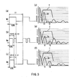
- Fig. 3 shows an inappropriate example, having a variable period deviating from that of the appropriate duty factor shown in Fig. 2 .
- Fig. 3 shows the case where the variable period t2 is set within the frequency band of the ultrasound generation means 1.
- Fig. 3 shows a relationship among a driving waveform generated by the waveform generation means 2, frequency spectrum thereof and frequency characteristics of the ultrasound generation means 1.
- W0, Wa and Wb represent driving waveforms generated by the waveform generation means 2, which show the examples of duty factors of 100%, 67% and 33%, respectively.
- Curves S0, Sa and Sb represent the frequency spectrum distribution corresponding to the waveforms W0, Wa and Wb, respectively.
- T represents the frequency characteristics of the ultrasound generation means 1.
- variable period t2 of the duty When the variable period t2 of the duty is set at a frequency within the frequency band of the ultrasound generation means 1, a harmonic component f2 appears within the frequency band of the ultrasound generation means 1, and even if the duty factor is decreased, driving due to the harmonic component f2 is carried out (the spectrum at f2 in Fig. 3(e) and (f) is increased). Thus, the effect of suppressing an acoustic power and heat generation cannot be obtained.
- an acoustic power of ultrasound transmitted from the ultrasound generation means can be controlled without varying the transmission amplitude, and an unnecessary increase of harmonics due to the change of duty factor can be suppressed. Therefore, an increase of the acoustic power and an increase of a surface temperature, which result from the transmission of unnecessary energy, can be suppressed as well.
- Fig. 4 is a block diagram showing one exemplary configuration of an ultrasound diagnostic device according to Embodiment 2 of the present invention.
- a duty factor of a driving waveform from a waveform generation means 2 is made variable so as to control an acoustic power, which is similar to Embodiment 1.
- a waveform control unit 4 in accordance with current mode information that is generated by a mode control unit 5, a waveform control unit 4 further determines a driving waveform, which is to be generated by the waveform generation means 2, so as to correspond to waveform information that is determined for each mode corresponding to the mode information at present.
- a peak of the amplitude should be increased with a reduced wave number.
- the Doppler (including two-dimensional Doppler) mode sensitivity is emphasized, and therefore the wave number should be increased.
- a power supply voltage may be made variable.
- acoustic pulses are transmitted at intervals of several tens ⁇ s, and in the case where plural modes operate concurrently, acoustic pulses for different modes should be transmitted alternatively or in order. As a result, the power supply voltage should be switched in a short time.
- the power supply voltage is not variable for each mode.
- the mode control unit 5 generates information concerning the mode of transmission at present, and the waveform control unit 4 holds a period t1, a period t2, a wave number and a duty factor corresponding to the mode. Therefore, the waveform information corresponding to the present mode is sent to the waveform generation means 2, so as to drive the ultrasound generation means 1.
- an acoustic power of ultrasound transmitted from the ultrasound generation means can be controlled without making a transmission amplitude variable for each mode, thus suppressing an increase in unnecessary second harmonics resulting from a change of duty factor.
- the driving amplitude of driving waveforms for the respective modes can be made uniform, whereby it is unnecessary to incorporate a plurality of and quick-response power supply units.
- Fig. 5 is a block diagram mainly showing an exemplary internal configuration of a waveform generation means 2 in an ultrasound diagnostic device according to Embodiment 3 of the present invention.
- the waveform generation means 2 shown in Fig. 5 may be applied to Embodiment 1 and Embodiment 2.
- Fig. 6 is a waveform chart of signals at the respective portions in Fig. 5 .
- the waveform generation means 2 is composed of a fundamental wave generation means 6, a modulated wave generation means 7, a multiplication means 8 and a driving means 9.
- the fundamental waveform generation means 6 and the modulated wave generation means 7 are triggered by a trigger waveform A, and the waveforms output from both means are in synchronization with each other.
- the fundamental waveform generation means 6 generates a driving waveform B that is for driving an ultrasound generation means 1, where the driving waveform B is determined by waveform information containing a period t1 and a wave number.
- the modulated wave generation means 7 outputs a waveform C whose duty factor has been controlled, and then the multiplication means 8 multiplies the waveform C by the waveform B, so as to make a duty factor of a waveform D variable.
- the waveform C is determined by a period t2 and a duty factor, and has a length including the entire time period of the waveform B (t3 ⁇ t4).
- the multiplication means 8 may be a circuit such as XOR circuit and AND circuit.
- the fundamental waveform generation means 6 in the present embodiment may be one included in a conventional ultrasound diagnostic device, which performs the deflection and convergence of ultrasound beams, as well as the generation of waveforms for driving the ultrasound generation means 1.
- Fig. 5 shows a complicated configuration in which the driving means 9 is included for driving the ultrasound generation means 1 at a high voltage
- the present embodiment can be implemented by simply adding the modulated wave generation means 7 and the multiplication means 8 to a conventional ultrasound diagnostic device.
- the multiplication means multiplies a single pulse or a burst pulse generated by the fundamental waveform generation means and a continuous rectangular wave with a variable duty factor that is generated by the modulated wave generation means.
- a driving waveform with a variable duty factor can be generated easily by simply adding a modulated wave generation means and a multiplication means to an existing fundamental waveform generation means without the use of a complicated logic circuit.
- Embodiments 1 to 3 exemplify and describe a unipoloar rectangular pulse waveform
- the present invention is not limited to this and is applicable to a bipolar rectangular pulse with positive and negative polarities as well.
- a small ultrasound diagnostic device can be provided at a low cost that enables the appropriate control by a single power supply unit so as to give a predetermined transmission power to a driving waveform different for each mode without excess or deficiency and without affecting properties of the driving waveform.
Landscapes
- Health & Medical Sciences (AREA)
- Life Sciences & Earth Sciences (AREA)
- Engineering & Computer Science (AREA)
- Biomedical Technology (AREA)
- Medical Informatics (AREA)
- Pathology (AREA)
- Radiology & Medical Imaging (AREA)
- Biophysics (AREA)
- Physics & Mathematics (AREA)
- Heart & Thoracic Surgery (AREA)
- Nuclear Medicine, Radiotherapy & Molecular Imaging (AREA)
- Molecular Biology (AREA)
- Surgery (AREA)
- Animal Behavior & Ethology (AREA)
- General Health & Medical Sciences (AREA)
- Public Health (AREA)
- Veterinary Medicine (AREA)
- Mechanical Engineering (AREA)
- Ultra Sonic Daignosis Equipment (AREA)
Claims (2)
- Ultraschalldiagnosevorrichtung, umfassend:ein Ultraschallerzeugungsmittel (1), welches Ultraschall aussendet;ein Wellenformerzeugungsmittel (2), welches einen Einzelimpuls oder einen Burst-Impuls erzeugt, dessen Tastverhältnis variabel ist, um das Ultraschallerzeugungsmittel (1) anzusteuern,eine Energieversorgungseinheit (3), welche eine Amplitude einer Ansteuerwellenform bestimmt, die von dem Wellenformerzeugungsmittel (2) erzeugt wird; undein Multiplikationsmittel (8), welches eine erste Wellenform mit einer zweiten Wellenform multipliziert, um das Tastverhältnis der Ansteuerwellenform für das Ultraschallerzeugungsmittel (1) einzustellen,dadurch gekennzeichnet, dass das Wellenformerzeugungsmittel (2) umfasst:ein Grundwellenform-Erzeugungsmittel (6), welches den Einzelimpuls oder den Burst-Impuls als die erste Wellenform erzeugt; und ein Erzeugungsmittel für eine modulierte Welle (7), welches eine kontinuierliche Rechteckwelle als die zweite Wellenform erzeugt, deren Tastverhältnis variabel während eines Zeitabschnitts ist, in welchem das Grundwellenform-Erzeugungsmittel (6) Impulse erzeugt, wobei das Tastverhältnis variabel in Einheiten einer Zeit ist, welche eine Zeitdauer ist, die einer Frequenz außerhalb eines Frequenzbandes des Ultraschallerzeugungsmittels (1) entspricht, um das Ultraschallerzeugungsmittel (1) anzusteuern.
- Ultraschalldiagnosevorrichtung gemäß Anspruch 1, umfassend eine Moden-Steuereinheit (5), welche Moden-Informationen für jede Übertragung erzeugt; und eine Wellenform-Steuereinheit (4), welche eine Impulsbreite, eine Wellenzahl und ein Tastverhältnis einer Ansteuerwellenform, die von dem Wellenformerzeugungsmittel (2) erzeugt wird, auf der Basis der Moden-Informationen von der Moden-Steuereinheit (5) einstellt.
Applications Claiming Priority (2)
| Application Number | Priority Date | Filing Date | Title |
|---|---|---|---|
| JP2003166803 | 2003-06-11 | ||
| PCT/JP2004/008483 WO2004110278A1 (ja) | 2003-06-11 | 2004-06-10 | 超音波診断装置 |
Publications (3)
| Publication Number | Publication Date |
|---|---|
| EP1632183A1 EP1632183A1 (de) | 2006-03-08 |
| EP1632183A4 EP1632183A4 (de) | 2008-11-05 |
| EP1632183B1 true EP1632183B1 (de) | 2011-01-19 |
Family
ID=33549269
Family Applications (1)
| Application Number | Title | Priority Date | Filing Date |
|---|---|---|---|
| EP04746011A Expired - Lifetime EP1632183B1 (de) | 2003-06-11 | 2004-06-10 | Ultraschallgerät |
Country Status (6)
| Country | Link |
|---|---|
| US (1) | US7566304B2 (de) |
| EP (1) | EP1632183B1 (de) |
| JP (1) | JP4575880B2 (de) |
| CN (1) | CN100496405C (de) |
| DE (1) | DE602004031107D1 (de) |
| WO (1) | WO2004110278A1 (de) |
Families Citing this family (15)
| Publication number | Priority date | Publication date | Assignee | Title |
|---|---|---|---|---|
| WO2008132835A1 (ja) * | 2007-04-24 | 2008-11-06 | Panasonic Corporation | 超音波診断装置 |
| US20100256498A1 (en) * | 2007-11-16 | 2010-10-07 | Hiroki Tanaka | Ultrasonic imaging device |
| JP5384491B2 (ja) * | 2008-06-05 | 2014-01-08 | 株式会社日立メディコ | 超音波診断装置 |
| JP4627556B2 (ja) * | 2008-08-08 | 2011-02-09 | アロカ株式会社 | 超音波診断装置 |
| JP5783807B2 (ja) * | 2011-06-01 | 2015-09-24 | 株式会社東芝 | 超音波診断装置及びその制御プログラム |
| CN104169739B (zh) | 2011-10-28 | 2017-04-12 | 决策科学国际公司 | 超声成像中的扩频编码波形 |
| US9844359B2 (en) | 2013-09-13 | 2017-12-19 | Decision Sciences Medical Company, LLC | Coherent spread-spectrum coded waveforms in synthetic aperture image formation |
| US10743838B2 (en) | 2015-02-25 | 2020-08-18 | Decision Sciences Medical Company, LLC | Acoustic signal transmission couplants and coupling mediums |
| CA3001315C (en) | 2015-10-08 | 2023-12-19 | Decision Sciences Medical Company, LLC | Acoustic orthopedic tracking system and methods |
| JP6852603B2 (ja) * | 2017-07-10 | 2021-03-31 | コニカミノルタ株式会社 | 超音波診断装置、送信条件設定方法、およびプログラム |
| US12017389B2 (en) | 2019-03-06 | 2024-06-25 | Decision Sciences Medical Company, LLC | Methods for manufacturing and distributing semi-rigid acoustic coupling articles and packaging for ultrasound imaging |
| US11154274B2 (en) | 2019-04-23 | 2021-10-26 | Decision Sciences Medical Company, LLC | Semi-rigid acoustic coupling articles for ultrasound diagnostic and treatment applications |
| JP2023549818A (ja) | 2020-11-13 | 2023-11-29 | ディスィジョン サイエンシズ メディカル カンパニー,エルエルシー | 物体の合成開口超音波撮像のためのシステムおよび方法 |
| CN113030882B (zh) * | 2020-12-30 | 2024-01-09 | 南京理工大学 | 一种无载波超宽带发射信号波形库的构建方法 |
| JP2023173610A (ja) * | 2022-05-26 | 2023-12-07 | コニカミノルタ株式会社 | 超音波診断装置、駆動信号生成方法、およびプログラム |
Family Cites Families (13)
| Publication number | Priority date | Publication date | Assignee | Title |
|---|---|---|---|---|
| US4596951A (en) * | 1984-03-19 | 1986-06-24 | Westinghouse Electric Corp. | Electronic circuit for measuring AC electrical energy |
| US4910456A (en) * | 1988-12-22 | 1990-03-20 | Asea Brown Boveri Inc. | Electronic watt-hour meter with combined multiplier/integrator circuit |
| JPH03262466A (ja) | 1990-03-12 | 1991-11-22 | Niitoretsukusu Honsha:Kk | アロエ及びニンニク入り飲料水 |
| JPH03261466A (ja) * | 1990-03-12 | 1991-11-21 | Toshiba Corp | 超音波診断装置 |
| US5509413A (en) | 1993-08-11 | 1996-04-23 | Kabushiki Kaisha Toshiba | Ultrasonic diagnostic apparatus |
| JP3378308B2 (ja) * | 1993-09-02 | 2003-02-17 | 株式会社東芝 | 超音波診断装置 |
| JP3007782B2 (ja) * | 1993-12-07 | 2000-02-07 | フクダ電子株式会社 | 超音波診断装置 |
| JPH07155324A (ja) * | 1993-12-09 | 1995-06-20 | Matsushita Electric Ind Co Ltd | 超音波診断装置 |
| US5694937A (en) | 1995-01-31 | 1997-12-09 | Kabushiki Kaisha Toshiba | Ultrasound diagnostic apparatus and method |
| JP3023290B2 (ja) | 1995-04-14 | 2000-03-21 | 株式会社東芝 | 超音波診断装置 |
| JP3500099B2 (ja) | 1999-09-28 | 2004-02-23 | アロカ株式会社 | 超音波診断装置の送信回路 |
| US6432055B1 (en) * | 2000-06-30 | 2002-08-13 | Acuson Corporation | Medical ultrasonic imaging system with three-state ultrasonic pulse and improved pulse generator |
| US6669638B1 (en) * | 2002-10-10 | 2003-12-30 | Koninklijke Philips Electronics N.V. | Imaging ultrasound transducer temperature control system and method |
-
2004
- 2004-06-10 EP EP04746011A patent/EP1632183B1/de not_active Expired - Lifetime
- 2004-06-10 US US10/556,277 patent/US7566304B2/en not_active Expired - Fee Related
- 2004-06-10 DE DE602004031107T patent/DE602004031107D1/de not_active Expired - Lifetime
- 2004-06-10 WO PCT/JP2004/008483 patent/WO2004110278A1/ja not_active Ceased
- 2004-06-10 CN CNB2004800163889A patent/CN100496405C/zh not_active Expired - Fee Related
- 2004-06-10 JP JP2005506992A patent/JP4575880B2/ja not_active Expired - Fee Related
Also Published As
| Publication number | Publication date |
|---|---|
| DE602004031107D1 (de) | 2011-03-03 |
| WO2004110278A1 (ja) | 2004-12-23 |
| CN1805709A (zh) | 2006-07-19 |
| EP1632183A1 (de) | 2006-03-08 |
| JP4575880B2 (ja) | 2010-11-04 |
| EP1632183A4 (de) | 2008-11-05 |
| CN100496405C (zh) | 2009-06-10 |
| US7566304B2 (en) | 2009-07-28 |
| US20070010744A1 (en) | 2007-01-11 |
| JPWO2004110278A1 (ja) | 2006-07-27 |
Similar Documents
| Publication | Publication Date | Title |
|---|---|---|
| EP1632183B1 (de) | Ultraschallgerät | |
| US20130310689A1 (en) | Ultrasound diagnostic device | |
| US10468009B2 (en) | Ultrasound generation | |
| US8147409B2 (en) | Method and apparatus for transducer excitation in medical ultrasound imaging | |
| Smith et al. | Width-modulated square-wave pulses for ultrasound applications | |
| US6960169B2 (en) | Spread spectrum coding for ultrasound contrast agent imaging | |
| GB2402484A (en) | Driving signals for ultrasonic scanning sonar transmitter | |
| CN102056546B (zh) | 超声波诊断装置 | |
| JP2007503242A (ja) | マイクロビームフォーマのための送信アポダイゼイション制御 | |
| NL8000562A (nl) | Ultrasone medisch-diagnostische inrichting en werkwijze. | |
| US9581685B2 (en) | Ultrasonic diagnostic apparatus with pulse timing controller | |
| KR100947829B1 (ko) | 초음파 진단 시스템에서 펄스폭 변조된 송신 펄스를생성하는 송신 펄스 생성 장치 | |
| JP3897991B2 (ja) | 超音波診断装置用送信回路 | |
| WO1989005122A1 (fr) | Appareil diagnostique ultrasonique | |
| JPH05130992A (ja) | ドプラ超音波診断装置の電源装置 | |
| JP3286311B2 (ja) | 超音波診断装置 | |
| JP2007244638A (ja) | 超音波診断装置 | |
| JP2005211334A (ja) | 超音波診断装置 | |
| JP3241704B2 (ja) | 超音波診断装置 | |
| US20240288578A1 (en) | Method and system for controlling a wave-transmitting device | |
| JP2005110934A (ja) | 超音波診断装置 | |
| US20240109101A1 (en) | Method for driving a transmitting device | |
| JP2001137777A (ja) | 超音波送信信号発生回路及び超音波診断装置 | |
| JP2025110771A (ja) | 超音波診断装置、駆動信号生成方法および駆動信号生成プログラム | |
| JPH03261463A (ja) | 超音波診断装置 |
Legal Events
| Date | Code | Title | Description |
|---|---|---|---|
| PUAI | Public reference made under article 153(3) epc to a published international application that has entered the european phase |
Free format text: ORIGINAL CODE: 0009012 |
|
| 17P | Request for examination filed |
Effective date: 20051103 |
|
| AK | Designated contracting states |
Kind code of ref document: A1 Designated state(s): DE FR GB |
|
| DAX | Request for extension of the european patent (deleted) | ||
| RBV | Designated contracting states (corrected) |
Designated state(s): DE FR GB |
|
| A4 | Supplementary search report drawn up and despatched |
Effective date: 20081002 |
|
| RAP1 | Party data changed (applicant data changed or rights of an application transferred) |
Owner name: PANASONIC CORPORATION |
|
| 17Q | First examination report despatched |
Effective date: 20081218 |
|
| GRAP | Despatch of communication of intention to grant a patent |
Free format text: ORIGINAL CODE: EPIDOSNIGR1 |
|
| GRAS | Grant fee paid |
Free format text: ORIGINAL CODE: EPIDOSNIGR3 |
|
| GRAA | (expected) grant |
Free format text: ORIGINAL CODE: 0009210 |
|
| AK | Designated contracting states |
Kind code of ref document: B1 Designated state(s): DE FR GB |
|
| REG | Reference to a national code |
Ref country code: GB Ref legal event code: FG4D |
|
| REF | Corresponds to: |
Ref document number: 602004031107 Country of ref document: DE Date of ref document: 20110303 Kind code of ref document: P |
|
| REG | Reference to a national code |
Ref country code: DE Ref legal event code: R096 Ref document number: 602004031107 Country of ref document: DE Effective date: 20110303 |
|
| PLBE | No opposition filed within time limit |
Free format text: ORIGINAL CODE: 0009261 |
|
| STAA | Information on the status of an ep patent application or granted ep patent |
Free format text: STATUS: NO OPPOSITION FILED WITHIN TIME LIMIT |
|
| 26N | No opposition filed |
Effective date: 20111020 |
|
| REG | Reference to a national code |
Ref country code: DE Ref legal event code: R097 Ref document number: 602004031107 Country of ref document: DE Effective date: 20111020 |
|
| REG | Reference to a national code |
Ref country code: DE Ref legal event code: R082 Ref document number: 602004031107 Country of ref document: DE Representative=s name: PATENTANWAELTE HENKEL, BREUER & PARTNER, DE |
|
| REG | Reference to a national code |
Ref country code: DE Ref legal event code: R082 Ref document number: 602004031107 Country of ref document: DE Representative=s name: PATENTANWAELTE HENKEL, BREUER & PARTNER, DE |
|
| REG | Reference to a national code |
Ref country code: GB Ref legal event code: 732E Free format text: REGISTERED BETWEEN 20140417 AND 20140423 |
|
| REG | Reference to a national code |
Ref country code: FR Ref legal event code: TP Owner name: KONICA MINOLTA, INC., JP Effective date: 20140428 |
|
| REG | Reference to a national code |
Ref country code: DE Ref legal event code: R082 Ref document number: 602004031107 Country of ref document: DE Representative=s name: PATENTANWAELTE HENKEL, BREUER & PARTNER, DE Effective date: 20140506 Ref country code: DE Ref legal event code: R082 Ref document number: 602004031107 Country of ref document: DE Representative=s name: PATENTANWAELTE HENKEL, BREUER & PARTNER, DE Effective date: 20140225 Ref country code: DE Ref legal event code: R081 Ref document number: 602004031107 Country of ref document: DE Owner name: KONICA MINOLTA, INC., JP Free format text: FORMER OWNER: PANASONIC CORPORATION, KADOMA, JP Effective date: 20140506 Ref country code: DE Ref legal event code: R081 Ref document number: 602004031107 Country of ref document: DE Owner name: KONICA MINOLTA, INC., JP Free format text: FORMER OWNER: PANASONIC CORPORATION, KADOMA, OSAKA, JP Effective date: 20140506 Ref country code: DE Ref legal event code: R082 Ref document number: 602004031107 Country of ref document: DE Representative=s name: PATENTANWAELTE HENKEL, BREUER & PARTNER MBB, DE Effective date: 20140506 Ref country code: DE Ref legal event code: R082 Ref document number: 602004031107 Country of ref document: DE Representative=s name: PATENTANWAELTE HENKEL, BREUER & PARTNER MBB, DE Effective date: 20140225 |
|
| PGFP | Annual fee paid to national office [announced via postgrant information from national office to epo] |
Ref country code: GB Payment date: 20140604 Year of fee payment: 11 |
|
| PGFP | Annual fee paid to national office [announced via postgrant information from national office to epo] |
Ref country code: FR Payment date: 20140609 Year of fee payment: 11 |
|
| GBPC | Gb: european patent ceased through non-payment of renewal fee |
Effective date: 20150610 |
|
| REG | Reference to a national code |
Ref country code: FR Ref legal event code: ST Effective date: 20160229 |
|
| PG25 | Lapsed in a contracting state [announced via postgrant information from national office to epo] |
Ref country code: GB Free format text: LAPSE BECAUSE OF NON-PAYMENT OF DUE FEES Effective date: 20150610 |
|
| PG25 | Lapsed in a contracting state [announced via postgrant information from national office to epo] |
Ref country code: FR Free format text: LAPSE BECAUSE OF NON-PAYMENT OF DUE FEES Effective date: 20150630 |
|
| PGFP | Annual fee paid to national office [announced via postgrant information from national office to epo] |
Ref country code: DE Payment date: 20180530 Year of fee payment: 15 |
|
| REG | Reference to a national code |
Ref country code: DE Ref legal event code: R119 Ref document number: 602004031107 Country of ref document: DE |
|
| PG25 | Lapsed in a contracting state [announced via postgrant information from national office to epo] |
Ref country code: DE Free format text: LAPSE BECAUSE OF NON-PAYMENT OF DUE FEES Effective date: 20200101 |