EP1632307B1 - Méthode et appareil pour soudage par recouvrement de tôles tubulaires - Google Patents
Méthode et appareil pour soudage par recouvrement de tôles tubulaires Download PDFInfo
- Publication number
- EP1632307B1 EP1632307B1 EP05017733A EP05017733A EP1632307B1 EP 1632307 B1 EP1632307 B1 EP 1632307B1 EP 05017733 A EP05017733 A EP 05017733A EP 05017733 A EP05017733 A EP 05017733A EP 1632307 B1 EP1632307 B1 EP 1632307B1
- Authority
- EP
- European Patent Office
- Prior art keywords
- sheet metal
- metal body
- casing tool
- tool
- rail
- Prior art date
- Legal status (The legal status is an assumption and is not a legal conclusion. Google has not performed a legal analysis and makes no representation as to the accuracy of the status listed.)
- Expired - Lifetime
Links
Images
Classifications
-
- B—PERFORMING OPERATIONS; TRANSPORTING
- B23—MACHINE TOOLS; METAL-WORKING NOT OTHERWISE PROVIDED FOR
- B23K—SOLDERING OR UNSOLDERING; WELDING; CLADDING OR PLATING BY SOLDERING OR WELDING; CUTTING BY APPLYING HEAT LOCALLY, e.g. FLAME CUTTING; WORKING BY LASER BEAM
- B23K11/00—Resistance welding; Severing by resistance heating
- B23K11/08—Seam welding not restricted to one of the preceding subgroups
- B23K11/087—Seam welding not restricted to one of the preceding subgroups for rectilinear seams
- B23K11/0873—Seam welding not restricted to one of the preceding subgroups for rectilinear seams of the longitudinal seam of tubes
-
- B—PERFORMING OPERATIONS; TRANSPORTING
- B23—MACHINE TOOLS; METAL-WORKING NOT OTHERWISE PROVIDED FOR
- B23K—SOLDERING OR UNSOLDERING; WELDING; CLADDING OR PLATING BY SOLDERING OR WELDING; CUTTING BY APPLYING HEAT LOCALLY, e.g. FLAME CUTTING; WORKING BY LASER BEAM
- B23K11/00—Resistance welding; Severing by resistance heating
- B23K11/06—Resistance welding; Severing by resistance heating using roller electrodes
- B23K11/061—Resistance welding; Severing by resistance heating using roller electrodes for welding rectilinear seams
- B23K11/062—Resistance welding; Severing by resistance heating using roller electrodes for welding rectilinear seams for welding longitudinal seams of tubes
- B23K11/063—Lap welding
-
- B—PERFORMING OPERATIONS; TRANSPORTING
- B23—MACHINE TOOLS; METAL-WORKING NOT OTHERWISE PROVIDED FOR
- B23K—SOLDERING OR UNSOLDERING; WELDING; CLADDING OR PLATING BY SOLDERING OR WELDING; CUTTING BY APPLYING HEAT LOCALLY, e.g. FLAME CUTTING; WORKING BY LASER BEAM
- B23K37/00—Auxiliary devices or processes, not specially adapted for a procedure covered by only one of the other main groups of this subclass
- B23K37/04—Auxiliary devices or processes, not specially adapted for a procedure covered by only one of the other main groups of this subclass for holding or positioning work
- B23K37/053—Auxiliary devices or processes, not specially adapted for a procedure covered by only one of the other main groups of this subclass for holding or positioning work aligning cylindrical work; Clamping devices therefor
- B23K37/0535—Longitudinal pipe seam alignment clamps
-
- B—PERFORMING OPERATIONS; TRANSPORTING
- B23—MACHINE TOOLS; METAL-WORKING NOT OTHERWISE PROVIDED FOR
- B23K—SOLDERING OR UNSOLDERING; WELDING; CLADDING OR PLATING BY SOLDERING OR WELDING; CUTTING BY APPLYING HEAT LOCALLY, e.g. FLAME CUTTING; WORKING BY LASER BEAM
- B23K2101/00—Articles made by soldering, welding or cutting
- B23K2101/04—Tubular or hollow articles
- B23K2101/12—Vessels
- B23K2101/125—Cans
Definitions
- the invention relates to a method and a device for lap welding of tubular sheet metal bodies, in particular Be fiscallyzargen according to the preambles of claims 1 and 10.
- a method and such a device are made of US-A-4 525 617 known.
- Tubular hollow bodies in particular container frames, can be welded in small series on semi-automatic welding machines with an overlapping longitudinal seam.
- a resistance welding with welding rollers and supply of a wire-shaped electrode takes place.
- Z-rail which specifies the overlap.
- From the Z-rail of the sheet metal body is conveyed into the welding area to weld the corresponding overlapping longitudinal edges.
- a guide and clamping device according DE-A-103 13 298 known.
- a small overlap width of 1-2 mm even in semi-automatic welding machines, in which the welding material is handled by an operator to be achieved. This is to avoid a so-called butterfly seam with protruding from the frame body edges.
- EP-A-0 701 878 it is known in butt welding of pipes, bring this from above into an adjustable strap and position with it.
- US-A-4 525 617 For example, a method and an apparatus for seam welding a tubular sheet metal body are described. The longitudinal edges of the sheet metal body are introduced into a Z-rail and are guided along it. The sheet metal body is held by a holding tool, which comprises concave contact plates or contact rollers.
- the invention is based on the object of overlap welding on semi-automatic welding machines, the overlapping area reproducible and easily with a small width, of e.g. 0.8-1.5 mm, and to allow easy handling.
- a sheath tool which the sheet metal body to be welded practically completely, i. from near the one Z-rail side to near the other Z-rail side, and this by a preformed, i. according to the shape and the diameter of the body to be welded preformed adapted, an openable and closable jacket performs around the body forming tool, on the one hand a precise and uniform pressing on the Z-rail is achieved, on the other hand, even thin-walled body of the desired tube shape can perform deviant deformation outside the Z-rail.
- the overlapping area can be precisely maintained and thus kept very small.
- a simple jacket tool is preferably created from a thin sheet metal blank, which ensures the scratch-free guidance and positioning of the weld material and also allows easy loading of the welding machine.
- the sheath tool is to the maximum welding length of the lap welding machine coordinated, so that a sheet metal body with the maximum possible welding length can be completely absorbed (from end to end) in the shell tool.
- the sheath tool is further designed so that it acts not only from near the Z-rail on the sheet body, but even in the Z-rail itself, including the sheath tool is provided with projections preferably with strips at its longitudinal edges, which up in extend the Z-rail.
- the sheath tool has at least one end stop to allow a defined introduction of the sheet metal body in the open sheath tool to the end stop.
- At least two end stops are provided for this, wherein these are arranged on both sides of the vertical central longitudinal plane of the shell tool in order to achieve a uniform end position of the sheet metal body in the shell tool.
- at least one further adjustable stop is provided in order to be able to bring in shorter and also very short hollow bodies (rings) with a defined end stop.
- the setting of such other attacks can be done in stages or continuously.
- a preferred cladding tool is formed from a single, pre-bent and corresponding to the sheet metal body sized sheet metal blank, which is optionally still provided with the mentioned projections or strips for engagement in the Z-rail. This jacket tool can be spread due to its elasticity by any actuation elements for opening and brought to close in its predetermined round shape.
- a further preferred jacket tool is formed from two preformed half-shells, which are connected to one another by means of a connecting piece, which is generally diametrically opposed to the welding zone.
- a jacket tool can be opened and closed by the elasticity of the two half-shells.
- the at least one preferred adjustable stop can be arranged on the connecting piece be.
- the jacket tool is provided at the insertion opening or end face on its underside with at least one projection which forms a storage area for the sheet metal body and thus substantially facilitates the manual loading of the jacket tool.
- at least one recess is arranged in the sheath tool at the insertion opening and preferably two recesses are arranged on both sides of the vertical center plane of the tool in order to facilitate the loading by holding the sheet metal body by hand "inside" the sheath tool.
- the jacket tool can be used with appropriate cutting and preforming for non-round in cross-section and also for conical sheet metal body.
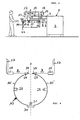
- FIG. 1 shows in a crude schematic manner, a semi-automatic welding machine for generating lap welds, which in particular for Welding the longitudinal seams of tubular sheet metal bodies, in particular Gebindezargen is used.
- the semi-automatic welding machine can be, for example, a resistance seam welding machine of the type AFB 002 from Soudronic, Bergdietikon, Switzerland.
- the present invention can be used in any welding machines with a Z-rail for generating the overlapping weld.
- the welding machine 1 is shown only schematically with its machine frame 2, on which the lower arm 3 of the welding machine with the lower welding roller 6 is arranged. Also on the machine frame, the upper welding arm 4 is arranged with the upper welding roller 7.
- the wire guide and the wire supply for the commonly used wire electrode which runs on the welding rollers. This is known from the commercially available welding machines ago and need not be explained here. Also well known to those skilled in the art is to use a so-called Z-bar 5 to effect the overlap of the longitudinal edges of the sheet metal body to be welded.
- the Z-rail 5 is therefore indicated here only schematically. It ends in the direction of welding, which is the direction of the operator shown, just before the welding rollers, where the longitudinal edges must have taken the defined overlap.
- a sheath die 10 is now used to weld the tubular sheet metal body 11 to be welded, which is in FIG. 1 indicated in broken line as lying in the shell tool 10 hollow body to load in the welding machine and the welding position to supply.
- FIG. 1 shows a position of the shell tool 10, in which already about half of the sheet metal body 11 is welded.
- the casing tool 10 is arranged on a movable carriage 12, which is movable both in the direction of welding and counter to the direction of welding, which is indicated by the arrow A is hinted at.
- the carriage 12 is arranged movably on the machine frame 2, which is to be indicated only schematically by the rollers 18.
- a drive 17 for the carriage is an arbitrary motor drive, which is synchronized with the drive of the welding rollers 6, 7 or the wire electrode so that preferably the advance of the carriage 12 in the direction of welding is the same speed as the welding speed.
- the aforementioned sheath tool 10 is attached via only indicated fasteners, so that it is moved together with the car.
- the casing tool 10 can be opened and closed again by any movement means 15 and 16, as will be explained.
- the sheath tool is moved forward (towards the operator or in the direction of welding) and the welding machine 1 is driven to weld.
- the casing tool 10 forms in closed form a gap between its longitudinal edges, in which the welding rollers can perform the welding in a known manner and weld the longitudinal edges of the sheet metal body brought into overlap by the Z-rail.
- the sheet metal body itself is frictionally guided by the casing tool, on the inner surface of the sheet metal body, or optionally additionally guided by the end stops by the welding rollers. If the welding is completed by the entire longitudinal seam of the sheet metal body is finished welded, so the jacket tool is in front of the welding rollers in the operator and can be opened so that the operator can remove the welded sheet metal body.
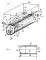
- FIG. 2 shows a schematic perspective view of the sheath tool 10, which is attached to the only indicated carriage 12 with the fasteners 13, 14 and which can be opened and closed with the actuators 15, 16.
- the opening and closing of the casing tool means that its longitudinal edges, which are shown in the drawing as rod-shaped end portions 24 and 25, can be moved away from each other to open the tool and moved toward each other to close the tool.
- the closed tool is with its longitudinal edges 24, 25 adjacent to the Z-rail 8, which indicated only greatly simplified in the drawing is.
- the shell mold 10 is adapted in shape and in size to the sheet metal body to be welded, so that it is fully encompassed in the closed shell tool substantially (apart from the Z-rail), so that the sheet metal body to be welded around supported by the shell tool and is held.
- the sheet metal body 11 to be welded is visible in the closed jacket tool, which further has the mentioned projection 22 and the recesses 20 and 21. Furthermore, the end stops 28 are indicated in the figure. Likewise, the welding rollers 6 and 7 and the upper welding wire 9 are partially visible.
- the actuators 15 and 16 which may be any actuators that can perform a movement corresponding to the arrows B to move the shell tool by a Auffactzu its longitudinal edges 24, 25 to close or move by a Vonchroweg this longitudinal edges to open .
- the jacket tool 10 which is preferably made from a sheet metal blank, is sufficiently elastic in this case to permit this movement without further ado.
- FIG. 3 shows a corresponding development of the sheath tool 10, wherein like reference numerals designate the aforementioned parts.
- FIG. 4 to explain further preferred features, a view of the sheath tool from the front or its front side.
- the jacket tool can have projections 34, 35 adjoining its longitudinal edges 24, 25, which can likewise extend over the entire longitudinal extent of the jacket tool or with interruptions only over a part of the same, and which projections, for example, are strip-shaped and may at most consist of a different material than the casing tool itself.
- These projections 34 and 35 preferably engage a distance, for example a few tenths of a millimeter into the Z-rail and cause a better positioning of the sheet metal body to be welded or of its longitudinal edges in the Z-rail.
- the sheath tool could be designed so that its longitudinal edges 24 and 25 are designed directly so that they can reach into the Z-rail accordingly. In the embodiment shown, however, the longitudinal edges 24, 25 are in turn designed rod-like and enlarged in order to form the engagement region for the actuating elements 15 (or lying further back and therefore not visible in the figure 16).
- the described embodiment of the longitudinal edges with the projections may be formed with the one-piece shell tool of Figures 2 and 3.
- FIG. 4 shows a further embodiment of the sheath tool, wherein these two half-shells 10 ', which are interconnected by a connecting means 30. This is preferably in the vertical center plane V of the sheath tool 10 and consists for example of a strip of plastic or other material.
- the two half shells 10 'made of sheet metal allow by their elasticity in turn the opening and closing of the sheath tool 10th
- the casing tool 10 is as mentioned from a sheet metal blank.
- the sheet is completely closed, so that the sheet metal body 11 to be welded is supported uniformly around and can rest against the shell tool, whereby the risk of deformations of the sheet metal body 11, which could interfere with the positioning and overlapping by the Z-rail, completely eliminated.
- the tool could also have on its lateral surface some recesses and so. be configured grid-shaped or reticulated. In any case, it is important that the substantially complete enclosure of the sheet metal body 11, so that said risk of deformation does not exist.
Landscapes
- Engineering & Computer Science (AREA)
- Mechanical Engineering (AREA)
- Physics & Mathematics (AREA)
- Optics & Photonics (AREA)
- Butt Welding And Welding Of Specific Article (AREA)
- Making Paper Articles (AREA)
- Lining Or Joining Of Plastics Or The Like (AREA)
- Laminated Bodies (AREA)
Claims (18)
- Procédé permettant le soudage par recouvrement de corps en tôle (11) précourbés sous forme tubulaire, en particulier des corps de récipients, dans lequel un corps en tôle (11) est amené à faire l'objet d'un recouvrement défini avec ses bords longitudinaux opposés dans la zone de soudage à l'aide d'un rail en Z (5) et soudé à cet endroit, caractérisé en ce que le corps en tôle, lorsqu'il est introduit dans la machine à souder (2), est introduit dans un outil d'enveloppement (10) ouvert, adapté de manière préformée à la forme du tube en partant de sa face frontale, sachant que l'outil d'enveloppement est un corps creux pouvant être déformé de manière élastique par un dispositif d'ouverture et de fermeture (13 à 16), qui est positionné le long du rail en Z, de telle sorte que les bords longitudinaux du corps en tôle peuvent être introduits dans le rail en Z lors de l'introduction dans l'outil d'enveloppement, de telle sorte que l'outil d'enveloppement se ferme afin d'envelopper le corps en tôle, hormis la zone du rail en Z, et d'appuyer les bords longitudinaux du corps en tôle sur le rail en Z, et en ce que l'outil d'enveloppement est amené à se déplacer dans le sens de soudage avec le corps en tôle qui se trouve à l'intérieur afin de souder le corps en tôle entouré par l'outil d'enveloppement, et en ce que, une fois que l'opération de soudage est terminée, l'outil d'enveloppement est ouvert par le dispositif d'ouverture et de fermeture, et le corps en tôle est extrait.
- Dispositif selon la revendication 1, caractérisé en ce que la longueur de l'outil d'enveloppement est supérieure à la longueur du corps en tôle à souder.
- Procédé selon la revendication 1 ou 2, caractérisé en ce que l'outil d'enveloppement entoure le corps en tôle le long de toute sa paroi, hormis une zone dans ou à proximité du rail en Z.
- Procédé selon la revendication 3, caractérisé en ce que l'outil d'enveloppement va jusqu'au rail en Z lors de la fermeture.
- Procédé selon l'une quelconque des revendications 1 à 4, caractérisé en ce que l'outil d'enveloppement est formé par une section de tôle recourbée de manière tubulaire individuelle, ou en ce que l'outil d'enveloppement est constitué de deux demi-coques (10') reliées par un moyen de raccordement, et le cas échéant dotées de saillies (34, 35) allant respectivement jusqu'au rail en Z, se présentant en particulier sous la forme de nervures périphériques.
- Procédé selon l'une quelconque des revendications 1 à 5, caractérisé en ce que l'outil d'enveloppement est doté d'au moins une butée d'extrémité (28) faisant saillie dans son espace interne, et présente de préférence deux butées d'extrémité se trouvant des deux côtés du plan vertical médian, contre lesquelles le corps en tôle est poussé lors de l'introduction dans l'outil d'enveloppement.
- Procédé selon l'une quelconque des revendications 1 à 6, caractérisé en ce qu'on prévoit au moins une butée d'extrémité (31), contre laquelle le corps en tôle est poussé lors de l'introduction dans l'outil d'enveloppement, laquelle butée d'extrémité peut être réglée en termes de positionnement dans le sens de soudage et/ou sachant que plusieurs butées d'extrémité se trouvant l'une derrière l'autre dans le sens de soudage sont prévues, lesquelles peuvent être positionnées au choix en faisant saillie dans l'espace interne.
- Procédé selon l'une quelconque des revendications 1 à 7, caractérisé en ce que l'outil d'enveloppement présente, sur sa face inférieure, au moins une saillie (22) dépassant dans le sens de soudage, sur laquelle est déposé le corps en tôle à souder lors de l'introduction dans l'outil d'enveloppement.
- Procédé selon l'une quelconque des revendications 1 à 8, caractérisé en ce que l'outil d'enveloppement présente des évidements (20, 21), du côté frontal, des deux côtés de son plan médian vertical (V), grâce auxquels l'introduction complète du corps en tôle à l'encontre du sens de soudage dans l'outil d'enveloppement est simplifiée.
- Dispositif permettant le soudage par recouvrement de corps en tôle (11) précourbés tubulaires, en particulier des corps de récipients, comportant :un rail en Z (5), grâce auquel un corps en tôle (11) est amené à faire l'objet d'un recouvrement défini avec ses bords longitudinaux opposés dans la zone de soudage à l'aide d'un rail en Z (5) et peut être soudé à cet endroit,;un outil d'enveloppement (10), qui peut être déplacé avec le corps en tôle (11) se trouvant à l'intérieur dans le sens de soudage, afin de souder le corps en tôle (11) entouré par l'outil d'enveloppement (10), sachant que le corps en tôle (11) peut être introduit dans l'outil d'enveloppement (10) ouvert à partir de sa face frontale pour parvenir dans le dispositif ;un dispositif de fermeture (13 à 16) permettant de fermer l'outil d'enveloppement (10), caractérisé en ce que :l'outil d'enveloppement (10) est un corps creux pouvant être adapté en étant préformé à la forme du tube, qui peut être déformé de manière élastique par un dispositif d'ouverture et de fermeture (13 à 16), lequel corps creux peut être positionné le long du rail en Z (5), de telle sorte que les bords longitudinaux du corps en tôle (11) peuvent être introduits dans le rail en Z (5) lors de l'insertion dans l'outil d'enveloppement (10), eten ce que l'outil d'enveloppement (10) peut être fermé afin d'envelopper le corps en tôle (11), hormis la zone de rail en Z (5), et d'appuyer les bords longitudinaux du corps en tôle (11) sur le rail en Z (5).
- Dispositif selon la revendication 10, caractérisé en ce que la longueur de l'outil d'enveloppement est supérieure à la longueur de corps en tôle à souder.
- Dispositif selon la revendication 10 ou 11, caractérisé en ce que l'outil d'enveloppement entoure le corps en tôle le long de toute sa paroi, hormis la zone de ou à proximité du rail en Z.
- Dispositif selon la revendication 12, caractérisé en ce que l'outil d'enveloppement va jusqu'au rail en Z lors de la fermeture.
- Dispositif selon l'une quelconque des revendications 10 à 13, caractérisé en ce que l'outil d'enveloppement (10) est formé par une section de tôle incurvée tubulaire unique, ou en ce que l'outil d'enveloppement est constitué de deux demi-coques (10') reliées par un moyen de raccordement (30), et le cas échéant respectivement dotées de saillies (34, 35) allant jusqu'au rail en Z, en particulier se présentant sous la forme de nervures périphériques.
- Dispositif selon l'une quelconque des revendications 10 à 14, caractérisé en ce que l'outil d'enveloppement est doté d'au moins une butée d'extrémité (28) en saillie dans son espace interne, et de préférence deux butées l'extrémité se trouvant des deux côtés du plan vertical médian, contre lesquels le corps en tôle est poussé lors de l'introduction dans l'outil d'enveloppement.
- Dispositif selon l'une quelconque des revendications 10 à 15, caractérisé en ce qu'on prévoit au moins une butée d'extrémité (31), contre laquelle est poussé le corps en tôle lors de l'introduction dans l'outil d'enveloppement, laquelle butée d'extrémité peut être réglée en termes de positionnement dans le sens de soudage et/ou dans lequel plusieurs butées d'extrémité se trouvant l'une derrière l'autre dans le sens de soudage sont prévues, lesquelles peuvent être positionnées au choix en dépassant dans l'espace interne au choix.
- Dispositif selon l'une quelconque des revendications 10 à 16, caractérisé en ce que l'outil d'enveloppement présente, sur sa face inférieure, au moins une saillie (22) dépassant dans le sens de soudage, sur laquelle peut être posé le corps en tôle à souder lors de l'introduction dans l'outil d'enveloppement.
- Dispositif selon l'une quelconque des revendications 10 à 17, caractérisé en ce que l'outil d'enveloppement présente, du côté frontal, des deux côtés de son plan médian vertical, des évidements (20, 21), qui facilitent l'introduction complète du corps en tôle à l'encontre du sens de soudage dans l'outil d'enveloppement.
Applications Claiming Priority (1)
| Application Number | Priority Date | Filing Date | Title |
|---|---|---|---|
| CH14552004 | 2004-09-02 |
Publications (3)
| Publication Number | Publication Date |
|---|---|
| EP1632307A2 EP1632307A2 (fr) | 2006-03-08 |
| EP1632307A3 EP1632307A3 (fr) | 2006-10-11 |
| EP1632307B1 true EP1632307B1 (fr) | 2008-04-30 |
Family
ID=35429278
Family Applications (1)
| Application Number | Title | Priority Date | Filing Date |
|---|---|---|---|
| EP05017733A Expired - Lifetime EP1632307B1 (fr) | 2004-09-02 | 2005-08-16 | Méthode et appareil pour soudage par recouvrement de tôles tubulaires |
Country Status (5)
| Country | Link |
|---|---|
| EP (1) | EP1632307B1 (fr) |
| AT (1) | ATE393683T1 (fr) |
| DE (1) | DE502005003895D1 (fr) |
| ES (1) | ES2303162T3 (fr) |
| PT (1) | PT1632307E (fr) |
Families Citing this family (2)
| Publication number | Priority date | Publication date | Assignee | Title |
|---|---|---|---|---|
| AT513677B1 (de) * | 2012-12-12 | 2014-09-15 | Berndorf Band Gmbh | Verfahren zur Herstellung eines Endlosbandes |
| CN121083094B (zh) * | 2025-11-10 | 2026-01-27 | 吉林省浩宁激光焊管科技开发有限公司 | 一种高强钢圆筒的激光直缝焊接设备 |
Family Cites Families (4)
| Publication number | Priority date | Publication date | Assignee | Title |
|---|---|---|---|---|
| JPS4894659A (fr) * | 1972-03-15 | 1973-12-05 | ||
| JPS57106480A (en) * | 1980-12-24 | 1982-07-02 | Fuji Kogyosho:Kk | Method and device for fully automatic resistance seam welding of thin walled can body |
| DE4432674C1 (de) * | 1994-09-14 | 1996-02-22 | Weil Eng Gmbh | Vorrichtung und Verfahren zum Herstellen von Rohren |
| US6501042B2 (en) * | 2000-09-21 | 2002-12-31 | Arvin Technologies, Inc. | Apparatus and process for assembling exhaust processor components |
-
2005
- 2005-08-16 DE DE502005003895T patent/DE502005003895D1/de not_active Expired - Lifetime
- 2005-08-16 PT PT05017733T patent/PT1632307E/pt unknown
- 2005-08-16 ES ES05017733T patent/ES2303162T3/es not_active Expired - Lifetime
- 2005-08-16 AT AT05017733T patent/ATE393683T1/de not_active IP Right Cessation
- 2005-08-16 EP EP05017733A patent/EP1632307B1/fr not_active Expired - Lifetime
Also Published As
| Publication number | Publication date |
|---|---|
| DE502005003895D1 (de) | 2008-06-12 |
| ES2303162T3 (es) | 2008-08-01 |
| EP1632307A2 (fr) | 2006-03-08 |
| EP1632307A3 (fr) | 2006-10-11 |
| PT1632307E (pt) | 2008-07-28 |
| ATE393683T1 (de) | 2008-05-15 |
Similar Documents
| Publication | Publication Date | Title |
|---|---|---|
| DE69813016T2 (de) | Verfahren und vorrichtung zur befestigung des endes einer bandrolle aus dehnfolie für palettenladungen | |
| DE3448188C2 (fr) | ||
| DE3721308C2 (fr) | ||
| EP0318748B2 (fr) | Dispositif de pliage d'un profil creux, en particulier un cadre de barres d'écartement pour vitres isolantes | |
| DE2921194A1 (de) | Verfahren und vorrichtung zum vorschub stangenfoermigen materials bei einer trennmaschine | |
| EP1089835A1 (fr) | Procede et dispositif pour la production de tubes a cordons de soudure longitudinaux a partir de decoupes de tole | |
| EP0803312A2 (fr) | Procédé et appareil pour le soudage à la molette | |
| DE3220694A1 (de) | Vorrichtung zum klebebinden von blattstapeln | |
| EP2236238B1 (fr) | Mât conique avec un cordon longitudinal de soudure par laser | |
| DE2843531C2 (de) | Maschine zum Herstellen von gitterträgerartigen Bewehrungsgebilden für Stahlbeton | |
| EP1632307A2 (fr) | Méthode et appareil pour soudage par recouvrement de tôles tubulaires | |
| CH636802A5 (de) | Verfahren und vorrichtung zur herstellung von rohrfoermigen verpackungskoerpern aus einem thermoplastischen, waermeschrumpfenden material. | |
| EP0746988A1 (fr) | Procédé et dispositif pour remplir des tubes à papier avec du tabac | |
| DE1213974B (de) | Sack aus biegsamem Kunststoff sowie Verfahren und Vorrichtung zum Herstellen dieses Sackes | |
| DE1704130C3 (de) | Verfahren zum Herstellen eines Rohrabzweigers aus thermoplastischem, bei Zimmertemperatur hartem Kunststoff | |
| EP0715568A1 (fr) | Procede et dispositif de cintrage de tubes en plastique | |
| EP0042450B1 (fr) | Procédé pour la fabrication d'enveloppes de pots d'échappement à joint longitudinal plié et dispositif pour la réalisation de ce procédé | |
| DE600688C (de) | Verfahren und Einrichtung zum elektrischen Schweissen der Laengsnaht rohrfoermiger Koerper | |
| DE2805545C3 (de) | Verfahren und Vorrichtung zum Druckverschweißen mindestens eines Rohres mit einer Platte | |
| DE19858116A1 (de) | Verfahren zum Verschließen des einen Endes einer zylindrischen Verpackunghülse, insbesondere einer Tamponverpackung, sowie Vorrichtung hierfür | |
| WO1991014549A1 (fr) | Procede et dispositif de fabrication continue d'un tuyau d'arrosage | |
| DE4404541C1 (de) | Verfahren zum Herstellen von Faßringen | |
| DE3246639C2 (de) | Vorrichtung zum Aufbringen einer Schlauchlänge auf das Füllrohr eines Mehrfachtüllenkopfes | |
| DE1288882B (de) | Vorrichtung zum Loeten der Laengsnaht | |
| DE1813557A1 (de) | Spreizvorrichtung fuer teilweise schon aufgedrueckte Rollenkerne |
Legal Events
| Date | Code | Title | Description |
|---|---|---|---|
| PUAI | Public reference made under article 153(3) epc to a published international application that has entered the european phase |
Free format text: ORIGINAL CODE: 0009012 |
|
| AK | Designated contracting states |
Kind code of ref document: A2 Designated state(s): AT BE BG CH CY CZ DE DK EE ES FI FR GB GR HU IE IS IT LI LT LU LV MC NL PL PT RO SE SI SK TR |
|
| AX | Request for extension of the european patent |
Extension state: AL BA HR MK YU |
|
| PUAL | Search report despatched |
Free format text: ORIGINAL CODE: 0009013 |
|
| AK | Designated contracting states |
Kind code of ref document: A3 Designated state(s): AT BE BG CH CY CZ DE DK EE ES FI FR GB GR HU IE IS IT LI LT LU LV MC NL PL PT RO SE SI SK TR |
|
| AX | Request for extension of the european patent |
Extension state: AL BA HR MK YU |
|
| RIC1 | Information provided on ipc code assigned before grant |
Ipc: B23K 101/12 20060101ALN20060904BHEP Ipc: B23K 11/06 20060101ALI20060904BHEP Ipc: B23K 26/26 20060101ALI20060904BHEP Ipc: B23K 37/053 20060101AFI20051207BHEP Ipc: B23K 11/087 20060101ALI20060904BHEP Ipc: B23K 26/24 20060101ALI20060904BHEP |
|
| 17P | Request for examination filed |
Effective date: 20070330 |
|
| AKX | Designation fees paid |
Designated state(s): AT BE BG CH CY CZ DE DK EE ES FI FR GB GR HU IE IS IT LI LT LU LV MC NL PL PT RO SE SI SK TR |
|
| 17Q | First examination report despatched |
Effective date: 20070629 |
|
| GRAP | Despatch of communication of intention to grant a patent |
Free format text: ORIGINAL CODE: EPIDOSNIGR1 |
|
| RAP1 | Party data changed (applicant data changed or rights of an application transferred) |
Owner name: SOUDRONIC AG |
|
| GRAS | Grant fee paid |
Free format text: ORIGINAL CODE: EPIDOSNIGR3 |
|
| GRAA | (expected) grant |
Free format text: ORIGINAL CODE: 0009210 |
|
| AK | Designated contracting states |
Kind code of ref document: B1 Designated state(s): AT BE BG CH CY CZ DE DK EE ES FI FR GB GR HU IE IS IT LI LT LU LV MC NL PL PT RO SE SI SK TR |
|
| REG | Reference to a national code |
Ref country code: GB Ref legal event code: FG4D Free format text: NOT ENGLISH |
|
| REG | Reference to a national code |
Ref country code: CH Ref legal event code: EP Ref country code: CH Ref legal event code: NV Representative=s name: E. BLUM & CO. AG PATENT- UND MARKENANWAELTE VSP |
|
| REG | Reference to a national code |
Ref country code: IE Ref legal event code: FG4D Free format text: LANGUAGE OF EP DOCUMENT: GERMAN |
|
| REF | Corresponds to: |
Ref document number: 502005003895 Country of ref document: DE Date of ref document: 20080612 Kind code of ref document: P |
|
| REG | Reference to a national code |
Ref country code: PT Ref legal event code: SC4A Free format text: AVAILABILITY OF NATIONAL TRANSLATION Effective date: 20080716 |
|
| REG | Reference to a national code |
Ref country code: ES Ref legal event code: FG2A Ref document number: 2303162 Country of ref document: ES Kind code of ref document: T3 |
|
| PG25 | Lapsed in a contracting state [announced via postgrant information from national office to epo] |
Ref country code: SI Free format text: LAPSE BECAUSE OF FAILURE TO SUBMIT A TRANSLATION OF THE DESCRIPTION OR TO PAY THE FEE WITHIN THE PRESCRIBED TIME-LIMIT Effective date: 20080430 |
|
| PG25 | Lapsed in a contracting state [announced via postgrant information from national office to epo] |
Ref country code: BG Free format text: LAPSE BECAUSE OF FAILURE TO SUBMIT A TRANSLATION OF THE DESCRIPTION OR TO PAY THE FEE WITHIN THE PRESCRIBED TIME-LIMIT Effective date: 20080730 Ref country code: FI Free format text: LAPSE BECAUSE OF FAILURE TO SUBMIT A TRANSLATION OF THE DESCRIPTION OR TO PAY THE FEE WITHIN THE PRESCRIBED TIME-LIMIT Effective date: 20080430 |
|
| PG25 | Lapsed in a contracting state [announced via postgrant information from national office to epo] |
Ref country code: LV Free format text: LAPSE BECAUSE OF FAILURE TO SUBMIT A TRANSLATION OF THE DESCRIPTION OR TO PAY THE FEE WITHIN THE PRESCRIBED TIME-LIMIT Effective date: 20080430 Ref country code: PL Free format text: LAPSE BECAUSE OF FAILURE TO SUBMIT A TRANSLATION OF THE DESCRIPTION OR TO PAY THE FEE WITHIN THE PRESCRIBED TIME-LIMIT Effective date: 20080430 |
|
| REG | Reference to a national code |
Ref country code: IE Ref legal event code: FD4D |
|
| PG25 | Lapsed in a contracting state [announced via postgrant information from national office to epo] |
Ref country code: IS Free format text: LAPSE BECAUSE OF FAILURE TO SUBMIT A TRANSLATION OF THE DESCRIPTION OR TO PAY THE FEE WITHIN THE PRESCRIBED TIME-LIMIT Effective date: 20080830 |
|
| ET | Fr: translation filed | ||
| PG25 | Lapsed in a contracting state [announced via postgrant information from national office to epo] |
Ref country code: LT Free format text: LAPSE BECAUSE OF FAILURE TO SUBMIT A TRANSLATION OF THE DESCRIPTION OR TO PAY THE FEE WITHIN THE PRESCRIBED TIME-LIMIT Effective date: 20080430 Ref country code: CZ Free format text: LAPSE BECAUSE OF FAILURE TO SUBMIT A TRANSLATION OF THE DESCRIPTION OR TO PAY THE FEE WITHIN THE PRESCRIBED TIME-LIMIT Effective date: 20080430 Ref country code: IE Free format text: LAPSE BECAUSE OF FAILURE TO SUBMIT A TRANSLATION OF THE DESCRIPTION OR TO PAY THE FEE WITHIN THE PRESCRIBED TIME-LIMIT Effective date: 20080430 Ref country code: SE Free format text: LAPSE BECAUSE OF FAILURE TO SUBMIT A TRANSLATION OF THE DESCRIPTION OR TO PAY THE FEE WITHIN THE PRESCRIBED TIME-LIMIT Effective date: 20080731 Ref country code: DK Free format text: LAPSE BECAUSE OF FAILURE TO SUBMIT A TRANSLATION OF THE DESCRIPTION OR TO PAY THE FEE WITHIN THE PRESCRIBED TIME-LIMIT Effective date: 20080430 |
|
| PG25 | Lapsed in a contracting state [announced via postgrant information from national office to epo] |
Ref country code: RO Free format text: LAPSE BECAUSE OF FAILURE TO SUBMIT A TRANSLATION OF THE DESCRIPTION OR TO PAY THE FEE WITHIN THE PRESCRIBED TIME-LIMIT Effective date: 20080430 Ref country code: SK Free format text: LAPSE BECAUSE OF FAILURE TO SUBMIT A TRANSLATION OF THE DESCRIPTION OR TO PAY THE FEE WITHIN THE PRESCRIBED TIME-LIMIT Effective date: 20080430 |
|
| PLBE | No opposition filed within time limit |
Free format text: ORIGINAL CODE: 0009261 |
|
| STAA | Information on the status of an ep patent application or granted ep patent |
Free format text: STATUS: NO OPPOSITION FILED WITHIN TIME LIMIT |
|
| PG25 | Lapsed in a contracting state [announced via postgrant information from national office to epo] |
Ref country code: MC Free format text: LAPSE BECAUSE OF NON-PAYMENT OF DUE FEES Effective date: 20080831 |
|
| 26N | No opposition filed |
Effective date: 20090202 |
|
| PG25 | Lapsed in a contracting state [announced via postgrant information from national office to epo] |
Ref country code: EE Free format text: LAPSE BECAUSE OF FAILURE TO SUBMIT A TRANSLATION OF THE DESCRIPTION OR TO PAY THE FEE WITHIN THE PRESCRIBED TIME-LIMIT Effective date: 20080430 |
|
| PG25 | Lapsed in a contracting state [announced via postgrant information from national office to epo] |
Ref country code: BE Free format text: LAPSE BECAUSE OF NON-PAYMENT OF DUE FEES Effective date: 20080831 |
|
| PG25 | Lapsed in a contracting state [announced via postgrant information from national office to epo] |
Ref country code: AT Free format text: LAPSE BECAUSE OF NON-PAYMENT OF DUE FEES Effective date: 20080816 |
|
| PG25 | Lapsed in a contracting state [announced via postgrant information from national office to epo] |
Ref country code: CY Free format text: LAPSE BECAUSE OF FAILURE TO SUBMIT A TRANSLATION OF THE DESCRIPTION OR TO PAY THE FEE WITHIN THE PRESCRIBED TIME-LIMIT Effective date: 20080430 Ref country code: HU Free format text: LAPSE BECAUSE OF FAILURE TO SUBMIT A TRANSLATION OF THE DESCRIPTION OR TO PAY THE FEE WITHIN THE PRESCRIBED TIME-LIMIT Effective date: 20081101 Ref country code: LU Free format text: LAPSE BECAUSE OF NON-PAYMENT OF DUE FEES Effective date: 20080816 |
|
| PG25 | Lapsed in a contracting state [announced via postgrant information from national office to epo] |
Ref country code: TR Free format text: LAPSE BECAUSE OF FAILURE TO SUBMIT A TRANSLATION OF THE DESCRIPTION OR TO PAY THE FEE WITHIN THE PRESCRIBED TIME-LIMIT Effective date: 20080430 |
|
| PG25 | Lapsed in a contracting state [announced via postgrant information from national office to epo] |
Ref country code: GR Free format text: LAPSE BECAUSE OF FAILURE TO SUBMIT A TRANSLATION OF THE DESCRIPTION OR TO PAY THE FEE WITHIN THE PRESCRIBED TIME-LIMIT Effective date: 20080731 |
|
| REG | Reference to a national code |
Ref country code: FR Ref legal event code: PLFP Year of fee payment: 12 |
|
| REG | Reference to a national code |
Ref country code: FR Ref legal event code: PLFP Year of fee payment: 13 |
|
| PGFP | Annual fee paid to national office [announced via postgrant information from national office to epo] |
Ref country code: NL Payment date: 20170821 Year of fee payment: 13 |
|
| PGFP | Annual fee paid to national office [announced via postgrant information from national office to epo] |
Ref country code: CH Payment date: 20170821 Year of fee payment: 13 Ref country code: IT Payment date: 20170828 Year of fee payment: 13 Ref country code: GB Payment date: 20170822 Year of fee payment: 13 Ref country code: FR Payment date: 20170822 Year of fee payment: 13 Ref country code: ES Payment date: 20170928 Year of fee payment: 13 Ref country code: DE Payment date: 20170822 Year of fee payment: 13 |
|
| PGFP | Annual fee paid to national office [announced via postgrant information from national office to epo] |
Ref country code: PT Payment date: 20170816 Year of fee payment: 13 |
|
| REG | Reference to a national code |
Ref country code: DE Ref legal event code: R119 Ref document number: 502005003895 Country of ref document: DE |
|
| REG | Reference to a national code |
Ref country code: CH Ref legal event code: PL |
|
| REG | Reference to a national code |
Ref country code: NL Ref legal event code: MM Effective date: 20180901 |
|
| GBPC | Gb: european patent ceased through non-payment of renewal fee |
Effective date: 20180816 |
|
| PG25 | Lapsed in a contracting state [announced via postgrant information from national office to epo] |
Ref country code: LI Free format text: LAPSE BECAUSE OF NON-PAYMENT OF DUE FEES Effective date: 20180831 Ref country code: CH Free format text: LAPSE BECAUSE OF NON-PAYMENT OF DUE FEES Effective date: 20180831 |
|
| PG25 | Lapsed in a contracting state [announced via postgrant information from national office to epo] |
Ref country code: PT Free format text: LAPSE BECAUSE OF NON-PAYMENT OF DUE FEES Effective date: 20190218 |
|
| PG25 | Lapsed in a contracting state [announced via postgrant information from national office to epo] |
Ref country code: NL Free format text: LAPSE BECAUSE OF NON-PAYMENT OF DUE FEES Effective date: 20180901 |
|
| PG25 | Lapsed in a contracting state [announced via postgrant information from national office to epo] |
Ref country code: IT Free format text: LAPSE BECAUSE OF NON-PAYMENT OF DUE FEES Effective date: 20180816 Ref country code: DE Free format text: LAPSE BECAUSE OF NON-PAYMENT OF DUE FEES Effective date: 20190301 |
|
| PG25 | Lapsed in a contracting state [announced via postgrant information from national office to epo] |
Ref country code: FR Free format text: LAPSE BECAUSE OF NON-PAYMENT OF DUE FEES Effective date: 20180831 |
|
| REG | Reference to a national code |
Ref country code: ES Ref legal event code: FD2A Effective date: 20190918 |
|
| PG25 | Lapsed in a contracting state [announced via postgrant information from national office to epo] |
Ref country code: GB Free format text: LAPSE BECAUSE OF NON-PAYMENT OF DUE FEES Effective date: 20180816 Ref country code: ES Free format text: LAPSE BECAUSE OF NON-PAYMENT OF DUE FEES Effective date: 20180817 |