EP0318748B2 - Dispositif de pliage d'un profil creux, en particulier un cadre de barres d'écartement pour vitres isolantes - Google Patents
Dispositif de pliage d'un profil creux, en particulier un cadre de barres d'écartement pour vitres isolantes Download PDFInfo
- Publication number
- EP0318748B2 EP0318748B2 EP88118909A EP88118909A EP0318748B2 EP 0318748 B2 EP0318748 B2 EP 0318748B2 EP 88118909 A EP88118909 A EP 88118909A EP 88118909 A EP88118909 A EP 88118909A EP 0318748 B2 EP0318748 B2 EP 0318748B2
- Authority
- EP
- European Patent Office
- Prior art keywords
- profile
- abutment
- bend
- bending
- area
- Prior art date
- Legal status (The legal status is an assumption and is not a legal conclusion. Google has not performed a legal analysis and makes no representation as to the accuracy of the status listed.)
- Expired - Lifetime
Links
- 238000005452 bending Methods 0.000 title claims abstract description 103
- 239000011521 glass Substances 0.000 title claims description 8
- 239000002274 desiccant Substances 0.000 claims description 29
- 125000006850 spacer group Chemical group 0.000 claims description 7
- 230000007935 neutral effect Effects 0.000 claims description 5
- 238000003825 pressing Methods 0.000 claims description 5
- 230000001154 acute effect Effects 0.000 claims description 4
- 238000007373 indentation Methods 0.000 claims description 4
- 230000006978 adaptation Effects 0.000 claims description 3
- 230000000694 effects Effects 0.000 claims 1
- 229940090441 infed Drugs 0.000 claims 1
- 238000000034 method Methods 0.000 description 19
- 230000008569 process Effects 0.000 description 18
- 238000006073 displacement reaction Methods 0.000 description 6
- 239000000835 fiber Substances 0.000 description 5
- 239000002184 metal Substances 0.000 description 3
- 229910052751 metal Inorganic materials 0.000 description 3
- XEEYBQQBJWHFJM-UHFFFAOYSA-N Iron Chemical compound [Fe] XEEYBQQBJWHFJM-UHFFFAOYSA-N 0.000 description 2
- 230000008901 benefit Effects 0.000 description 2
- 238000007654 immersion Methods 0.000 description 2
- 238000004519 manufacturing process Methods 0.000 description 2
- 241001295925 Gegenes Species 0.000 description 1
- 229910000831 Steel Inorganic materials 0.000 description 1
- 230000009471 action Effects 0.000 description 1
- 238000007664 blowing Methods 0.000 description 1
- 230000006835 compression Effects 0.000 description 1
- 238000007906 compression Methods 0.000 description 1
- 230000008094 contradictory effect Effects 0.000 description 1
- 230000008878 coupling Effects 0.000 description 1
- 238000010168 coupling process Methods 0.000 description 1
- 238000005859 coupling reaction Methods 0.000 description 1
- 238000005336 cracking Methods 0.000 description 1
- 238000002474 experimental method Methods 0.000 description 1
- 230000002349 favourable effect Effects 0.000 description 1
- 238000003780 insertion Methods 0.000 description 1
- 230000037431 insertion Effects 0.000 description 1
- 229910052742 iron Inorganic materials 0.000 description 1
- 239000000463 material Substances 0.000 description 1
- 238000012986 modification Methods 0.000 description 1
- 230000004048 modification Effects 0.000 description 1
- 230000035515 penetration Effects 0.000 description 1
- 238000005096 rolling process Methods 0.000 description 1
- 239000010959 steel Substances 0.000 description 1
Images


Classifications
-
- B—PERFORMING OPERATIONS; TRANSPORTING
- B21—MECHANICAL METAL-WORKING WITHOUT ESSENTIALLY REMOVING MATERIAL; PUNCHING METAL
- B21D—WORKING OR PROCESSING OF SHEET METAL OR METAL TUBES, RODS OR PROFILES WITHOUT ESSENTIALLY REMOVING MATERIAL; PUNCHING METAL
- B21D7/00—Bending rods, profiles, or tubes
- B21D7/02—Bending rods, profiles, or tubes over a stationary forming member; by use of a swinging forming member or abutment
-
- B—PERFORMING OPERATIONS; TRANSPORTING
- B21—MECHANICAL METAL-WORKING WITHOUT ESSENTIALLY REMOVING MATERIAL; PUNCHING METAL
- B21D—WORKING OR PROCESSING OF SHEET METAL OR METAL TUBES, RODS OR PROFILES WITHOUT ESSENTIALLY REMOVING MATERIAL; PUNCHING METAL
- B21D53/00—Making other particular articles
- B21D53/74—Making other particular articles frames for openings, e.g. for windows, doors, handbags
-
- E—FIXED CONSTRUCTIONS
- E06—DOORS, WINDOWS, SHUTTERS, OR ROLLER BLINDS IN GENERAL; LADDERS
- E06B—FIXED OR MOVABLE CLOSURES FOR OPENINGS IN BUILDINGS, VEHICLES, FENCES OR LIKE ENCLOSURES IN GENERAL, e.g. DOORS, WINDOWS, BLINDS, GATES
- E06B3/00—Window sashes, door leaves, or like elements for closing wall or like openings; Layout of fixed or moving closures, e.g. windows in wall or like openings; Features of rigidly-mounted outer frames relating to the mounting of wing frames
- E06B3/66—Units comprising two or more parallel glass or like panes permanently secured together
- E06B3/673—Assembling the units
- E06B3/67304—Preparing rigid spacer members before assembly
- E06B3/67308—Making spacer frames, e.g. by bending or assembling straight sections
- E06B3/67313—Making spacer frames, e.g. by bending or assembling straight sections by bending
-
- Y—GENERAL TAGGING OF NEW TECHNOLOGICAL DEVELOPMENTS; GENERAL TAGGING OF CROSS-SECTIONAL TECHNOLOGIES SPANNING OVER SEVERAL SECTIONS OF THE IPC; TECHNICAL SUBJECTS COVERED BY FORMER USPC CROSS-REFERENCE ART COLLECTIONS [XRACs] AND DIGESTS
- Y10—TECHNICAL SUBJECTS COVERED BY FORMER USPC
- Y10T—TECHNICAL SUBJECTS COVERED BY FORMER US CLASSIFICATION
- Y10T29/00—Metal working
- Y10T29/51—Plural diverse manufacturing apparatus including means for metal shaping or assembling
-
- Y—GENERAL TAGGING OF NEW TECHNOLOGICAL DEVELOPMENTS; GENERAL TAGGING OF CROSS-SECTIONAL TECHNOLOGIES SPANNING OVER SEVERAL SECTIONS OF THE IPC; TECHNICAL SUBJECTS COVERED BY FORMER USPC CROSS-REFERENCE ART COLLECTIONS [XRACs] AND DIGESTS
- Y10—TECHNICAL SUBJECTS COVERED BY FORMER USPC
- Y10T—TECHNICAL SUBJECTS COVERED BY FORMER US CLASSIFICATION
- Y10T29/00—Metal working
- Y10T29/51—Plural diverse manufacturing apparatus including means for metal shaping or assembling
- Y10T29/5199—Work on tubes
Definitions
- the invention relates to a device for bending a hollow profile - preferably for producing a high spacer frame for insulating glass panes, in particular filled with desiccant - according to the preamble of patent claim 1.
- Such a device is known from EP-A-121873 and DE-A-33 12 764 and has proven particularly useful for profiles with sufficient wall thickness.
- the outside of the bend can be elongated and stretched by the tool which can be pressed there, preferably a roller or roller, this roller being able to be moved back and forth at high frequency under certain circumstances.
- This combination of features and measures means that the two webs delimiting the inner and outer corners of the curved profile are clamped during the critical phase of the bend between the abutment and the tool on the one hand and between the side walls of the profile on the other hand, because of the aforementioned Dimensions the tool that acts on the outside of the profile, while pressing in the outer profile wall that it applies, dip between the side webs of the profile and without cracking or warping this outer wall can deform into the interior of the profile, where a corresponding Shorter bending path is given, a part of this outer wall and / or also the side wall can be folded inwards relative to the standing side wall and this can be approximated more or less.
- the abutment and the web acted upon by it can also be deformed somewhat between the side walls of the profile.
- a controlled bending of a very thin-walled profile can also be carried out without the webs or walls being able to move in an undesired direction, but also rolling or routes are not required or at most only to a small extent.
- a desiccant intermediate layer which is preferably reduced in its extent, can be provided between these mutually facing surfaces if the hollow profile is at least partially filled with desiccant from the outset. Since desiccant generally reacts in a sand-like manner, a very good support of the two webs against one another can also be achieved, although a desiccant-free bend is preferred if the webs are as precisely as possible in a specific position relative to the side walls deformed and supported directly against each other. This is especially true when the two webs are to be brought as close as possible to the neutral fiber of the profile.
- the pressure roller serving as a tool can be bevelled circumferentially on its side surfaces near its circumference, which acts as a working surface, and the greater width of the pressure roller can be equal to or less than the inside clearance of the side walls of the profile, while the narrower area of the pressure roller has a width that is approximately the same as the width can correspond to a web area on the outside of the profile, from each of which inclined web areas fall off towards the side walls.
- Such an embodiment of the device is particularly suitable for bending hollow profiles with a cross section that is at least approximately trapezoidal in the outer region.
- the sloping side wall areas then do not have to be acted upon directly by the working surface of the pressure roller in order to be able to be pressed in gradually until the outer wall area is touched by the inner web of the profile which is subjected to the abutment.
- the bevels on the side surfaces of the bending or pressure roller can have a radial width that is equal to or greater than the immersion depth of the bending roller when bending and pressing the outer web in the direction of the abutment.
- These bevels on the side surfaces of the tool have the advantage that a too sharp bending of the outer web relative to the side webs or side walls is avoided because the inwardly bent edge web area can remain somewhat oblique with respect to the outer web.
- the abutment located on the inside of the bend is a shaped piece, the outer contour of which corresponds to the inner contour of the inner bend to be produced, and which at least at times during the bending compared to the two inner sides which are at an angle to one another after the bending, or the frame legs are in the direction of the outer side of the bend and the profile protrudes so that the inside of the bend receives an indentation.
- the inside of the bend practically accommodates the outside pressed in from the outside during the bending process, so that the two webs occur at least temporarily during the bending to be able to touch, support and lead each other, especially during the most important and critical phase.
- the abutment or the fitting serving as an abutment can be used to adapt to different profiles, web thicknesses, web shapes or the like. be interchangeable.
- One way of optimizing the bending process and the deformation of the inner web in particular can be that the abutment during the bending process, in particular controlled, can be moved or moved deeper into the bend than it is arranged in its starting position.
- the increasing bend is accompanied by a greater indentation of the inside of the bend.
- Embodiments and modifications of the abutment and various options for how the abutment can be moved more and more into the bend during the bending process are the subject of claims 8 to 15.
- some claims relate to a solution in which the abutment can be pivoted in proportion to the bending process , so that its outside pulls the inside of the profile to a certain extent and, in particular in the exemplary embodiments in which the abutment has a projection that increases in size in the pivoting direction, practically "rolls" into the inside of the profile to be bent and into the inside bend.
- some of the claims mentioned also relate to solutions in which the abutment is pressed deeper and deeper into the inner bend in proportion to the progress of the bend without being pivoted.
- Claims 16 and 19 relate above all to the hold-down device or hold-down devices, which hold the side surfaces of the hollow profile to the correct extent during the bending process and avoid warping and deformation in these areas, which could lead to a distortion of the external distance.
- Claims 19 to 23 relate to configurations which allow the use of the bending device according to the invention and in particular the compression of the inner and outer walls and webs even in the case of profiles filled with desiccant, in that the bending area is at least temporarily freed from drying agent, preferably with the aid of compressed air .
- a device designated overall by 1 in all exemplary embodiments serves for bending a hollow profile 2, it being indicated above all in FIG. 6 that this can involve the production of a hollow spacer frame filled with desiccant 3 for insulating glass panes.
- the profile 2 could be bent four times if the frame is to consist of a single piece. The two profile ends could then butt against one another and be joined on one long side.
- a tensioning device 4 is provided on the device 1 for detecting the profile area located before the bend. Furthermore, the device 1 has a device 5 for grasping the leg to be bent and an abutment 6 for fixing the inside of the bend or curvature that arises. It is also indicated in FIGS. 1, 6 and 7 and in FIGS. 2, 3 and 7. 8 shows in more detail that on the outside of the bending point a tool that can be moved under contact pressure relative to the abutment 6 and can be pressed onto the outside of the profile, in the exemplary embodiment in the form of at least part of the pressure roller or roller acting on the profile web 7 located on the outside of the bend 8 is provided, which in Figures 1, 6 u.
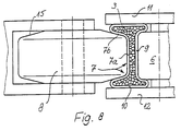
- the clear distance between the tool 8 engaging on the outside of the resulting bend of the profile 2 and the abutment 6 on the other hand, as is particularly clear in FIGS. 3, 5 and 8, is at least temporarily smaller than the height of the side walls, at least during the bending process 10 of the profile 2 and also the dimension A oriented transversely to the longitudinal extent of the profile, ie the area of the abutment 6 which comes into contact with the webs or walls 7 and 9 of the profile and the corresponding dimension B of the tool 8 is less than the profile width and it is also less than the inside clearance of the side walls 10 of the profile 2 the walls and web 7 and 9 are deformed during the bending by the abutment 6 and especially also the tool 8 between the side walls 10 or, in particular, the tool 8 can be immersed between the side walls 10 and the web which is particularly stressed during bending because the external web 7 bring it into an area of a smaller bending radius, where correspondingly lower tensile forces occur.
- Figures 2 u. 3 shows that the cross Dimension A of the abutment 6 oriented to the longitudinal extent of the profile and the corresponding dimension B of the tool 8 is less than the profile width and is even less than the inside clearance of the side walls 10 of the profile 2. 3 even shows that the dimension A of the abutment 6 oriented transversely to the longitudinal direction of the profile and the corresponding dimension B of the tool 8 is even less than the inside clearance of the side walls 10 of the profile 2 by more than two wall thicknesses of the profile webs 10.
- the pressure roller 8 taking part of the outer wall 7 with it, can dip between the side walls 10 into the profile and deform the outer wall 7 against the inner wall 9, which, in turn, will be described below is deformed on the inside, so that both walls 7 and 9 according to Fig. 2 and also according to Fig. 5 come to rest on each other and guide and support each other and, above all, prevent unwanted and uncontrolled distortions and folds.
- Fig. 5 illustrates how the two walls 7 and 9 are gradually brought closer to each other until they actually touch each other in the bending area.
- the narrower bending roller 8 and the hold-down devices 11 and 12 to be described below bring about the targeted and precise deformation of the individual webs 7 and 9, so that these are partially almost parallel to the outer walls 10 within the bend run.
- This not only allows the desired tight bend, but also leads to a correspondingly stiff and stable shape in the bend area despite the previous deformations.
- very thin-walled hollow profiles with tight bends with the smallest possible radius of curvature on the inside can be produced with the device 1 according to the invention.
- the pressure roller 8 is bevelled all around on its side surfaces 14 near its circumference, which acts as a working surface 13.
- This inclination is designated by 15 in FIG. 3 clearly shows that the greater width of the pressure roller 8 is equal to or less than the inside clearance of the side walls 10 of the profile 2 and that the narrower area 13 of the pressure roller 8 is approximately the width of an outside of the profile 2
- the bevels 15 on the side surfaces 14 of the bending or pressure roller 8 have a radial width which is the same or - in the exemplary embodiment - greater than the immersion depth of the bending roller 8 when bending and pressing in the outer web 7 in the direction of the abutment 6.
- a piece of the bevel 15 protrudes from the profile 2 after the roller 8 has been pressed into it.
- the abutment 6, which has already been mentioned several times, is important for a rapid and problem-free course of the deformation during bending.
- This is a shaped piece that is somewhat modified in the various exemplary embodiments, the outer contour of which corresponds to the inner contour of the inner bend to be produced, as is illustrated, for example, in FIG. 5 .
- the abutment 6 protrudes at least temporarily during the bend in relation to the two inner sides or webs of the frame legs which are at an angle to one another after the bend, in the direction towards the outer side of the bend and the profile, so that the inner side of the bend thus receives an indentation, as in Fig.1 and especially in Fig.5, but also in Fig. 3 is clear.
- the abutment 6 or the fitting serving as an abutment can be adapted to adapt to different profiles, web thicknesses, web shapes or the like. be interchangeable.
- the bending device 1 can thus also be used above all for profiles of different dimensions. If necessary, it is also expedient to make the pressure roller 8 interchangeable.
- the abutment 6 can be moved or displaced deeper and deeper into the bend in the manner to be described during the bending process, possibly controlled.
- the inner wall 9 and outer wall 7 of the profile actually touch.
- the pivotable and / or displaceable abutment 6 is arranged immediately adjacent in the feed direction behind the clamping device 4 for detecting the profile area located before the bend. It is therefore separate from this clamping device 4, so it can be independent of these movements to optimize the bending process.
- the abutment 6 has a continuation 16 as a stop for the leg to be bent behind the bend at its pressure region which bears against the inside of the bend which arises during the bending.
- the abutment 6, with its continuation 16 serving as a stop can be pivoted together during the bending process with a bending stop 17 which acts on the outside of the frame leg, the profile being clamped between the abutment continuation 16 and this bending stop 17, so that these parts practically form the device 5 for detecting the leg to be bent.
- Fig. 7 are this device 5 and the abutment 6 with its continuation independently.
- Figures 1.4 and 5 show a particularly expedient embodiment, in which the abutment 6 has a protrusion 6a projecting laterally and in particular eccentrically relative to its extension 16 for pressing into the resulting inside of the bend, the dimension of which in the direction of its pivoting in the The sense increases that by pivoting the continuation 16 and the abutment 6 according to the arrow Pf 1 in FIG. 4, the projection 6a increasingly penetrates deeper into the inside of the bend, as can be clearly seen when comparing FIGS. 4 and 5.
- dimension lines L are shown in the area of the projection 6a, starting from a central point M in each case to the periphery of the projection 6a, in order to increase the eccentricity of the projection 6a due to their length, which is increasing in the direction of the arrow Pf 1 caused gradually greater penetration of the abutment 6 to illustrate the profile 2.
- the arrow Pf 1 is also shown in FIG. 1.
- the outside of the projection 6a is also pivoted and the wall 9 pulls to a certain extent. Modified solutions with regard to the gradual deeper entry of the abutment 6 into the inside of the bend are shown in FIGS.
- the abutment and a continuation 16 located on it are arranged at an acute angle to the incoming, not yet bent profile 2 and are slidably mounted in this orientation according to arrows Pf 2 and Pf 3.
- the area of the inside of the resulting bend are indented inwards, in which case the shaped part forming the abutment 6 has practically an arcuate or circular arc-shaped outer contour.
- the pivoting movement of the pivotable abutment 6 with its continuation 16 which acts with its surface on the inside of the bend in the sense of the profile feed during the pivoting, has at least one displacement movement directed in the direction of orientation of the continuation 16 according to the double arrow Pf 2, in the exemplary embodiment, such a displacement movement shortly after the beginning of the bend and a further displacement movement of this type shortly before completion of the bend is superimposed.
- the abutment 6 and its continuation 16 has a projection 19 engaging in a control curve 18, the control curve 18 being oriented essentially in accordance with the pivoting of this projection 19 when the abutment 6 is pivoted and Deflections 18a for the superimposed displacement movements.
- hold-down device 11 or a support 12 and a hold-down device 11 are provided for the side walls 10 of the profile 2 in the bending area, the distance between which can be adjusted to the width of the profile 2 and the subsequent clear distance between two glass panes. Evasive movements of the side walls 10 are thus avoided during the bending process, as is particularly illustrated by FIG. 3. At least one of these hold-downs 11, which acts on both sides of the profile 2 on its side walls 10, can be delivered and moved away again from the area of the profile 2, which not only facilitates the insertion and removal of the profile 2 or the curved frame, but also the adaptation facilitated to different profile widths.
- an ejector or the like directed by the abutment 6 against the inside of the bend can be in the area of the bending tool 8 in a manner not shown in detail. be provided, which makes it easier to remove the deformed profile after bending. If necessary, even the abutment 6 could serve as an ejector, especially in the solution according to FIG. 7, by a further displacement in the direction of the arrow Pf 3.
- the device 1 can be used, for example, to bend hollow spacer profiles filled with desiccant to form spacer frames for insulating glass panes.
- This can of course be done in a number of ways.
- FIG. 6 shows a solution for such a case in which the hollow profile 2 is perforated on the inside of the bend that is created, so that the desiccant later also becomes effective against the space between the panes.
- FIG. 6 shows in the area of the inside of the bend on the bending device 1 a device for at least temporarily displacing or removing desiccant 3 from the area to be bent in the form of a compressed air nozzle 20 directed against the perforation of the profile 2
- Compressed air nozzle 20 serving to displace drying agent 3 from the bending area is arranged near the abutment 6 and the clamping device 4 arranged on the inside. In this case, it even passes through this clamping device 4 and opens directly in front of the bending area and in front of the abutment 6, so that the air can blow the bending area free.
- the air nozzle 20 is directed obliquely against the inside of the area of the profile 2 located before the bend and includes an acute angle with the leg remaining before the bend and the direction of advance of the profile 2 when it is inserted into the bending device 1 .
- a larger part of the desiccant 3 will be blown forward in the direction of extension of the profile 2, while a part will also be blown back by the resulting excess pressure.
- Fig. 6 it can be clearly seen that the bending area itself is free of the desiccant, while it has accumulated somewhat on both sides of this desiccant-free area because it has been displaced by the compressed air.
- the bend can thus be carried out, in particular with continued blowing in of air are without the desiccant 3 hindering this, so that the walls 7 and 9 can touch 3 despite the desiccant 3 according to FIG.
- desiccant could even remain in the bending area or get back there, since, according to FIG. 3, a space remains or can remain between the inwardly deformed web areas 7b and the side walls 10.
- Another possibility is to first bend an empty profile 2 and then fill in desiccant subsequently, in particular before the profile is finally closed, or even before the last bend is carried out, although it is not absolutely necessary for all the legs of the frame to subsequently be complete are filled with desiccant.
- bending roller 8 can be interchangeable to adapt to different and, above all, different widths 2.
Landscapes
- Engineering & Computer Science (AREA)
- Mechanical Engineering (AREA)
- Civil Engineering (AREA)
- Structural Engineering (AREA)
- Bending Of Plates, Rods, And Pipes (AREA)
- Securing Of Glass Panes Or The Like (AREA)
- Re-Forming, After-Treatment, Cutting And Transporting Of Glass Products (AREA)
- Making Paper Articles (AREA)
Claims (23)
- Appareil (1) pour plier un profil creux (2) - de préférence en vue de la fabrication d'un cadre d'écartement creux, rempli en particulier de desséchant (3), pour vitres isolantes -, comprenant un dispositif de serrage (4) situé à peu près dans la direction d'amenée du profil (2) et destiné à saisir la partie du profil se trouvant devant le pli ou courbure formé au pliage, un mécanisme (5) pour saisir la partie du profil à rabattre ou à changer d'orientation, ainsi qu'un contre-appui (6) pour fixer le côté intérieur du pli ou de la courbure formé et un outil (8) déplaçable sur le côté extérieur du point de pliage sous une pression d'application, par rapport au contre-appui (6) et du profil (2), outil qui peut être pressé contre le côté extérieur du profil et a notamment la forme d'un cylindre ou d'un galet presseur (8) ou analogue, agissant sur au moins une partie de la paroi (7) du profil située sur le côté extérieur de la courbure, appareil dans lequel la distance libre entre l'outil (8) attaquant le côté extérieur de la courbure formée du profil (2) et le contre-appui (6) situé en regard de lui sur le côté intérieur, est inférieure, tout au moins temporairement pendant au moins l'opération de pliage, à la hauteur des parois latérales (10) du profil (2), caractérisé en ce
qu'au moins temporairement pendant au moins l'opération de pliage, la distance libre entre l'outil (8) et le contre-appui (6) est au moins égale à l'épaisseur totale des deux parois (7, 9) du profil creux sollicitées par eux et disposées parallèlement à eux et l'une par rapport à l'autre, ou égale à l'épaisseur totale de ces deux parois (7, 9) plus une couche intermédiaire de desséchant, dont l'étendue est de préférence réduite par rapport à la hauteur totale du profil, et que la dimension (A) orientée transversalement à le'tendue longitudinale du profil, de la face utile du contre-appui (6) et de l'outil (8) est inférieure d'au moins deux épaisseurs des parois (10) du profil à la dimension intérieure libre des parois latérales (10) du profil (2), de telle manière que le contre-appui (6) et l'outil (8) pénètrent entre les parois latérales (10) du profil en enfonçant les parois extérieures (7, 9) chargées par eux. - Appareil selon la revendication 1, caractérisé en ce que les parois (7, 9) sur lesquelles agissent le contre-appui (6) et l'outil (8), sont mutuellement appuyées de manière plane par leurs faces dirigées l'une vers l'autre, indirectement ou directement, pendant le pliage.
- Appareil selon la revendication 1 ou 2, caractérisé en ce que le galet presseur (8) est biseauté (15) de façon continue tout autour à ses faces latérales (14) près de sa surface périphérique agissant en tant que surface de travail (13), que la plus grande largeur du galet presseur (8) est supérieure, égale ou inférieure à la distance intérieure libre des parois latérales (10) du profil (2) et que la partie plus étroite (13) du galet presseur (8) possède une largeur correspondant à peu près à la largeur d'une portion de paroi (7a) située à l'extérieur du profil (2) et dont des portions de paroi obliques (7b) descendent vers les parois latérales (10).
- Appareil selon la revendication 3, caractérisé en ce que les biseaux (15) sur les faces latérales (14) du galet de pliage ou galet presseur (8) ont une largeur radiale qui est égale ou supérieure à la profondeur de pénétration du galet (8) lors du pliage et de l'enfoncement de la paroi extérieure (7) en direction du contre-appui (6).
- Appareil selon une des revendications 1 à 4, caractérisé en ce que le contre-appui (6), situé sur le côté intérieur de la courbure, est une pièce façonnée dont le contour extérieur correspond au contour intérieur de la courbure intérieure à réaliser et qui fait saillie, au moins temporairement, pendant le pliage, par rapport aux deux côté intérieurs ou aux deux parois intérieures des parties du cadre formant un angle entre eux après le pliage, en direction du côté extérieur de la courbure et du profil, de manière que le côté intérieur de la courbure soit pourvu d'un congé.
- Appareil selon une des revendications 1 à 5, caractérisé en ce que le contre-appui (6) ou la pièce façonnée servant de contre-appui, est interchangeable en vue de l'adaptation à différents profils, épaisseurs de paroi, formes de paroi ou analogues.
- Appareil selon une des revendications 1 à 6, caractérisé en ce que le contre-appui (6) peut être mû ou déplacé en translation, pendant l'opération de pliage, notamment de façon commandée, dans le sens de son engagement plus profond dans la courbure.
- Appareil selon une des revendications 1 à 7, caractérisé en ce que le contre-appui (6), susceptible d'être animé d'un pivotement et/ou d'un mouvement de translation, est disposé à proximité immédiate, dans la direction d'avancement, du dispositif de serrage (4) destiné à saisir la partie du profil se trouvant devant la courbure.
- Appareil selon une des revendications 1 à 8, caractérisé en ce que le contre-appui (6) possède un prolongement (16) raccordé à sa zone de pression appliqué pendant le pliage contre le côté intérieur de la courbure formée, prolongement qui sert de butée pour la partie du profil à rabattre ou à changer d'orientation.
- Appareil selon une des revendications 1 à 9, caractérisé en ce que le contre-appui (6) et son prolongement (16), servant de butée, sont susceptibles d'être animés d'un mouvement de pivotement, lors de l'opération de pliage, ensemble avec une butée de pliage (17) agissant sur le côté extérieur de la branche ou partie du cadre à rabattre, le profil étant de préférence serré entre le prolongement (16) du contre-appui et cette butée de pliage (17).
- Appareil selon une des revendications 1 à 10, caractérisé en ce que le contre-appui (6) s'étend ou peut être mû ou déplacé en translation pour s'étendre à peu près jusque dans la zone de la fibre neutre du profil (2) à plier.
- Appareil selon une des revendications 1 à 11, caractérisé en ce que le contre-appui (6) possède une saillie (6a), dépassant de préférence latéralement et en particulier excentriquement par rapport à son prolongement (16), qui est destinée à être enfoncée dans le côté intérieur formé de la courbure et dont la dimension augmente dans le sens de son pivotement, de manière que, par suite du pivotement du prolongement (16) et du contre-appui (6), la saillie (6a) pénètre de plus en plus dans le côté intérieur de la courbure.
- Appareil selon une des revendications 1 à 12, caractérisé en ce que le contre-appui (6) et un prolongement (16) prévu sur lui, sont disposés sous un angle aigu par rapport au profil (2) arrivant, non encore plié, et sont montés de façon à pouvoir être déplaçables en translation suivant leur direction d'orientation.
- Appareil selon une des revendications 1 à 13, caractérisé en ce que, au mouvement de pivotement du contre-appui (6) pivotant, agissant par sa surface sur le côté intérieur de la courbure dans le sens de l'avancement du profil pendant le pivotement, est superposé au moins un mouvement de translation dirigé suivant l'orientation du prolongement (16) du contre-appui, ou sont superposés, de préférence, un tel mouvement de translation produit peu après le début du pliage et un autre mouvement de translation de ce type produit peu avant l'achèvement du pliage.
- Appareil selon la revendication 14, caractérisé en ce que le contre-appui (6) et/ou son prolongement (16) possède un tenon (19) ou un élément analogue pénétrant dans une fente de guidage ou de commande (18) ou un dispositif semblable, la fente de commande (18) étant orientée essentiellement suivant le trajet de pivotement de ce tenon (19) lors du pivotement du contre-appui (6) et comportant des déviations (18a) pour produire les mouvements de translation superposés.
- Appareil selon une des revendications 1 à 15, caractérisé en ce que des éléments de maintien (11) ou un support (12) et un élément de maintien (11), ou des éléments de guidage semblables pour les parois latérales (10) du profil (2) sont prévus dans la zone de pliage, éléments dont l'espacement est ajustable à la largeur du profil (2) et à la distance intérieure libre formée ultérieurement entre deux vitres.
- Appareil selon la revendication 16, caractérisé en ce que l'un au moins des éléments de maintien (11) ou analogues, disposés des deux côtés du profil (2) et attaquant les parois latérales (10) de ce profil, peut être serré contre le profil et peut être écarté de nouveau hors de la zone du profil (2).
- Appareil selon une des revendications 1 à 17, caractérisé en ce qu'un éjecteur ou un dispositif semblable, dirigé par le contre-appui (6) vers le côté intérieur de la courbure, est prévu dans la zone de l'outil de pliage (8).
- Appareil pour plier un profil d'entretoisement creux, rempli de desséchant, pour vitres isolantes, selon une des revendications 1 à 18, caractérisé en ce que, pendant l'opération de pliage, l'intérieur du profil (2) est complètement ou au moins partiellement exempt de desséchant (3) dans la zone de pliage.
- Appareil pour plier un profil creux rempli de desséchant et perforé sur le côté intérieur de la courbure formée, selon la revendication 19, caractérisé en ce que, dans la zone du côté intérieur de la courbure, on a prévu, sur l'appareil de pliage (1), un dispositif pour au moins temporairement refouler ou éliminer le desséchant (3) de la zone du profil à plier, en particulier une buse à air comprimé (20) dirigée vers la perforation du profil (2).
- Appareil selon la revendication 20, caractérisé en ce que la buse à air comprimé (20), servant à refouler le desséchant (3) hors de la zone de pliage, est placée près du contre-appui (6) et/ou du dispositif de serrage (4) prévu sur le côté intérieur, de préférence de manière qu'elle traverse ce dispositif de serrage (4) pour déboucher directement devant la zone de pliage du profil.
- Appareil selon une des revendications 20 ou 21, caractérisé en ce que la buse à air (20) est dirigée obliquement contre le côté intérieur de la partie du profil (2) se trouvant devant la courbure et renferme un angle aigu avec cette partie du profil et la direction d'avancement du profil (2) lors de l'introduction dans l'appareil de pliage (1).
- Appareil selon une des revendications précédentes, caractérisé en ce que le galet de pliage (8) est interchangeable en vue de l'adaptation à différents profils (2) et, surtout, à des profils (2) de différentes largeurs.
Priority Applications (1)
| Application Number | Priority Date | Filing Date | Title |
|---|---|---|---|
| AT88118909T ATE80071T1 (de) | 1987-12-03 | 1988-11-12 | Vorrichtung zum biegen eines hohlprofiles insbesondere eines abstandhalter-rahmens fuer isolierglasscheiben. |
Applications Claiming Priority (2)
| Application Number | Priority Date | Filing Date | Title |
|---|---|---|---|
| DE19873740921 DE3740921A1 (de) | 1987-12-03 | 1987-12-03 | Vorrichtung zur herstellung einer biegung an einem hohlen rechteck-profil |
| DE3740921 | 1987-12-03 |
Publications (4)
| Publication Number | Publication Date |
|---|---|
| EP0318748A2 EP0318748A2 (fr) | 1989-06-07 |
| EP0318748A3 EP0318748A3 (en) | 1990-06-13 |
| EP0318748B1 EP0318748B1 (fr) | 1992-09-02 |
| EP0318748B2 true EP0318748B2 (fr) | 1997-12-17 |
Family
ID=6341773
Family Applications (1)
| Application Number | Title | Priority Date | Filing Date |
|---|---|---|---|
| EP88118909A Expired - Lifetime EP0318748B2 (fr) | 1987-12-03 | 1988-11-12 | Dispositif de pliage d'un profil creux, en particulier un cadre de barres d'écartement pour vitres isolantes |
Country Status (5)
| Country | Link |
|---|---|
| US (1) | US4945619A (fr) |
| EP (1) | EP0318748B2 (fr) |
| AT (1) | ATE80071T1 (fr) |
| DE (2) | DE3740921A1 (fr) |
| ES (1) | ES2035221T5 (fr) |
Cited By (4)
| Publication number | Priority date | Publication date | Assignee | Title |
|---|---|---|---|---|
| DE19733536A1 (de) * | 1997-08-02 | 1999-02-18 | Bayer Isolierglasfab Kg | Vorrichtung zum Biegen eines Hohlprofiles mit einem Niederhalter |
| DE19839444C1 (de) * | 1998-08-29 | 2000-01-05 | Bayer Isolierglasfab Kg | Verfahren und Vorrichtung zum Biegen eines Hohlprofiles zur Herstellung eines Abstandhalter-Rahmens für Isolierglasscheiben |
| DE19956046B4 (de) * | 1999-11-22 | 2004-12-30 | Bayer Isolierglas- Und Maschinentechnik Gmbh | Verfahren und Vorrichtung zur Herstellung eines Abstandhalterrahmens für Isolierglasscheiben |
| DE19839735B4 (de) * | 1998-09-01 | 2005-03-03 | Franz Xaver Bayer Isolierglasfabrik Kg | Vorrichtung zum Biegen eines abstandhaltenden Innenrahmens für eine Isolierglasscheibe |
Families Citing this family (29)
| Publication number | Priority date | Publication date | Assignee | Title |
|---|---|---|---|---|
| DE3829290A1 (de) * | 1988-08-30 | 1990-03-15 | Bayer Ag | Polyetherpolyole auf basis aromatischer di- und/oder polyamine, verfahren zu ihrer herstellung und verwendung fuer polyurethan- und polyisocyanurat-kunststoffe |
| DE3942809A1 (de) * | 1989-12-23 | 1991-06-27 | Bayer Isolierglasfab Kg | Verfahren und vorrichtung zum herstellen eines abstandhaltenden rahmens insbesondere fuer isolierglasscheiben |
| DE3942808A1 (de) * | 1989-12-23 | 1991-06-27 | Bayer Isolierglasfab Kg | Verfahren und vorrichtung zum herstellen eines abstandhalter-rahmens |
| DE4104997A1 (de) * | 1990-02-21 | 1991-08-29 | Bernhard Kreye | Verfahren und vorrichtung zum biegen von profilierten hohlstaeben, insbesondere zum biegen von hohlprofilen fuer fenster und tuerrahmen |
| AT397054B (de) * | 1990-05-21 | 1994-01-25 | Lisec Peter | Vorrichtung zum biegen von hohlprofilleisten |
| EP0459971B2 (fr) * | 1990-05-21 | 2001-12-12 | Peter Lisec | Procédé et dispositif pour obtenir des parties pliées dans les profilés d'écartement creux |
| DK0462961T3 (da) * | 1990-05-21 | 1994-04-05 | Peter Lisec | Apparat til bøjning af hulprofillister |
| US5243844A (en) * | 1990-05-21 | 1993-09-14 | Peter Lisec | Process for producing curved sections in hollow profile strips |
| AT405912B (de) * | 1990-10-02 | 1999-12-27 | Lisec Peter | Verfahren und vorrichtung zum krümmen von hohlprofilleisten |
| DE59100838D1 (de) * | 1990-06-07 | 1994-02-24 | Peter Lisec | Verfahren und Vorrichtung zum Biegen von Hohlprofilleisten zu Abstandhalterrahmen für Isolierglasscheiben. |
| AT397055B (de) * | 1990-06-07 | 1994-01-25 | Lisec Peter | Verfahren und vorrichtung zum biegen von hohlprofilleisten zu abstandhalterrahmen für isolierglasscheiben |
| DK169909B1 (da) * | 1990-10-26 | 1995-04-03 | Bayer Isolierglasfab Kg | Bukkemaskine |
| DK9192A (da) * | 1992-01-24 | 1993-07-25 | Skovgaard & Co As | Fremgangsmaade samt apparat til bukning af tyndvaegget, hult afstandsprofil |
| DE4225833C2 (de) * | 1992-08-05 | 1994-07-28 | Bayer Isolierglasfab Kg | Biegevorrichtung für Hohlprofile |
| IT1266114B1 (it) * | 1993-08-02 | 1996-12-20 | For El Base Di Vianello Fortun | Dispositivo per il riempimento di telai distanziatori per vetro-camera con materiale igroscopico |
| FR2774624B1 (fr) * | 1998-02-10 | 2000-03-10 | Seva | Procede de pliage de profiles comportant un corps creux et une feuille de revetement, et profile plie par ce procede |
| FR2774625B1 (fr) * | 1998-02-10 | 2000-03-10 | Seva | Procede de pliage de profiles comportant un corps creux et une feuille de revetement,et profile plie par ce procede |
| US6601291B2 (en) * | 2001-06-14 | 2003-08-05 | Georgia-Pacific Resins, Inc. | Apparatus and method of producing a core board product |
| DE10137766A1 (de) * | 2001-08-03 | 2003-02-27 | Lenhardt Maschinenbau | Vorrichtung zum Biegen von Hohlprofilstäben |
| DE10138345B4 (de) * | 2001-08-03 | 2008-12-04 | Lenhardt Maschinenbau Gmbh | Vorrichtung zum Biegen von Hohlprofilstäben |
| US6619098B2 (en) | 2001-08-28 | 2003-09-16 | Peter Lisec | Process and device for bending of hollow profile strips into spacer frames for insulating glass panes |
| DE10236373B4 (de) * | 2002-08-02 | 2007-10-11 | Takata Corp. | Verfahren zum Biegen eines Füllrohres für ein Airbagmodul und Vorrichtung zur Durchführung dieses Verfahrens |
| DE102004060805A1 (de) * | 2004-11-05 | 2006-05-11 | Lenhardt Maschinenbau Gmbh | Verfahren und Vorrichtung zum Biegen von Hohlprofilstäben, insbesondere für Abstandhalterrahmen von Isolierglasscheiben |
| EP2288777A2 (fr) * | 2008-04-11 | 2011-03-02 | Plus Inventia AG | Procédé de production d'un angle d'un intercalaire en forme de cadre pour vitrages isolants et intercalaires et vitrages isolants produits par ce procédé |
| JP5233682B2 (ja) * | 2009-01-08 | 2013-07-10 | アイシン・エィ・ダブリュ株式会社 | 曲げ加工機 |
| CN102248041A (zh) * | 2010-05-17 | 2011-11-23 | 赵士平 | 中空玻璃铝隔条折弯机中的定位装置 |
| US10183363B2 (en) | 2015-08-04 | 2019-01-22 | Cardinal Ig Company | Spacer formation cell |
| HUE049058T2 (hu) * | 2017-03-10 | 2020-08-28 | Allmetal Inc | Szigetelõüveg-távtartószerkezet |
| CN115178620B (zh) * | 2022-07-04 | 2025-03-25 | 山东能特异能源科技有限公司 | 用于中空玻璃的封填式间隔条的折弯方法 |
Family Cites Families (8)
| Publication number | Priority date | Publication date | Assignee | Title |
|---|---|---|---|---|
| GB624169A (en) * | 1944-11-21 | 1949-05-30 | Sncase | Improvements in machines for bending angle and other metal rods, bars or the like |
| US3553990A (en) * | 1968-04-23 | 1971-01-12 | Pines Engineering Co Inc | Tube bender pressure die interference control |
| CA1134125A (fr) * | 1978-06-14 | 1982-10-26 | Theo Janssens | Panneaux creux, et dispositif et methode de fabrication connexes |
| CH660398A5 (de) * | 1982-01-21 | 1987-04-15 | Peter Lisec | Abstandhalterrahmen fuer isolierglasscheiben sowie verfahren zur herstellung desselben und vorrichtung zur durchfuehrung des verfahrens. |
| DE3312764A1 (de) * | 1983-04-09 | 1984-10-18 | Fr. Xaver Bayer Isolierglasfabrik Kg, 7807 Elzach | Verfahren und vorrichtung zum biegen von abstandhalter-profilen fuer isolierglasscheiben |
| CA1246978A (fr) * | 1983-04-09 | 1988-12-20 | Franz Bayer | Methode et dispositif de fabrication d'entre-deux pour vitrages doubles, triples et leurs analogues |
| DE3346671C1 (de) * | 1983-12-23 | 1985-07-04 | Karl 7531 Neuhausen Lenhardt | Verfahren zum Formen der Ecken von Abstandhalterrahmen fuer randverklebte Isolierglasscheiben |
| DE3740922A1 (de) * | 1987-12-03 | 1989-06-22 | Bayer Isolierglasfab Kg | Verfahren und vorrichtung zur herstellung eines abstandhalter-rahmens |
-
1987
- 1987-12-03 DE DE19873740921 patent/DE3740921A1/de active Granted
-
1988
- 1988-11-12 AT AT88118909T patent/ATE80071T1/de not_active IP Right Cessation
- 1988-11-12 EP EP88118909A patent/EP0318748B2/fr not_active Expired - Lifetime
- 1988-11-12 DE DE8888118909T patent/DE3874298D1/de not_active Expired - Lifetime
- 1988-11-12 ES ES88118909T patent/ES2035221T5/es not_active Expired - Lifetime
- 1988-12-05 US US07/280,090 patent/US4945619A/en not_active Expired - Lifetime
Cited By (5)
| Publication number | Priority date | Publication date | Assignee | Title |
|---|---|---|---|---|
| DE19733536A1 (de) * | 1997-08-02 | 1999-02-18 | Bayer Isolierglasfab Kg | Vorrichtung zum Biegen eines Hohlprofiles mit einem Niederhalter |
| DE19733536C2 (de) * | 1997-08-02 | 2001-10-11 | Bayer Isolierglasfab Kg | Biegevorrichtung mit einem Niederhalter für Hohlprofile |
| DE19839444C1 (de) * | 1998-08-29 | 2000-01-05 | Bayer Isolierglasfab Kg | Verfahren und Vorrichtung zum Biegen eines Hohlprofiles zur Herstellung eines Abstandhalter-Rahmens für Isolierglasscheiben |
| DE19839735B4 (de) * | 1998-09-01 | 2005-03-03 | Franz Xaver Bayer Isolierglasfabrik Kg | Vorrichtung zum Biegen eines abstandhaltenden Innenrahmens für eine Isolierglasscheibe |
| DE19956046B4 (de) * | 1999-11-22 | 2004-12-30 | Bayer Isolierglas- Und Maschinentechnik Gmbh | Verfahren und Vorrichtung zur Herstellung eines Abstandhalterrahmens für Isolierglasscheiben |
Also Published As
| Publication number | Publication date |
|---|---|
| DE3874298D1 (de) | 1992-10-08 |
| US4945619A (en) | 1990-08-07 |
| ES2035221T5 (es) | 1998-04-16 |
| ATE80071T1 (de) | 1992-09-15 |
| EP0318748B1 (fr) | 1992-09-02 |
| ES2035221T3 (es) | 1993-04-16 |
| EP0318748A2 (fr) | 1989-06-07 |
| DE3740921A1 (de) | 1989-06-15 |
| DE3740921C2 (fr) | 1989-09-21 |
| EP0318748A3 (en) | 1990-06-13 |
Similar Documents
| Publication | Publication Date | Title |
|---|---|---|
| EP0318748B1 (fr) | Dispositif de pliage d'un profil creux, en particulier un cadre de barres d'écartement pour vitres isolantes | |
| EP2529849B1 (fr) | Dispositif et procédé de fabrication de tuyaux fendus à partir de plaques de tôle | |
| EP1796859B1 (fr) | Procede et dispositif pour produire un profile creux a soudure longitudinale | |
| EP0318749B1 (fr) | Méthode et dispositif pour construire des cadres d'écartement | |
| DE19717472A1 (de) | Verfahren und Vorrichtung zum Profilbiegen mit modularen Biegestationen | |
| EP0121873A2 (fr) | Procédé et dispositif de pliage de barres d'écartement pour vitres isolantes | |
| EP1089835A1 (fr) | Procede et dispositif pour la production de tubes a cordons de soudure longitudinaux a partir de decoupes de tole | |
| EP3820631B1 (fr) | Presse à former à jco à réglage élargi | |
| DE2642743B2 (de) | Vorrichtung zum Herstellen einer Kraftfahrzeug-Achse | |
| WO2009023973A1 (fr) | Procédé et dispositif pour former un tube à partir d'une tôle | |
| EP1954420B1 (fr) | Procede et dispositif de moulage sans noyau de profiles creux | |
| DE102004041024B4 (de) | Verfahren und Vorrichtung zum Herstellen eines längsnahtgeschweißten Hohlprofils | |
| DE19733536C2 (de) | Biegevorrichtung mit einem Niederhalter für Hohlprofile | |
| DE102018115382B4 (de) | Verbinden von Blechendabschnitten mittels Umformen | |
| DE19956046B4 (de) | Verfahren und Vorrichtung zur Herstellung eines Abstandhalterrahmens für Isolierglasscheiben | |
| DE2843531C2 (de) | Maschine zum Herstellen von gitterträgerartigen Bewehrungsgebilden für Stahlbeton | |
| DE102020133419B4 (de) | Anordnung, Verfahren und Richteinheit zum Rundbiegen des Endbereichs mit den beiden Enden spitzgebogener Rohre mit einer 3-Walzen-Biegemaschine | |
| EP2189229A1 (fr) | Procédé destiné à fermer l'extrémité de tuyaux dotés d'une section transversale rectangulaire | |
| EP0665357B1 (fr) | Procédé et dispositif pour la fabrication d'un cadre espaceur pour vitrages isolants | |
| DE7929990U1 (de) | Vorrichtung zur herstellung von anschlagbaendern, tuer- und fensterangeln u.dgl. | |
| EP0042450A1 (fr) | Procédé pour la fabrication d'enveloppes de pots d'échappement à joint longitudinal plié et dispositif pour la réalisation de ce procédé | |
| DE9401813U1 (de) | Richt-Maschine | |
| DD287148A7 (de) | Werkzeug zur herstellung eines kegelstumpf-rohrfoermigen blechteiles |
Legal Events
| Date | Code | Title | Description |
|---|---|---|---|
| PUAI | Public reference made under article 153(3) epc to a published international application that has entered the european phase |
Free format text: ORIGINAL CODE: 0009012 |
|
| AK | Designated contracting states |
Kind code of ref document: A2 Designated state(s): AT BE CH DE ES FR GB IT LI NL SE |
|
| PUAL | Search report despatched |
Free format text: ORIGINAL CODE: 0009013 |
|
| AK | Designated contracting states |
Kind code of ref document: A3 Designated state(s): AT BE CH DE ES FR GB IT LI NL SE |
|
| 17P | Request for examination filed |
Effective date: 19900620 |
|
| 17Q | First examination report despatched |
Effective date: 19910610 |
|
| GRAA | (expected) grant |
Free format text: ORIGINAL CODE: 0009210 |
|
| AK | Designated contracting states |
Kind code of ref document: B1 Designated state(s): AT BE CH DE ES FR GB IT LI NL SE |
|
| REF | Corresponds to: |
Ref document number: 80071 Country of ref document: AT Date of ref document: 19920915 Kind code of ref document: T |
|
| ITF | It: translation for a ep patent filed | ||
| REF | Corresponds to: |
Ref document number: 3874298 Country of ref document: DE Date of ref document: 19921008 |
|
| ET | Fr: translation filed | ||
| GBT | Gb: translation of ep patent filed (gb section 77(6)(a)/1977) |
Effective date: 19921130 |
|
| REG | Reference to a national code |
Ref country code: ES Ref legal event code: FG2A Ref document number: 2035221 Country of ref document: ES Kind code of ref document: T3 |
|
| PLBI | Opposition filed |
Free format text: ORIGINAL CODE: 0009260 |
|
| PLBI | Opposition filed |
Free format text: ORIGINAL CODE: 0009260 |
|
| 26 | Opposition filed |
Opponent name: GLASTECHNISCHE INDUSTRIE PETER LISEC GMBH, Effective date: 19930601 |
|
| 26 | Opposition filed |
Opponent name: LENHARDT MASCHINENBAU GMBH Effective date: 19930602 Opponent name: GLASTECHNISCHE INDUSTRIE PETER LISEC GMBH, Effective date: 19930601 |
|
| NLR1 | Nl: opposition has been filed with the epo |
Opponent name: GLASTECHNISCHE INDUSTRIE PETER LISEC GMBH. |
|
| NLR1 | Nl: opposition has been filed with the epo |
Opponent name: LENHARDT MASCHINENBAU GMBH |
|
| EAL | Se: european patent in force in sweden |
Ref document number: 88118909.6 |
|
| APAC | Appeal dossier modified |
Free format text: ORIGINAL CODE: EPIDOS NOAPO |
|
| APAC | Appeal dossier modified |
Free format text: ORIGINAL CODE: EPIDOS NOAPO |
|
| PLAW | Interlocutory decision in opposition |
Free format text: ORIGINAL CODE: EPIDOS IDOP |
|
| APAC | Appeal dossier modified |
Free format text: ORIGINAL CODE: EPIDOS NOAPO |
|
| PUAH | Patent maintained in amended form |
Free format text: ORIGINAL CODE: 0009272 |
|
| STAA | Information on the status of an ep patent application or granted ep patent |
Free format text: STATUS: PATENT MAINTAINED AS AMENDED |
|
| PGFP | Annual fee paid to national office [announced via postgrant information from national office to epo] |
Ref country code: ES Payment date: 19971103 Year of fee payment: 10 |
|
| 27A | Patent maintained in amended form |
Effective date: 19971217 |
|
| AK | Designated contracting states |
Kind code of ref document: B2 Designated state(s): AT BE CH DE ES FR GB IT LI NL SE |
|
| ET3 | Fr: translation filed ** decision concerning opposition | ||
| REG | Reference to a national code |
Ref country code: CH Ref legal event code: AEN Free format text: AUFRECHTERHALTUNG DES PATENTES IN GEAENDERTER FORM |
|
| ITF | It: translation for a ep patent filed | ||
| NLR2 | Nl: decision of opposition | ||
| GBTA | Gb: translation of amended ep patent filed (gb section 77(6)(b)/1977) | ||
| REG | Reference to a national code |
Ref country code: ES Ref legal event code: DC2A Kind code of ref document: T5 Effective date: 19980316 |
|
| NLR3 | Nl: receipt of modified translations in the netherlands language after an opposition procedure | ||
| PGFP | Annual fee paid to national office [announced via postgrant information from national office to epo] |
Ref country code: BE Payment date: 19990517 Year of fee payment: 11 |
|
| PGFP | Annual fee paid to national office [announced via postgrant information from national office to epo] |
Ref country code: SE Payment date: 19990518 Year of fee payment: 11 |
|
| PG25 | Lapsed in a contracting state [announced via postgrant information from national office to epo] |
Ref country code: SE Free format text: LAPSE BECAUSE OF NON-PAYMENT OF DUE FEES Effective date: 19991113 Ref country code: ES Free format text: LAPSE BECAUSE OF NON-PAYMENT OF DUE FEES Effective date: 19991113 |
|
| PG25 | Lapsed in a contracting state [announced via postgrant information from national office to epo] |
Ref country code: BE Free format text: LAPSE BECAUSE OF NON-PAYMENT OF DUE FEES Effective date: 19991130 |
|
| BERE | Be: lapsed |
Owner name: FRANZ XAVER BAYER ISOLIERGLASFABRIK K.G. Effective date: 19991130 |
|
| EUG | Se: european patent has lapsed |
Ref document number: 88118909.6 |
|
| PGFP | Annual fee paid to national office [announced via postgrant information from national office to epo] |
Ref country code: NL Payment date: 20011123 Year of fee payment: 14 |
|
| REG | Reference to a national code |
Ref country code: GB Ref legal event code: IF02 |
|
| PG25 | Lapsed in a contracting state [announced via postgrant information from national office to epo] |
Ref country code: NL Free format text: LAPSE BECAUSE OF NON-PAYMENT OF DUE FEES Effective date: 20030601 |
|
| NLV4 | Nl: lapsed or anulled due to non-payment of the annual fee |
Effective date: 20030601 |
|
| REG | Reference to a national code |
Ref country code: ES Ref legal event code: FD2A Effective date: 20001214 |
|
| APAH | Appeal reference modified |
Free format text: ORIGINAL CODE: EPIDOSCREFNO |
|
| PGFP | Annual fee paid to national office [announced via postgrant information from national office to epo] |
Ref country code: GB Payment date: 20051111 Year of fee payment: 18 |
|
| PG25 | Lapsed in a contracting state [announced via postgrant information from national office to epo] |
Ref country code: IT Free format text: LAPSE BECAUSE OF NON-PAYMENT OF DUE FEES;WARNING: LAPSES OF ITALIAN PATENTS WITH EFFECTIVE DATE BEFORE 2007 MAY HAVE OCCURRED AT ANY TIME BEFORE 2007. THE CORRECT EFFECTIVE DATE MAY BE DIFFERENT FROM THE ONE RECORDED. Effective date: 20051112 |
|
| PGFP | Annual fee paid to national office [announced via postgrant information from national office to epo] |
Ref country code: FR Payment date: 20051122 Year of fee payment: 18 |
|
| GBPC | Gb: european patent ceased through non-payment of renewal fee |
Effective date: 20061112 |
|
| REG | Reference to a national code |
Ref country code: FR Ref legal event code: ST Effective date: 20070731 |
|
| PG25 | Lapsed in a contracting state [announced via postgrant information from national office to epo] |
Ref country code: GB Free format text: LAPSE BECAUSE OF NON-PAYMENT OF DUE FEES Effective date: 20061112 |
|
| PGFP | Annual fee paid to national office [announced via postgrant information from national office to epo] |
Ref country code: DE Payment date: 20071017 Year of fee payment: 20 |
|
| PGFP | Annual fee paid to national office [announced via postgrant information from national office to epo] |
Ref country code: AT Payment date: 20071128 Year of fee payment: 20 Ref country code: CH Payment date: 20071116 Year of fee payment: 20 |
|
| PG25 | Lapsed in a contracting state [announced via postgrant information from national office to epo] |
Ref country code: FR Free format text: LAPSE BECAUSE OF NON-PAYMENT OF DUE FEES Effective date: 20061130 |
|
| REG | Reference to a national code |
Ref country code: CH Ref legal event code: PL |