EP1632308A1 - Guidage linéaire avec deux rails de guidage parallèles et procédé pour sa fabrication - Google Patents
Guidage linéaire avec deux rails de guidage parallèles et procédé pour sa fabrication Download PDFInfo
- Publication number
- EP1632308A1 EP1632308A1 EP04405549A EP04405549A EP1632308A1 EP 1632308 A1 EP1632308 A1 EP 1632308A1 EP 04405549 A EP04405549 A EP 04405549A EP 04405549 A EP04405549 A EP 04405549A EP 1632308 A1 EP1632308 A1 EP 1632308A1
- Authority
- EP
- European Patent Office
- Prior art keywords
- spacer plate
- guide rails
- welding
- linear motion
- carriages
- Prior art date
- Legal status (The legal status is an assumption and is not a legal conclusion. Google has not performed a legal analysis and makes no representation as to the accuracy of the status listed.)
- Granted
Links
- 238000004519 manufacturing process Methods 0.000 title claims description 9
- 125000006850 spacer group Chemical group 0.000 claims description 55
- 230000033001 locomotion Effects 0.000 claims description 39
- 238000003466 welding Methods 0.000 claims description 35
- 238000000034 method Methods 0.000 claims description 15
- 238000005096 rolling process Methods 0.000 description 4
- 230000002411 adverse Effects 0.000 description 2
- 238000011161 development Methods 0.000 description 2
- 230000018109 developmental process Effects 0.000 description 2
- 239000000853 adhesive Substances 0.000 description 1
- 238000004026 adhesive bonding Methods 0.000 description 1
- 230000001070 adhesive effect Effects 0.000 description 1
- 230000001419 dependent effect Effects 0.000 description 1
- 230000000694 effects Effects 0.000 description 1
- 239000012530 fluid Substances 0.000 description 1
- 238000009434 installation Methods 0.000 description 1
- 239000000463 material Substances 0.000 description 1
Images




Classifications
-
- B—PERFORMING OPERATIONS; TRANSPORTING
- B23—MACHINE TOOLS; METAL-WORKING NOT OTHERWISE PROVIDED FOR
- B23Q—DETAILS, COMPONENTS, OR ACCESSORIES FOR MACHINE TOOLS, e.g. ARRANGEMENTS FOR COPYING OR CONTROLLING; MACHINE TOOLS IN GENERAL CHARACTERISED BY THE CONSTRUCTION OF PARTICULAR DETAILS OR COMPONENTS; COMBINATIONS OR ASSOCIATIONS OF METAL-WORKING MACHINES, NOT DIRECTED TO A PARTICULAR RESULT
- B23Q1/00—Members which are comprised in the general build-up of a form of machine, particularly relatively large fixed members
- B23Q1/01—Frames, beds, pillars or like members; Arrangement of ways
- B23Q1/017—Arrangements of ways
Definitions
- the invention relates to a linear motion guide with at least two guide rails and in each case at least one carriage which is supported on the guide rails and can be moved along a longitudinal movement axis of the guide. Furthermore, the invention relates to a method for producing a linear motion guide.
- a carriage In a widespread linear motion guide, a carriage is supported on at least one circulating unit arranged rolling or rolling elements on the guide rail. The carriage is moved along a longitudinal movement axis due to rotation of the rolling elements in the circulation unit on the rail.
- the invention covers not only such linear roller bearing guides but also, for example, those in which the carriage via sliding, fluid or magnetic bearing supported on the rail.
- Linear motion guides are mainly used for translational, in particular rectilinear, movement and guidance of machine parts, as required for example in the movement of the translational axes of a machine tool.
- the linear guides are often used in a heavily soiled environment and under adverse conditions such as high temperatures, they require high precision.
- a prerequisite for ensuring a high precision of the movement of the machine parts is to ensure a great stiffness of leadership. The leadership should therefore not relocate or deform due to stress as possible.
- the natural frequency of the machine part which results from a carrier and the attached linear motion guide, should be as high as possible in a harmless region with a small vibration amplitude.
- Another essential prerequisite for a precise movement of the machine parts is that the rolling elements of the carriage do not pollute, since this has an adverse effect on the wear and the guiding accuracy.
- the guide rails are provided for the most secure and rigid attachment to a support usually with orthogonal to their surface extending through holes, which are provided for receiving fasteners, such as screws.
- the invention is therefore an object of the invention to provide a generic linear motion guide and to propose a method for its production, so that the manufacturing cost is reduced without reducing the requirements for the adjustability of the overall system.
- the measures of the invention initially have the consequence that stop surfaces on the two guide rails continue to represent the Justier vom for the entire system.
- the surfaces of the carriages also provide upper adjustment surfaces.
- the accuracy of the linear motion guide is ensured in a preferred embodiment by the highly accurate welds with the aid of gauges.
- the connection is made - preferably also with a gauge - by gluing.
- the accuracy of the installation is ensured by stop surfaces on the guide rails or the carriage and does not have to be removed by appropriate surfaces on the spacer plates.
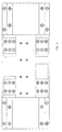
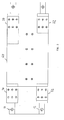
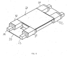
- two guide rails 10 and 12 of the previously known type are provided. Between these guide rails a spacer plate 20 is welded.
- the welding operation is carried out in the present embodiment so that the welding is carried out with the aid of a welding jig, are introduced into the two guide rails for defining a predetermined distance.
- the lower spacer plate 20 is then welded by laser welding.
- the welding is carried out as line welding in each case over sections of about 20 to 50 mm.
- Such a weld is made from both sides - top and bottom. It has been shown that a single weld - so only at the top or bottom - does not lead to the required stability.
- the lower spacer plate is chamfered before welding at the top.
- the weld can be practically sunk into the chamfer of the plate.
- the guide rails are each chamfered on the side facing the lower spacer plate, whereby then the lower weld can also be sunk.
- the underside of the lower spacer plate during welding is arranged so that it remains above the underside of the guide rails after welding.
- an upper spacer plate 60 is laser-welded shrink wrapped. This welding is also carried out as a line welding over a section. The line welding is again carried out in each case from both sides of the weld seam between the guide rails and the upper spacer plate.
- the upper spacer plate is chamfered before welding on the side. Also, the outer edges of the carriages are each chamfered on the upper spacer plate facing side.
- the top of the upper spacer plate is also arranged during welding so that it remains below the tops of the carriage after welding.
- the drive is mounted as a linear drive on the two spacer plates 20 and 60.
- the drive can also be designed in any way already known for such linear drives.
- the upper spacer plate is approximately rectangular in shape. Starting from their corners, two welds on the front are made by two carriages and two welds on the back by two more carriages. In this embodiment, the upper spacer plate is thus arranged between the carriages.
- the upper spacer plate is approximately rectangular with four rectangular cut-outs at its corners.
- the carriages are then welded at the positions of the cutouts. This has the property that the welds can be made longer overall, which can lead to a higher strength.
- the lower spacer plate is not welded, but glued. Since it is advantageous in existing conditions to find a certain adhesive surface, in this case the guide rails on the inner, lower sides are provided with a cutout or a groove. It will be evident to the person skilled in the art that this embodiment with a groove or a cutout - if necessary also in combination with chamfering according to the above description - can also be used in the first described embodiment with the welded-in spacer plates.
Landscapes
- Engineering & Computer Science (AREA)
- Mechanical Engineering (AREA)
- Bearings For Parts Moving Linearly (AREA)
- Forging (AREA)
- Character Spaces And Line Spaces In Printers (AREA)
- Machine Tool Units (AREA)
Priority Applications (4)
| Application Number | Priority Date | Filing Date | Title |
|---|---|---|---|
| DE502004005908T DE502004005908D1 (de) | 2004-09-03 | 2004-09-03 | Linearbewegungsführung mit zwei parallelen Führungsschienen und Verfahren zu deren Herstellung |
| AT04405549T ATE383222T1 (de) | 2004-09-03 | 2004-09-03 | Linearbewegungsführung mit zwei parallelen führungsschienen und verfahren zu deren herstellung |
| EP04405549A EP1632308B1 (fr) | 2004-09-03 | 2004-09-03 | Guidage linéaire avec deux rails de guidage parallèles et procédé pour sa fabrication |
| US11/215,127 US20060104551A1 (en) | 2004-09-03 | 2005-08-31 | Linear movement guide and method for its manufacture |
Applications Claiming Priority (1)
| Application Number | Priority Date | Filing Date | Title |
|---|---|---|---|
| EP04405549A EP1632308B1 (fr) | 2004-09-03 | 2004-09-03 | Guidage linéaire avec deux rails de guidage parallèles et procédé pour sa fabrication |
Publications (2)
| Publication Number | Publication Date |
|---|---|
| EP1632308A1 true EP1632308A1 (fr) | 2006-03-08 |
| EP1632308B1 EP1632308B1 (fr) | 2008-01-09 |
Family
ID=34932260
Family Applications (1)
| Application Number | Title | Priority Date | Filing Date |
|---|---|---|---|
| EP04405549A Expired - Lifetime EP1632308B1 (fr) | 2004-09-03 | 2004-09-03 | Guidage linéaire avec deux rails de guidage parallèles et procédé pour sa fabrication |
Country Status (4)
| Country | Link |
|---|---|
| US (1) | US20060104551A1 (fr) |
| EP (1) | EP1632308B1 (fr) |
| AT (1) | ATE383222T1 (fr) |
| DE (1) | DE502004005908D1 (fr) |
Cited By (1)
| Publication number | Priority date | Publication date | Assignee | Title |
|---|---|---|---|---|
| CN102490151A (zh) * | 2011-12-16 | 2012-06-13 | 纽威数控装备(苏州)有限公司 | 镶钢导轨的安装定位方法 |
Families Citing this family (5)
| Publication number | Priority date | Publication date | Assignee | Title |
|---|---|---|---|---|
| US7483765B2 (en) * | 2006-02-24 | 2009-01-27 | Precision Automation, Inc. | Gauge system |
| US7792602B2 (en) * | 2006-08-22 | 2010-09-07 | Precision Automation, Inc. | Material processing system and a material processing method including a saw station and an interface with touch screen |
| WO2010144630A1 (fr) | 2009-06-09 | 2010-12-16 | Lean Tool Systems, Llc | Système de jauge pour traitement de pièce à usiner |
| US9943975B2 (en) | 2012-02-01 | 2018-04-17 | Precision Automation, Inc. | Saw system for miter joints |
| DE202020005775U1 (de) | 2019-08-12 | 2022-06-03 | Precision Automation, Inc. | Lineare Positioniervorrichtung |
Citations (2)
| Publication number | Priority date | Publication date | Assignee | Title |
|---|---|---|---|---|
| US5706581A (en) * | 1994-07-19 | 1998-01-13 | Nsk Ltd. | High precision mounting method for linear guide rail |
| DE19961869A1 (de) * | 1999-12-22 | 2001-06-28 | Roland Man Druckmasch | Justiervorrichtung, insbesondere für Traversen mit Bebilderungseinrichtungen für Druckformen von Druckmaschinen |
Family Cites Families (5)
| Publication number | Priority date | Publication date | Assignee | Title |
|---|---|---|---|---|
| US4614382A (en) * | 1984-09-21 | 1986-09-30 | Hiroshi Teramachi | Straight sliding roller bearing |
| US4789249A (en) * | 1985-05-14 | 1988-12-06 | Thomson Industries, Inc. | Linear motion bearing and shafts |
| JP2578091Y2 (ja) * | 1992-10-14 | 1998-08-06 | 日本トムソン株式会社 | 直動案内ユニット |
| JP4571730B2 (ja) * | 1999-07-29 | 2010-10-27 | Thk株式会社 | 相対可動装置 |
| US7101083B2 (en) * | 2004-08-04 | 2006-09-05 | Infom Co., Ltd. | Device for holding linear guide rail |
-
2004
- 2004-09-03 DE DE502004005908T patent/DE502004005908D1/de not_active Expired - Lifetime
- 2004-09-03 EP EP04405549A patent/EP1632308B1/fr not_active Expired - Lifetime
- 2004-09-03 AT AT04405549T patent/ATE383222T1/de active
-
2005
- 2005-08-31 US US11/215,127 patent/US20060104551A1/en not_active Abandoned
Patent Citations (2)
| Publication number | Priority date | Publication date | Assignee | Title |
|---|---|---|---|---|
| US5706581A (en) * | 1994-07-19 | 1998-01-13 | Nsk Ltd. | High precision mounting method for linear guide rail |
| DE19961869A1 (de) * | 1999-12-22 | 2001-06-28 | Roland Man Druckmasch | Justiervorrichtung, insbesondere für Traversen mit Bebilderungseinrichtungen für Druckformen von Druckmaschinen |
Cited By (1)
| Publication number | Priority date | Publication date | Assignee | Title |
|---|---|---|---|---|
| CN102490151A (zh) * | 2011-12-16 | 2012-06-13 | 纽威数控装备(苏州)有限公司 | 镶钢导轨的安装定位方法 |
Also Published As
| Publication number | Publication date |
|---|---|
| DE502004005908D1 (de) | 2008-02-21 |
| EP1632308B1 (fr) | 2008-01-09 |
| US20060104551A1 (en) | 2006-05-18 |
| ATE383222T1 (de) | 2008-01-15 |
Similar Documents
| Publication | Publication Date | Title |
|---|---|---|
| DE4495551C2 (de) | Z-Achsen-Antrieb für eine Werkzeugmaschine | |
| EP2874804B1 (fr) | Mécanisme à came | |
| EP0213160B2 (fr) | Support pour porteur de charges roulant et procede pour sa production | |
| DE3045243A1 (de) | Verfahren und vorrichtung zum genauen positionieren und einrichten von werkzeugsaetzen | |
| EP1197319B2 (fr) | Entraînement par coin | |
| EP3393693B1 (fr) | Mécanisme à clavette | |
| EP1641590B1 (fr) | Dispositif de soudage et procede pour souder des pieces | |
| DE3035595A1 (de) | Rasterspannsystem | |
| EP3793816B1 (fr) | Entraînement de cale à dispositif de guidage réglable | |
| AT505426B1 (de) | Verfahren zur herstellung eines trägers und träger | |
| DE112015000004B4 (de) | Werkzeugschieber | |
| EP1632308B1 (fr) | Guidage linéaire avec deux rails de guidage parallèles et procédé pour sa fabrication | |
| EP2803443A1 (fr) | Dispositif réglable en hauteur | |
| EP2783795B1 (fr) | Mâchoire de serrage | |
| WO2023222584A1 (fr) | Machine de soudage en bout par étincelage de bande et groupe d'accessoires pour une machine de soudage en bout par étincelage de bande | |
| DE4445283A1 (de) | Werkzeugmaschine | |
| EP1941956B1 (fr) | Presse de pliage destinée à plier une tôle lors de la fabrication d'un tuyau | |
| DE3531813C1 (de) | Schlittenfuehrungssystem | |
| DE102007015152A1 (de) | Maschine zum Vermessen oder Bearbeiten von Werkstücken, insbesondere Koordinatenmessgerät | |
| DE102019003613A1 (de) | Verfahren zur Bearbeitung von Werkstücken aus Holz, Kunststoff und dergleichen | |
| DE2918425C2 (de) | Verfahren zur höhenausgleichenden Unterstützung einer Gleissicherung während des Einschiebens eines Bauwerks unter Gleisen und Vorrichtung zur Durchführung des Verfahrens | |
| EP1663564A1 (fr) | Pince porte-electrode | |
| DE102008013643A1 (de) | Spannsystem | |
| DE102023119369A1 (de) | Spannvorrichtung für Werkstücke | |
| DE19739234C2 (de) | Vorrichtung zum schnittdrucklosen Bearbeiten eines Werkstücks, insbesondere Brennschneidmaschine, und Verfahren zur Herstellung einer solchen Vorrichtung |
Legal Events
| Date | Code | Title | Description |
|---|---|---|---|
| PUAI | Public reference made under article 153(3) epc to a published international application that has entered the european phase |
Free format text: ORIGINAL CODE: 0009012 |
|
| 17P | Request for examination filed |
Effective date: 20050407 |
|
| AK | Designated contracting states |
Kind code of ref document: A1 Designated state(s): AT BE BG CH CY CZ DE DK EE ES FI FR GB GR HU IE IT LI LU MC NL PL PT RO SE SI SK TR |
|
| AX | Request for extension of the european patent |
Extension state: AL HR LT LV MK |
|
| GRAP | Despatch of communication of intention to grant a patent |
Free format text: ORIGINAL CODE: EPIDOSNIGR1 |
|
| GRAS | Grant fee paid |
Free format text: ORIGINAL CODE: EPIDOSNIGR3 |
|
| AKX | Designation fees paid |
Designated state(s): AT CH DE GB LI |
|
| GRAA | (expected) grant |
Free format text: ORIGINAL CODE: 0009210 |
|
| AK | Designated contracting states |
Kind code of ref document: B1 Designated state(s): AT CH DE GB LI |
|
| REG | Reference to a national code |
Ref country code: GB Ref legal event code: FG4D Free format text: NOT ENGLISH |
|
| REG | Reference to a national code |
Ref country code: CH Ref legal event code: EP |
|
| REF | Corresponds to: |
Ref document number: 502004005908 Country of ref document: DE Date of ref document: 20080221 Kind code of ref document: P |
|
| REG | Reference to a national code |
Ref country code: CH Ref legal event code: NV Representative=s name: R. A. EGLI & CO. PATENTANWAELTE |
|
| REG | Reference to a national code |
Ref country code: GB Ref legal event code: R108 |
|
| REG | Reference to a national code |
Ref country code: GB Ref legal event code: R108 Effective date: 20080620 |
|
| PLBE | No opposition filed within time limit |
Free format text: ORIGINAL CODE: 0009261 |
|
| STAA | Information on the status of an ep patent application or granted ep patent |
Free format text: STATUS: NO OPPOSITION FILED WITHIN TIME LIMIT |
|
| 26N | No opposition filed |
Effective date: 20081010 |
|
| PGFP | Annual fee paid to national office [announced via postgrant information from national office to epo] |
Ref country code: AT Payment date: 20100914 Year of fee payment: 7 |
|
| PGFP | Annual fee paid to national office [announced via postgrant information from national office to epo] |
Ref country code: GB Payment date: 20100921 Year of fee payment: 7 |
|
| PGFP | Annual fee paid to national office [announced via postgrant information from national office to epo] |
Ref country code: CH Payment date: 20101222 Year of fee payment: 7 |
|
| REG | Reference to a national code |
Ref country code: CH Ref legal event code: PL |
|
| GBPC | Gb: european patent ceased through non-payment of renewal fee |
Effective date: 20110903 |
|
| PG25 | Lapsed in a contracting state [announced via postgrant information from national office to epo] |
Ref country code: LI Free format text: LAPSE BECAUSE OF NON-PAYMENT OF DUE FEES Effective date: 20110930 Ref country code: CH Free format text: LAPSE BECAUSE OF NON-PAYMENT OF DUE FEES Effective date: 20110930 |
|
| PG25 | Lapsed in a contracting state [announced via postgrant information from national office to epo] |
Ref country code: GB Free format text: LAPSE BECAUSE OF NON-PAYMENT OF DUE FEES Effective date: 20110903 |
|
| REG | Reference to a national code |
Ref country code: AT Ref legal event code: MM01 Ref document number: 383222 Country of ref document: AT Kind code of ref document: T Effective date: 20110903 |
|
| PG25 | Lapsed in a contracting state [announced via postgrant information from national office to epo] |
Ref country code: AT Free format text: LAPSE BECAUSE OF NON-PAYMENT OF DUE FEES Effective date: 20110903 |
|
| PGFP | Annual fee paid to national office [announced via postgrant information from national office to epo] |
Ref country code: DE Payment date: 20220920 Year of fee payment: 19 |
|
| REG | Reference to a national code |
Ref country code: DE Ref legal event code: R119 Ref document number: 502004005908 Country of ref document: DE |
|
| PG25 | Lapsed in a contracting state [announced via postgrant information from national office to epo] |
Ref country code: DE Free format text: LAPSE BECAUSE OF NON-PAYMENT OF DUE FEES Effective date: 20240403 |