EP1632394A2 - Spiegel und Winkelmessvorrichtung - Google Patents
Spiegel und Winkelmessvorrichtung Download PDFInfo
- Publication number
- EP1632394A2 EP1632394A2 EP05016679A EP05016679A EP1632394A2 EP 1632394 A2 EP1632394 A2 EP 1632394A2 EP 05016679 A EP05016679 A EP 05016679A EP 05016679 A EP05016679 A EP 05016679A EP 1632394 A2 EP1632394 A2 EP 1632394A2
- Authority
- EP
- European Patent Office
- Prior art keywords
- slide block
- specular surface
- movement
- amount
- mirror
- Prior art date
- Legal status (The legal status is an assumption and is not a legal conclusion. Google has not performed a legal analysis and makes no representation as to the accuracy of the status listed.)
- Withdrawn
Links
- 238000001514 detection method Methods 0.000 title claims abstract description 45
- 230000005389 magnetism Effects 0.000 claims abstract description 46
- 230000008859 change Effects 0.000 claims abstract description 10
- 230000003247 decreasing effect Effects 0.000 claims description 2
- 238000010276 construction Methods 0.000 description 10
- 230000007935 neutral effect Effects 0.000 description 9
- 238000010586 diagram Methods 0.000 description 6
- 238000004519 manufacturing process Methods 0.000 description 5
- 238000006073 displacement reaction Methods 0.000 description 4
- 230000009471 action Effects 0.000 description 3
- 238000006243 chemical reaction Methods 0.000 description 3
- 238000010079 rubber tapping Methods 0.000 description 3
- 239000000758 substrate Substances 0.000 description 3
- 230000000694 effects Effects 0.000 description 2
- 230000004907 flux Effects 0.000 description 2
- 230000002411 adverse Effects 0.000 description 1
- 230000004048 modification Effects 0.000 description 1
- 238000012986 modification Methods 0.000 description 1
- 230000002093 peripheral effect Effects 0.000 description 1
Images


Classifications
-
- B—PERFORMING OPERATIONS; TRANSPORTING
- B60—VEHICLES IN GENERAL
- B60R—VEHICLES, VEHICLE FITTINGS, OR VEHICLE PARTS, NOT OTHERWISE PROVIDED FOR
- B60R1/00—Optical viewing arrangements; Real-time viewing arrangements for drivers or passengers using optical image capturing systems, e.g. cameras or video systems specially adapted for use in or on vehicles
- B60R1/02—Rear-view mirror arrangements
- B60R1/06—Rear-view mirror arrangements mounted on vehicle exterior
- B60R1/062—Rear-view mirror arrangements mounted on vehicle exterior with remote control for adjusting position
- B60R1/07—Rear-view mirror arrangements mounted on vehicle exterior with remote control for adjusting position by electrically powered actuators
- B60R1/072—Rear-view mirror arrangements mounted on vehicle exterior with remote control for adjusting position by electrically powered actuators for adjusting the mirror relative to its housing
Definitions
- This invention relates to a mirror and an angle detection apparatus therefor.
- a mirror angle detection apparatus having a magnet fixed on a plate pivot (pivot table) of a mirror assembly and a magnetism sensor provided in an angle changing actuator assembly is known in the art (see Japanese Utility Model Application, Laid-Open No. 3-112441 U).
- the magnetism sensor or magnetism sensing element used therein detects a variation in magnetic field resulting from inclination or angular displacement of a specular surface of the mirror assembly.
- the size of the magnet to be used should be large enough to cover the movement of the plate pivot.
- the magnet and the neutral position of the magnetism sensing element should be arranged in proper alignment along one and the same line. This would impose a restriction in layout, and thus affect space efficiency in some instances, in designing a mirror with angle detection capability. In actuality, effective use of space would be greatly desired for example in an exterior mirror for an automobile in that the space available within the mirror body is limited and at a premium.
- the actuator for tilting the specular surface should be selected from those designed specifically for angle detection, which would thus only be available with angle detection apparatus, and cost-effective general-purpose actuators would not be applicable.
- a special wiring arrangement such as a harness is provided to establish connection from a substrate to the magnetism sensing element disposed near the magnet, such a complicate construction would impair the workability of wiring, and thus increase the manufacturing cost.
- Illustrative, non-limiting embodiments of the present invention overcome the above disadvantages and other disadvantages not described above. Also, the present invention is not required to overcome the disadvantages described above, and an illustrative, non-limiting embodiment of the present invention may not overcome any of the problems described above.
- a mirror having a specular surface changeable in orientation comprises: an actuator adapted to rotate the specular surface about an axis parallel with the specular surface to change the orientation of the specular surface; an interlocking member adapted to change orientation thereof together with the specular surface so as to orient in a direction in which the specular surface is orienting; a slide block stressed toward the interlocking member so that rotation of the interlocking member causes the slide block to move in a direction of movement substantially perpendicular to the specular surface by an amount proportional to an amount of the rotation of the interlocking member; a movable member adapted to move in the direction of movement of the slide block by an amount proportional to an amount of the movement of the slide block; and a moving amount detection unit adapted to detect the amount of movement of the movable member.
- the angle of the specular surface can be appropriately detected.
- the slide block, a guide case, the movable member and other components which would otherwise need to be positioned at severely limited locations respectively in proper alignment, may be disposed at any locations respectively on a vertical or horizontal line with respect to the mirror.
- the "vertical" line with respect to the mirror denotes a vertical axis about which the specular surface is rotated or swiveled, while the "horizontal" line with respect to the mirror denotes a horizontal axis about which the specular surface is rotated or tilted.
- the degree of flexibility in arrangement can be increased, which makes it possible to utilize spaces (e.g., spaces around the actuator or that which would otherwise be occupied by the actuator) within the mirror, thus improving the space efficiency.
- the actuator with angle detection capability can be miniaturized. Alternatively, an angle detection capability can be added easily to any general-purpose actuator.
- the mirror may include an exterior mirror (e.g., exterior rearview mirror) for use with an automobile.
- the interlocking member may include for example a mirror holder, a housing, and other components that are adapted to passively move in accordance with the movement of the mirror; alternatively, the interlocking member may include for example a plate pivot and like other components that are adapted to actively move to drive the specular surface.
- the interlocking member may constitute a part of the specular surface.
- the slide block, the movable member, and the moving amount detection unit may be arranged in alignment with any of the specular surface, the mirror holder, the plate pivot, the housing and other components that make up the mirror.
- the slide block, the movable member and the moving amount detection unit may be arranged inside or outside the actuator.
- the interlocking member may comprise a plate pivot adapted to rotate about the axis parallel with the specular surface so as to tilt the specular surface.
- the specular surface can be appropriately detected without the necessity to add the interlocking member as a separate member.
- the slide block is stressed, for example, toward a back side of the plate pivot.
- the back side is the side facing toward the same direction as the back of the mirror.
- the mirror may further comprises: a first elastic member provided between the movable member and the slide block to stress the slide block toward the interlocking member; and a second elastic member adapted to stress the movable member toward the first elastic member, wherein movement of the slide block causes the movable member to move in the direction of the movement of the slide block by an amount smaller than the amount of the movement of the slide block.
- the first and/or second elastic members may be comprised for example of a coil spring. Any other elastic member such as leaf springs may be employed as the first and/or second elastic members.
- the movable member used in the above arrangements may comprise a magnet; and the moving amount detection unit may comprise a magnetism sensing element adapted to detect magnetism derived from the magnet to output a signal corresponding to the amount of the movement of the magnet.
- the amount of movement of the magnet as a movable member can be appropriately detected.
- a circuit board opposed to the interlocking member may be provided with the slide block and the magnet disposed between the circuit board and the interlocking member, and the magnetism sensing element may be mounted on the circuit board.
- a neutral position of the magnet can be set at any desired position; thus, if a magnetism sensing element for example of the lead type is mounted on the circuit board, the magnetism derived from the magnet can be detected without the necessity to use a special wiring arrangement such as a harness. Accordingly, the workability in wiring is improved, and the cost of manufacturing the mirror can be reduced.
- the above magnet may have a length shorter in a direction substantially perpendicular to the specular surface than a maximum distance covered by the movement of the slide block corresponding to a maximum range of rotation of the specular surface.
- the above magnetism sensing element may comprise a Hall element applying a Hall voltage between first and second voltage output terminals.
- the mirror may further comprise: first and second temperature-compensating elements having a resistance decreasing or increasing according to increase in temperature, the first and second temperature-compensating elements connected to the first and second voltage output terminals respectively; and an operational amplifier adapted to amplify the Hall voltage received from the Hall element through the first and second temperature-compensating elements.
- the temperature-compensating elements serve to compensate the temperature characteristics of the magnet and the magnetism sensing element. Accordingly, temperature dependence in angle detection can be restricted, so that high performance can be achieved.
- the temperature-compensating elements may include, for example, a thermistor or thermal resistor, and the like.
- an angle detection apparatus for detecting an angle of a specular surface.
- the angle detection apparatus comprises: a slide block stressed toward an interlocking member so that rotation of the interlocking member causes the slide block to move in a direction of movement substantially perpendicular to the specular surface by an amount proportional to an amount of the rotation of the interlocking member adapted to change orientation thereof together with the specular surface so as to orient in a direction in which the specular surface is orienting; a movable member adapted to move in the direction of movement of the slide block by an amount proportional to an amount of the movement of the slide block; and a moving amount detection unit adapted to detect the amount of movement of the movable member.
- This arrangement produces the same advantageous effects as described above for Arrangement 1.
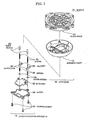
- FIG. 1 shows a mirror 18 according to one exemplary embodiment of the present invention.
- various components other than principal portions necessary to detect an angle of a specular surface are not illustrated for the sake of clarity. It is to be understood the mirror 18 also includes other components that are not illustrated, such as a mirror body and a specular surface.
- the mirror 18 is an exterior mirror for an automobile, which includes an actuator 16 and an angle detection apparatus 14.
- the actuator 16 includes a housing front 12 and a plate pivot 10.
- the housing front 12 is a housing for holding the plate pivot 10.
- the plate pivot 10 is one example of an interlocking member adapted to rotate about an axis parallel with the specular surface of the mirror 18 so as to tilt the specular surface.
- the plate pivot 10 is adapted to change its orientation together with the specular surface so as to orient in a direction in which the specular surface is orienting.
- the actuator 16 is adapted to rotate the specular surface using the plate pivot 10 to change the orientation of the specular surface.
- the angle detection apparatus 14 includes slide blocks 20, springs 22, guide cases 24, magnets 26, springs 28, cover springs 30, a PC board 32, a cover 34, and tapping screws 36.
- two sets of the components 20, 22, 24, 26, 28 and 30 are provided to detect two kinds of angular displacement of the specular surface which are caused by rotation of the specular surface about the vertical and horizontal axes, respectively, though the number of these components may be configured otherwise.
- the slide blocks 20 are stressed by the springs 22, respectively, toward the back side of the plate pivot 10, while the housing front 12 is disposed between the slide blocks 20 and the back side of the plate pivot 10. Rotation of the plate pivot 10 causes the slide blocks 20 to move in a direction of movement substantially perpendicular to the specular surface by an amount proportional to an amount of the rotation of the plate pivot 10.
- the slide blocks 20 may be inserted in holes provided in the housing front 12 so that tips of the slide blocks 20 protruding through the holes of the housing front 12 are brought into contact with and pressed on the plate pivot 10.
- Each guide case 24 serves as a casing for accommodating magnet 26 corresponding thereto to hold the magnet 26 between spring 22 and spring 28 corresponding thereto.
- Magnet 26 is one example of a movable member, and a permanent magnet is employed therefor in the present embodiment.
- Spring 28 is one example of a second elastic member, and adapted to stress guide case 24 corresponding thereto to thereby stress the magnet 26 accommodated in the guide case 24 toward the spring 22.
- Cover spring 30 is provided to support an end of each spring 28 farther from the magnet 26.
- the movement of the slide block 20 in a direction substantially perpendicular to the specular surface causes the magnet 26 to move in the same direction as the direction of the movement of the slide block 20 by an amount proportional to and smaller than the amount of the movement of the slide block 20.
- the angle detection apparatus 14 may alternatively be designed to include any other kinds of elastic members such as leaf springs, etc., instead of helical springs 22, 28 as shown in FIG. 1, as first and/or second elastic members.
- the PC board 32 is a circuit board on which peripheral circuits such as angle detection circuit are mounted.
- the PC board 32 is opposed to the plate pivot 10 with the slide blocks 20, springs 22, guide cases 24, magnets 26, springs 28 and cover springs 30 disposed between the PC board 32 and the plate pivot 10.
- the cover 34 are designed to fit to the housing front 12 to form a cover for accommodating the slide blocks 20, springs 22, guide cases 24, magnets 26, springs 28, cover springs 30 and PC board 32.
- the tapping screws 36 are used to fix the cover 34 to the housing front 12.
- the angle of the specular surface can be appropriately detected; the angle detection apparatus 14 can be arranged at any desired location on a vertical or horizontal line with respect to the mirror 18; the increased flexibility in layout design facilitates the utilization of spaces around the actuator 16 or that which would otherwise be occupied by the actuator 16, thus improves the space efficiency; an actuator unit composed of the angle detection apparatus 14 and the actuator 16 can be provided in reduced size; and the angle detection apparatus 14 can be retrofitted to the actuator 16, so that a general-purpose actuator provided off the shelf in the market can be used as the actuator 16.
- the cost of the mirror 18 can be reduced.
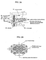
- FIGS. 2A and 2B are diagrams showing an exemplary operation of the mirror 18.
- FIG. 2A illustrates the angle detection apparatus 14 in operation.
- the PC board 32 is provided with an angle detection circuit 200 including a magnetism sensing element 202 and an operational amplifier 204.
- the magnetism sensing element 202 is one example of the moving amount detection unit according to the present invention.
- the magnetism sensing element 202 is a Hall element or Hall sensor of the lead type, and mounted on the PC board 32.
- the plate pivot 10 is adapted to rotate in a range of ⁇ 14 degrees to drive the specular surface of the mirror 18.
- the slide block 20 moves linearly in the range of ⁇ 6 mm.
- the slide block 20 converts rotational motion into rectilinear motion.
- the spring 28 has a spring constant different from that of the spring 22. Therefore, when the slide block 20 moves, the magnet 26 sandwiched between the spring 22 and the spring 28 moves in the direction in which the slide block 20 moves, and by an amount of movement different from the amount by which the slide block 20 moves.
- the slide block 20 moves linearly in the range of ⁇ 6mm, and the magnet 26 moves linearly in the range of ⁇ 2mm, accordingly.
- the movement of the magnet 26 can be restricted within a smaller range, which thus makes it possible to use the magnet 26 smaller in size than that which would otherwise be required if the same maximum distance of movement of the slide block 20 is desired.
- the maximum distance of movement of the slide block 20 is the distance of movement covered by the slide block 20 corresponding to the permissible range of rotation of the specular surface.
- the neutral position of the magnet 26 can be adjusted as desired to a neutral position corresponding to the neutral position of the magnetism sensing element 202.
- This obviates the necessity for positioning the magnetism sensing element near the magnet 26 by making use of a harness, a flexible board, or the like.
- the workability of mounting the magnetism sensing element 202 is improved, so that the cost of the mirror 18 can be reduced.
- FIG. 2B illustrates the plate pivot 10 in operation.
- the plate pivot 10 rotates about axes, namely, the vertical axis of rotation and the horizontal axis of rotation, respectively.
- a plurality of slide blocks 20 are each located at any point on the vertical axis of rotation or on the horizontal axis of rotation.
- the magnets 26, the magnetism sensing elements 202 and other components corresponding to the respective slide blocks 20 are located in the positions corresponding to the positions in which the corresponding slide blocks 20 are located.
- the slide blocks 20 can be located in any positions on the vertical axis of rotation or on the horizontal axis of rotation. Therefore, the angle detection apparatus 14 can be arranged in the spaces around the actuator 16 or that which would otherwise be occupied by the actuator 16. As a result, according to the present embodiment, spaces within the mirror 18 can be utilized effectively.
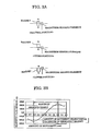
- FIGS. 3A and 3B are diagrams for explaining a relationship between the size of a magnet and the operation of a magnetism sensing element.
- the magnetism sensing element comprised of a Hall element according to the present invention detects magnetic flux density for example as shown in FIG. 3B.
- the balance of loads of the spring 22 and the spring 28 is adjusted to convert the motion of the spring 22 moving in the range of ⁇ 6mm to a smaller motion of the magnet 26 moving in the range of ⁇ 2mm. Therefore, the amount of movement to be detected becomes smaller so that the magnet 26 to be used can be selected among smaller ones.
- FIG. 4A is an exemplified schematic circuit diagram of the angle detection apparatus 200.
- the angle detection apparatus 200 includes a magnetism sensing element 202, a plurality of temperature-compensating elements 206, and an operational amplifier 204.
- the magnetism sensing element 202 is a Hall element, and adapted to output a Hall voltage in accordance with magnetism detected, based upon a current supplied from a constant-current circuit comprised of a voltage follower IC1-1, a transistor Q1 and other components.
- the magnetism sensing element 202 outputs the Hall voltage as a differential between a first voltage output terminal connected through a resistor R6 to a temperature-compensating element 206 (R8) and a second voltage output terminal connected through a resistor R7 to a temperature-compensating element 206 (R9).
- the plurality of temperature-compensating elements 206 are thermisters or thermal resistors adapted to decrease its resistance in accordance with increase in temperature.
- the plurality of temperature-compensating elements 206 are connected to the first and second voltage output terminals of the magnetism sensing elements 202, respectively, to thereby compensate temperature characteristics of the magnet 26 and magnetism sensing element 202.
- the operational amplifier 204 amplifies a Hall voltage received through the plurality of temperature-compensating elements 206 from the magnetism sensor 202.
- the temperature-compensating elements 206 to be used may be adapted to increase its resistance in accordance with increase in temperature.
- the present invention is suitable for an automotive exterior mirror, for example.
- FIG. 1 A first figure.
- MAGNET MAGNETISM SENSING ELEMENT ⁇ NEUTRAL POSITION> MAGNET MAGNETISM SENSING ELEMENT ⁇ UPPER POSITION> MAGNET MAGNETISM SENSING ELEMENT ⁇ LOWER POSITION>
- MAGNETIC FLUX DENSITY G
- AMOUNT OF MOVEMENT mm
- FIG. 4A is a diagrammatic representation of FIG. 4A
Landscapes
- Engineering & Computer Science (AREA)
- Multimedia (AREA)
- Mechanical Engineering (AREA)
- Transmission And Conversion Of Sensor Element Output (AREA)
- Measurement Of Length, Angles, Or The Like Using Electric Or Magnetic Means (AREA)
- Rear-View Mirror Devices That Are Mounted On The Exterior Of The Vehicle (AREA)
Applications Claiming Priority (1)
| Application Number | Priority Date | Filing Date | Title |
|---|---|---|---|
| JP2004229745A JP4303657B2 (ja) | 2004-08-05 | 2004-08-05 | ミラー及び角度検出装置 |
Publications (2)
| Publication Number | Publication Date |
|---|---|
| EP1632394A2 true EP1632394A2 (de) | 2006-03-08 |
| EP1632394A3 EP1632394A3 (de) | 2007-09-05 |
Family
ID=35506322
Family Applications (1)
| Application Number | Title | Priority Date | Filing Date |
|---|---|---|---|
| EP05016679A Withdrawn EP1632394A3 (de) | 2004-08-05 | 2005-08-01 | Spiegel und Winkelmessvorrichtung |
Country Status (3)
| Country | Link |
|---|---|
| US (1) | US7270432B2 (de) |
| EP (1) | EP1632394A3 (de) |
| JP (1) | JP4303657B2 (de) |
Families Citing this family (4)
| Publication number | Priority date | Publication date | Assignee | Title |
|---|---|---|---|---|
| JP2006096130A (ja) * | 2004-09-29 | 2006-04-13 | Murakami Corp | ミラー及び角度検出装置 |
| EP1925962A1 (de) * | 2006-11-21 | 2008-05-28 | Swiss Medical Technology GmbH | Stereo-Video-Mikroskopsystem |
| KR20090051859A (ko) * | 2007-11-20 | 2009-05-25 | 삼성전기주식회사 | 스캐너 및 이를 구비하는 디스플레이 장치 |
| CN104512342B (zh) * | 2014-12-29 | 2017-06-30 | 余姚市利佛德汽车零部件有限公司 | 汽车后视镜 |
Citations (1)
| Publication number | Priority date | Publication date | Assignee | Title |
|---|---|---|---|---|
| JPH03112441U (de) | 1990-03-02 | 1991-11-18 |
Family Cites Families (12)
| Publication number | Priority date | Publication date | Assignee | Title |
|---|---|---|---|---|
| US5064274A (en) * | 1987-08-26 | 1991-11-12 | Siegel-Robert, Inc. | Automatic automobile rear view mirror assembly |
| JPH03112441A (ja) | 1989-09-26 | 1991-05-14 | Mitsui Toatsu Chem Inc | 浅漬けの包装体 |
| JP3396018B2 (ja) * | 1997-03-25 | 2003-04-14 | 株式会社村上開明堂 | ミラー位置検出装置 |
| US6412960B1 (en) * | 1999-09-14 | 2002-07-02 | Kabushiki Kaisha Tokai-Rika-Denki-Seisakusho | Mirror surface angle adjusting device and mirror surface angle detector for a vehicle |
| DE19952812C1 (de) * | 1999-11-02 | 2001-08-16 | Hohe Gmbh & Co Kg | Außenrückspiegel mit Positionssensor |
| US6478436B1 (en) * | 2001-05-22 | 2002-11-12 | Eaton Corporation | Sensing mirror position in a powered mirror positioning system |
| JP4075543B2 (ja) * | 2002-09-11 | 2008-04-16 | 市光工業株式会社 | ミラー駆動装置 |
| JP4012460B2 (ja) * | 2002-11-28 | 2007-11-21 | 株式会社東海理化電機製作所 | 車両用アウタミラー装置 |
| JP4217187B2 (ja) * | 2004-04-07 | 2009-01-28 | 株式会社村上開明堂 | ミラー位置検出装置 |
| JP2006044511A (ja) * | 2004-08-05 | 2006-02-16 | Murakami Corp | ミラー及び角度検出装置 |
| JP2006096130A (ja) * | 2004-09-29 | 2006-04-13 | Murakami Corp | ミラー及び角度検出装置 |
| JP2006096147A (ja) * | 2004-09-29 | 2006-04-13 | Murakami Corp | ミラー及び角度検出装置 |
-
2004
- 2004-08-05 JP JP2004229745A patent/JP4303657B2/ja not_active Expired - Fee Related
-
2005
- 2005-08-01 EP EP05016679A patent/EP1632394A3/de not_active Withdrawn
- 2005-08-03 US US11/195,761 patent/US7270432B2/en not_active Expired - Fee Related
Patent Citations (1)
| Publication number | Priority date | Publication date | Assignee | Title |
|---|---|---|---|---|
| JPH03112441U (de) | 1990-03-02 | 1991-11-18 |
Also Published As
| Publication number | Publication date |
|---|---|
| US7270432B2 (en) | 2007-09-18 |
| EP1632394A3 (de) | 2007-09-05 |
| US20060029376A1 (en) | 2006-02-09 |
| JP2006044510A (ja) | 2006-02-16 |
| JP4303657B2 (ja) | 2009-07-29 |
Similar Documents
| Publication | Publication Date | Title |
|---|---|---|
| CN109889711B (zh) | 摄像模组 | |
| US20190339495A1 (en) | Camera system | |
| CN102047164B (zh) | 透镜驱动装置 | |
| US20020176713A1 (en) | Image-capturing device | |
| CN113966606B (zh) | 相机装置 | |
| CN108020901B (zh) | 透镜驱动装置 | |
| EP1632394A2 (de) | Spiegel und Winkelmessvorrichtung | |
| EP4228240B1 (de) | Kameravorrichtung und optisches instrument | |
| EP1630530B1 (de) | Flüssigkeitsstandsdetektor | |
| US7113697B2 (en) | Displacement detection device and lens barrel | |
| US7585082B2 (en) | Mirror and angle detection device | |
| CN116859545B (zh) | 镜头驱动装置、相机和电子设备 | |
| JP2006096147A (ja) | ミラー及び角度検出装置 | |
| US11789339B2 (en) | Camera device and electronic apparatus | |
| CN115586683B (zh) | 照相机装置以及电子设备 | |
| CN214896138U (zh) | 照相机装置以及电子设备 | |
| EP1632395A2 (de) | Spiegel und Winkelmessvorrichtung | |
| CN209858822U (zh) | 透镜驱动装置、照相装置以及电子设备 | |
| KR101204892B1 (ko) | 상 흔들림 보정 장치 | |
| JP3230102B2 (ja) | 摺動抵抗式リニア特性センサ | |
| CN223051504U (zh) | 用于控制电气设备运行的非接触控制组件及电气开关 | |
| CN111830658A (zh) | 透镜驱动装置、照相装置以及电子设备 | |
| KR101170746B1 (ko) | 상 흔들림 보정 장치 | |
| CN112817195B (zh) | 透镜驱动装置、照相机装置以及电子设备 | |
| US20110116778A1 (en) | Zoom switch assembly, image photographing apparatus having the same, and method of controlling zoom lens |
Legal Events
| Date | Code | Title | Description |
|---|---|---|---|
| PUAI | Public reference made under article 153(3) epc to a published international application that has entered the european phase |
Free format text: ORIGINAL CODE: 0009012 |
|
| AK | Designated contracting states |
Kind code of ref document: A2 Designated state(s): AT BE BG CH CY CZ DE DK EE ES FI FR GB GR HU IE IS IT LI LT LU LV MC NL PL PT RO SE SI SK TR |
|
| AX | Request for extension of the european patent |
Extension state: AL BA HR MK YU |
|
| PUAL | Search report despatched |
Free format text: ORIGINAL CODE: 0009013 |
|
| AK | Designated contracting states |
Kind code of ref document: A3 Designated state(s): AT BE BG CH CY CZ DE DK EE ES FI FR GB GR HU IE IS IT LI LT LU LV MC NL PL PT RO SE SI SK TR |
|
| AX | Request for extension of the european patent |
Extension state: AL BA HR MK YU |
|
| AKX | Designation fees paid | ||
| STAA | Information on the status of an ep patent application or granted ep patent |
Free format text: STATUS: THE APPLICATION IS DEEMED TO BE WITHDRAWN |
|
| 18D | Application deemed to be withdrawn |
Effective date: 20080301 |
|
| REG | Reference to a national code |
Ref country code: DE Ref legal event code: 8566 |