EP1633031A2 - Drehende elektrische Maschine - Google Patents
Drehende elektrische Maschine Download PDFInfo
- Publication number
- EP1633031A2 EP1633031A2 EP05016434A EP05016434A EP1633031A2 EP 1633031 A2 EP1633031 A2 EP 1633031A2 EP 05016434 A EP05016434 A EP 05016434A EP 05016434 A EP05016434 A EP 05016434A EP 1633031 A2 EP1633031 A2 EP 1633031A2
- Authority
- EP
- European Patent Office
- Prior art keywords
- stator core
- steel sheets
- cut
- stacked
- rotating machine
- Prior art date
- Legal status (The legal status is an assumption and is not a legal conclusion. Google has not performed a legal analysis and makes no representation as to the accuracy of the status listed.)
- Granted
Links
- 229910000831 Steel Inorganic materials 0.000 claims abstract description 63
- 239000010959 steel Substances 0.000 claims abstract description 63
- 229910000976 Electrical steel Inorganic materials 0.000 claims abstract description 32
- 238000005096 rolling process Methods 0.000 claims description 28
- 230000004907 flux Effects 0.000 description 27
- XEEYBQQBJWHFJM-UHFFFAOYSA-N Iron Chemical compound [Fe] XEEYBQQBJWHFJM-UHFFFAOYSA-N 0.000 description 17
- 238000013021 overheating Methods 0.000 description 10
- 229910052742 iron Inorganic materials 0.000 description 8
- 230000020169 heat generation Effects 0.000 description 6
- 230000005415 magnetization Effects 0.000 description 4
- 238000010586 diagram Methods 0.000 description 3
- 238000001816 cooling Methods 0.000 description 1
- 230000000694 effects Effects 0.000 description 1
- 238000010438 heat treatment Methods 0.000 description 1
- 238000009413 insulation Methods 0.000 description 1
- 230000002093 peripheral effect Effects 0.000 description 1
- 229920001296 polysiloxane Polymers 0.000 description 1
Images


Classifications
-
- H—ELECTRICITY
- H02—GENERATION; CONVERSION OR DISTRIBUTION OF ELECTRIC POWER
- H02K—DYNAMO-ELECTRIC MACHINES
- H02K1/00—Details of the magnetic circuit
- H02K1/06—Details of the magnetic circuit characterised by the shape, form or construction
- H02K1/12—Stationary parts of the magnetic circuit
- H02K1/16—Stator cores with slots for windings
-
- H—ELECTRICITY
- H02—GENERATION; CONVERSION OR DISTRIBUTION OF ELECTRIC POWER
- H02K—DYNAMO-ELECTRIC MACHINES
- H02K1/00—Details of the magnetic circuit
- H02K1/02—Details of the magnetic circuit characterised by the magnetic material
Definitions
- the present invention relates to an electrical rotating machine, and more specifically, to an improved electrical rotating machine in which a local rise of temperature in a stator core is reduced.
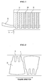
- Electrical steel sheets are die-cut into substantially sector shapes as shown in FIG. 2 and arranged in a circumferential direction to form circular sheets which are stacked in an axial direction to form a stator core of a large size electrical rotating machine.
- a sheet segment in a substantially sector shape includes teeth 1 between which there is provided a slot 3 where a coil is inserted, and a yoke 2 which forms a peripheral part of the sheet segment.
- electrical steel sheets used for a stator core in an electrical rotating machine are non-grain oriented steel sheets in which a direction of easy magnetization is random and grain oriented steel sheets in which a direction of easy magnetization is aligned with a rolling direction of a steel band.
- grain oriented steel sheets are used as steel sheets for an iron core and circumferential directions of segment sheets are aligned with a rolling direction of a steel band as shown in FIG 2 so that magnetic flux in a circumferential direction of a yoke 2 passes in a direction of easy magnetization.
- circumferential directions of sheet segments of non-grain oriented steel sheets are also aligned with a rolling direction of a steel band since magnetic flux tends to pass more easily in the rolling direction of the steel band.
- a slit 8 is provided to each of teeth 1 as shown in FIG.4 to narrow a flow path of eddy current in each of the teeth 1 and reduce eddy current loss caused by axial magnetic flux.
- blocks 4 in each of end regions of a stator core are formed in a stepped taper shape as shown in FIG. 5 to prevent magnetic flux from locally concentrating.
- stator core of an electrical rotating machine only several sheet segments of each of end regions of a stator core of an electrical rotating machine are die-cut from non-grain oriented steel sheets, or from electrical steel sheets in such a manner that a radial direction is aligned with a rolling direction of the electrical steel sheets, and then stacked to form the stator core allowing magnetic flux to pass easily in teeth to reduce heat generation caused by magnetic flux in a radial direction and prevent local overheating in teeth.
- a stator core according to the present invention can provide a highly reliable electrical rotating machine by preventing local overheating in teeth in end regions.
- an electrical rotating machine including a stator core which is formed of substantially sector-shaped sheet segments die-cut from electrical steel sheets and arranged in a circumferential direction of the stator core to form circular sheets which are stacked in an axial direction of the stator core.
- end regions of the stator core are formed of stacked sheet segments die-cut from non-grain oriented steel sheets and the other region of the stator core is formed of stacked sheet segments die-cut from grain oriented steel sheets.
- One or more slits may be formed in each of teeth in end regions of the stator core.
- an electrical rotating machine including a stator core which is formed of substantially sector-shaped sheet segments die-cut from electrical steel sheets and arranged in a circumferential direction of the stator core to form circular sheets which are stacked in an axial direction of the stator core.
- end regions of the stator core are formed of stacked sheet segments die-cut from electrical steel sheets in such a manner that a radial direction of each sheet segment is aligned with a rolling direction of the electrical steel sheets.
- One or more slits may be formed in each of teeth in end regions of the stator core.
- An electrical rotating machine includes a stator core which is formed of substantially sector-shaped sheet segments die-cut from electrical steel sheets and arranged in a circumferential direction of the stator core to form circular sheets which are stacked in an axial direction of the stator core.
- One or more slits are formed in each of teeth in end regions of the stator core.
- the end regions of the stator core are formed of stacked sheet segments die-cut from non-grain oriented steel sheets, and the other region of the stator core is formed of stacked sheet segments die-cut from grain oriented steel sheets.
- An electrical rotating machine includes a stator core which is formed of substantially sector-shaped sheet segments die-cut from electrical steel sheets and arranged in a circumferential direction of the stator core to form circular sheets which are stacked in an axial direction of the stator core.
- One or more slits are formed in each of teeth in end regions of the stator core.
- the end regions of the stator core are formed of stacked sheet segments die-cut from electrical steel sheets in such a manner that a radial direction of each sheet segment is aligned with a rolling direction of the electrical steel sheets.
- An electrical rotating machine includes a stator core which is formed of substantially sector-shaped sheet segments die-cut from electrical steel sheets and arranged in a circumferential direction of the stator core to form circular sheets which are stacked in an axial direction of the stator core.
- a stepped tapered portion is formed in each of end regions of the stator core.
- the end regions of the stator core are formed of stacked sheet segments die-cut from non-grain oriented steel sheets, and the other region of the stator core is formed of stacked sheet segments die-cut from grain oriented steel sheets.
- One or more slits may be formed in each of teeth of the sheet segments die-cut from the non-grain oriented steel sheet.
- An electrical rotating machine includes a stator core which is formed of substantially sector-shaped sheet segments die-cut from electrical steel sheets and arranged in a circumferential direction of the stator core to form circular sheets which are stacked in an axial direction of the stator core.
- a stepped tapered portion is formed in each of end regions of the stator core.
- the end regions of the stator core are formed of stacked sheet segments die-cut from electrical steel sheets in such a manner that a radial direction of each sheet segment is aligned with a rolling direction of the electrical steel sheets.
- One or more slits may be formed in each of teeth of the stacked sheet segments die-cut from the electrical steel sheets in such a manner that the radial direction of each sheet segment is aligned with the rolling direction.
- FIG. 1 illustrates a first embodiment of an electrical rotating machine according to the present invention.
- only two blocks 11 in each of end regions of a stator core (that is, four blocks in total on the both ends) are comprised of stacked non-grain oriented steel sheets, while blocks 10 in the other region of the stator core are comprised of stacked grain oriented steel sheets.
- non-grain oriented steel sheets in which it is easier for magnetic flux to pass compared with in a direction perpendicular to a rolling direction of grain oriented steel sheets, are used for the two blocks in each of the end regions of the stator core to reduce heat generation in the teeth 1 and prevent local overheating in the end regions of the stator core.
- the sheet segments may be die-cut from non-grain oriented steel sheets in a direction shown in FIG. 2.
- FIG. 7 illustrates a second embodiment of an electrical rotating machine according to the present invention.
- only two blocks 12 in each of end regions of a stator core that is, four blocks in total on the both ends
- a block 10 of grain oriented steel sheets comprised of sheet segments whose circumferential directions are aligned with a rolling direction of the steel sheet as shown in FIG. 2, it is difficult for magnetic flux to pass in teeth 1 while it is easy for magnetic flux to pass in a yoke 2.
- teeth of the sheet segments of the two blocks in each of the end regions of the stator core are aligned with a rolling direction in which magnetic flux easily passes to reduce heat generation in the teeth 1 and prevent local overheating in the end regions of the stator core.
- FIG. 8 illustrates a third embodiment of an electrical rotating machine according to the present invention.
- only three blocks 11 in each of end regions of a stator core having a stepped taper formed at its end are comprised of stacked non-grain oriented steel sheets, while blocks 10 in the other region of the stator core are comprised of stacked grain oriented steel sheets.
- non-grain oriented steel sheets in which it is easier for magnetic flux to pass compared with in a direction perpendicular to a rolling direction of grain oriented steel sheets, are used for the blocks in the end regions, having the stepped taper formed at its end, to reduce heat generation in teeth 1 and prevent local overheating in the end regions of the stator core.
Landscapes
- Engineering & Computer Science (AREA)
- Power Engineering (AREA)
- Iron Core Of Rotating Electric Machines (AREA)
Applications Claiming Priority (1)
| Application Number | Priority Date | Filing Date | Title |
|---|---|---|---|
| JP2004253711A JP4548049B2 (ja) | 2004-09-01 | 2004-09-01 | 回転電機 |
Publications (3)
| Publication Number | Publication Date |
|---|---|
| EP1633031A2 true EP1633031A2 (de) | 2006-03-08 |
| EP1633031A3 EP1633031A3 (de) | 2010-08-04 |
| EP1633031B1 EP1633031B1 (de) | 2017-09-20 |
Family
ID=34937923
Family Applications (1)
| Application Number | Title | Priority Date | Filing Date |
|---|---|---|---|
| EP05016434.2A Ceased EP1633031B1 (de) | 2004-09-01 | 2005-07-28 | Drehende elektrische Maschine |
Country Status (4)
| Country | Link |
|---|---|
| US (1) | US8760028B2 (de) |
| EP (1) | EP1633031B1 (de) |
| JP (1) | JP4548049B2 (de) |
| CN (1) | CN100414813C (de) |
Cited By (1)
| Publication number | Priority date | Publication date | Assignee | Title |
|---|---|---|---|---|
| EP2112742A2 (de) | 2008-04-25 | 2009-10-28 | Hitachi, Ltd. | Elektrische Drehmaschine |
Families Citing this family (21)
| Publication number | Priority date | Publication date | Assignee | Title |
|---|---|---|---|---|
| US7620392B1 (en) | 2006-02-27 | 2009-11-17 | Good Technology, Inc. | Method and system for distributing and updating software in wireless devices |
| CN101588092B (zh) * | 2008-04-25 | 2012-10-10 | 株式会社日立制作所 | 旋转电机 |
| JP5476699B2 (ja) * | 2008-10-06 | 2014-04-23 | 新日鐵住金株式会社 | 発電機用固定子 |
| BE1019030A5 (nl) | 2009-08-03 | 2012-01-10 | Atlas Copco Airpower Nv | Turbocompressorsysteem. |
| US10594172B2 (en) | 2015-11-12 | 2020-03-17 | Hamilton Sundstrand Corporation | Electric component including custom metal grain orientation |
| JP2017158344A (ja) * | 2016-03-03 | 2017-09-07 | 日産自動車株式会社 | 回転電機 |
| EA202192063A1 (ru) | 2018-12-17 | 2021-11-24 | Ниппон Стил Корпорейшн | Шихтованный сердечник и электродвигатель |
| EA202192064A1 (ru) * | 2018-12-17 | 2021-11-24 | Ниппон Стил Корпорейшн | Шихтованный сердечник и электродвигатель |
| JP7418350B2 (ja) | 2018-12-17 | 2024-01-19 | 日本製鉄株式会社 | ステータ用接着積層コアおよび回転電機 |
| JP7576981B2 (ja) | 2018-12-17 | 2024-11-01 | 日本製鉄株式会社 | 積層コアおよび回転電機 |
| EP3902121B1 (de) | 2018-12-17 | 2025-08-13 | Nippon Steel Corporation | Adhäsiv laminierter kern für stator und elektromotor |
| SG11202108923TA (en) | 2018-12-17 | 2021-09-29 | Nippon Steel Corp | Laminated core, laminated core manufacturing method, and electric motor |
| CA3131671A1 (en) | 2018-12-17 | 2020-06-25 | Nippon Steel Corporation | Adhesively-laminated core for stator, method of manufacturing the same, and electric motor |
| WO2020129928A1 (ja) | 2018-12-17 | 2020-06-25 | 日本製鉄株式会社 | 積層コアおよび回転電機 |
| JP6863525B2 (ja) | 2018-12-17 | 2021-04-21 | 日本製鉄株式会社 | 積層コアおよび回転電機 |
| CA3131675C (en) | 2018-12-17 | 2024-04-16 | Nippon Steel Corporation | Adhesively-laminated core for stator, method of manufacturing same, and electric motor |
| WO2020129923A1 (ja) | 2018-12-17 | 2020-06-25 | 日本製鉄株式会社 | 積層コアおよび回転電機 |
| JP6940007B2 (ja) * | 2018-12-17 | 2021-09-22 | 日本製鉄株式会社 | 積層コア、コアブロック、回転電機およびコアブロックの製造方法 |
| RS65460B1 (sr) | 2018-12-17 | 2024-05-31 | Nippon Steel Corp | Laminirano jezgro i električni motor |
| CN117321895A (zh) * | 2021-06-01 | 2023-12-29 | 三菱电机株式会社 | 旋转电机的定子铁心、旋转电机的定子、旋转电机、旋转电机的定子铁心的制造方法及旋转电机的制造方法 |
| DE102022132790A1 (de) | 2022-12-09 | 2024-06-20 | Dr. Ing. H.C. F. Porsche Aktiengesellschaft | Elektrische Maschine mit einem Blechpaket |
Family Cites Families (27)
| Publication number | Priority date | Publication date | Assignee | Title |
|---|---|---|---|---|
| US1367298A (en) * | 1917-02-08 | 1921-02-01 | Burke Electric Company | Alternating-current motor and generator |
| US2774000A (en) * | 1955-06-29 | 1956-12-11 | Westinghouse Electric Corp | Oriented-steel stator-cores |
| FR1588684A (de) * | 1968-10-01 | 1970-04-17 | ||
| US3812392A (en) * | 1973-03-09 | 1974-05-21 | Gen Electric | Composite armature core for dynamoelectric machine |
| JPS51125508U (de) * | 1975-04-02 | 1976-10-12 | ||
| JPS5219202A (en) * | 1975-08-06 | 1977-02-14 | Hitachi Ltd | Stator cores for rotary electric machines |
| JPS607892B2 (ja) * | 1977-08-23 | 1985-02-27 | 株式会社東芝 | 回転電機の固定子鉄心 |
| DE3006207C2 (de) * | 1980-02-15 | 1982-10-21 | Siemens AG, 1000 Berlin und 8000 München | Elektrische Maschine mit einem Ständerblechpaket aus kornorientierten Blechen |
| JPS57160360A (en) * | 1981-03-27 | 1982-10-02 | Hitachi Ltd | Superconductive generator |
| JPS5863046A (ja) * | 1981-10-09 | 1983-04-14 | Hitachi Ltd | 回転電機の固定子鉄心 |
| JPS6162334A (ja) * | 1984-08-30 | 1986-03-31 | Mitsubishi Electric Corp | 回転電機 |
| US4609840A (en) * | 1984-11-05 | 1986-09-02 | General Electric Company | Baffle for improving coolant gas flow distribution in the gap region of a gas cooled dynamoelectric machine |
| JPS63217940A (ja) | 1987-03-06 | 1988-09-12 | Toshiba Corp | 回転電機の固定子鉄心 |
| JPS63277438A (ja) * | 1987-03-11 | 1988-11-15 | Isuzu Motors Ltd | 高速回転電機の回転子構造 |
| JP2862568B2 (ja) * | 1989-06-28 | 1999-03-03 | 株式会社東芝 | 電動機 |
| JPH05184088A (ja) * | 1992-01-07 | 1993-07-23 | Nippondenso Co Ltd | 車両用交流発電機 |
| JPH08193894A (ja) * | 1995-01-17 | 1996-07-30 | Yaskawa Electric Corp | 歪検出器 |
| JP2000050539A (ja) | 1998-07-28 | 2000-02-18 | Toshiba Corp | 回転電機の固定子鉄心、固定子鉄心用鋼板部品、固定子鉄心の製造方法および固定子鉄心用鋼板部品の製造方法 |
| JP2000278891A (ja) * | 1999-03-26 | 2000-10-06 | Nissan Motor Co Ltd | 電動機のステータコア及びステータの製造方法 |
| FR2806851B1 (fr) * | 2000-03-21 | 2003-01-17 | Valeo Equip Electr Moteur | Machine electrique tournante dont le stator comporte un empilage axial de plaques de tole de permeabilites magnetiques differentes |
| US7887645B1 (en) * | 2001-05-02 | 2011-02-15 | Ak Steel Properties, Inc. | High permeability grain oriented electrical steel |
| US6525444B2 (en) * | 2001-05-16 | 2003-02-25 | General Electric Company | Apparatus and method utilizing amorphous metal laminates in an electric generator |
| JP2003274581A (ja) * | 2002-03-12 | 2003-09-26 | Nippon Steel Corp | 同期機 |
| JP2003319575A (ja) * | 2002-04-17 | 2003-11-07 | Nippon Steel Corp | 同期機のステータ鉄心 |
| JP4154957B2 (ja) * | 2002-08-27 | 2008-09-24 | 松下電器産業株式会社 | マグネット内装型ロータおよびそれを用いたブラシレスモータ |
| US7057324B2 (en) * | 2002-12-19 | 2006-06-06 | General Electric Company | Silicon steel punching orientation modifications to lower eddy current losses at the stator core end of dynamoelectric machines |
| JP4323940B2 (ja) * | 2002-12-20 | 2009-09-02 | 新日本製鐵株式会社 | 励磁機、界磁機およびそれを用いた同期機 |
-
2004
- 2004-09-01 JP JP2004253711A patent/JP4548049B2/ja not_active Expired - Fee Related
-
2005
- 2005-07-28 EP EP05016434.2A patent/EP1633031B1/de not_active Ceased
- 2005-07-29 US US11/194,919 patent/US8760028B2/en not_active Expired - Fee Related
- 2005-08-03 CN CNB2005100890540A patent/CN100414813C/zh not_active Expired - Fee Related
Cited By (7)
| Publication number | Priority date | Publication date | Assignee | Title |
|---|---|---|---|---|
| EP2112742A2 (de) | 2008-04-25 | 2009-10-28 | Hitachi, Ltd. | Elektrische Drehmaschine |
| EP2112742A3 (de) * | 2008-04-25 | 2011-06-15 | Hitachi, Ltd. | Elektrische Drehmaschine |
| EP2362523A1 (de) * | 2008-04-25 | 2011-08-31 | Hitachi, Ltd. | Elektrische Drehmaschine |
| EP2362524A1 (de) * | 2008-04-25 | 2011-08-31 | Hitachi, Ltd. | Elektrische Drehmaschine |
| US8174156B2 (en) | 2008-04-25 | 2012-05-08 | Hitachi, Ltd. | Rotating electrical machine with different lamination steel kinds and spacing |
| US8304953B2 (en) | 2008-04-25 | 2012-11-06 | Hitachi, Ltd. | Rotating electrical machine |
| US8624462B2 (en) | 2008-04-25 | 2014-01-07 | Hitachi, Ltd. | Rotating electrical machine |
Also Published As
| Publication number | Publication date |
|---|---|
| EP1633031A3 (de) | 2010-08-04 |
| CN1744407A (zh) | 2006-03-08 |
| EP1633031B1 (de) | 2017-09-20 |
| US20060043820A1 (en) | 2006-03-02 |
| JP2006074880A (ja) | 2006-03-16 |
| US8760028B2 (en) | 2014-06-24 |
| CN100414813C (zh) | 2008-08-27 |
| JP4548049B2 (ja) | 2010-09-22 |
Similar Documents
| Publication | Publication Date | Title |
|---|---|---|
| EP1633031B1 (de) | Drehende elektrische Maschine | |
| JP4528865B2 (ja) | 回転電機 | |
| JP4884418B2 (ja) | 分割固定子鉄心の製造方法 | |
| US7705503B2 (en) | Rotating electrical machine | |
| JP5130321B2 (ja) | 回転電機 | |
| US20180198334A1 (en) | Rotary electric-machine rotor | |
| US10389194B2 (en) | Permanent magnet electrical rotating machine with protection members arranged between permanent magnets and rotor cores | |
| US8138653B2 (en) | Rotating electric machine | |
| JP2010017003A (ja) | 回転電機のステータコア | |
| JP5258944B2 (ja) | 電動機及び分割固定子鉄心の製造方法 | |
| JP2012235645A (ja) | 永久磁石式回転電機 | |
| JP6640685B2 (ja) | 回転電機およびそれを用いた駆動システム | |
| JP2013172568A (ja) | 回転電機 | |
| JP2019161828A (ja) | 回転電機 | |
| US20150194851A1 (en) | Permanent magnet rotating electrical machine | |
| JP2005287262A (ja) | ロータおよびモータ | |
| US20220103033A1 (en) | Rotary electric machine | |
| JP2016086602A (ja) | 回転電機 | |
| JP7085853B2 (ja) | 回転電機、回転電機の製造方法、および送風機 | |
| JP3734435B2 (ja) | 回転電機の相リード | |
| US11682934B2 (en) | Rotary electric machine with rotor having permanent magnets with ratios of total surface area and a stator with tooth having coils with offset from flange portions | |
| JP2000050572A (ja) | 誘導電動機 | |
| JPH0946937A (ja) | 電動機の固定子 | |
| JP2011244688A (ja) | 電動機及び分割固定子鉄心の製造方法 | |
| JP2011244687A (ja) | 電動機及び分割固定子鉄心の製造方法 |
Legal Events
| Date | Code | Title | Description |
|---|---|---|---|
| PUAI | Public reference made under article 153(3) epc to a published international application that has entered the european phase |
Free format text: ORIGINAL CODE: 0009012 |
|
| AK | Designated contracting states |
Kind code of ref document: A2 Designated state(s): AT BE BG CH CY CZ DE DK EE ES FI FR GB GR HU IE IS IT LI LT LU LV MC NL PL PT RO SE SI SK TR |
|
| AX | Request for extension of the european patent |
Extension state: AL BA HR MK YU |
|
| 17P | Request for examination filed |
Effective date: 20060331 |
|
| PUAL | Search report despatched |
Free format text: ORIGINAL CODE: 0009013 |
|
| AK | Designated contracting states |
Kind code of ref document: A3 Designated state(s): AT BE BG CH CY CZ DE DK EE ES FI FR GB GR HU IE IS IT LI LT LU LV MC NL PL PT RO SE SI SK TR |
|
| AX | Request for extension of the european patent |
Extension state: AL BA HR MK YU |
|
| AKX | Designation fees paid |
Designated state(s): DE FR GB |
|
| RAP1 | Party data changed (applicant data changed or rights of an application transferred) |
Owner name: MITSUBISHI HITACHI POWER SYSTEMS, LTD. |
|
| RAP1 | Party data changed (applicant data changed or rights of an application transferred) |
Owner name: MITSUBISHI HITACHI POWER SYSTEMS, LTD. |
|
| 17Q | First examination report despatched |
Effective date: 20160310 |
|
| GRAP | Despatch of communication of intention to grant a patent |
Free format text: ORIGINAL CODE: EPIDOSNIGR1 |
|
| STAA | Information on the status of an ep patent application or granted ep patent |
Free format text: STATUS: GRANT OF PATENT IS INTENDED |
|
| RIC1 | Information provided on ipc code assigned before grant |
Ipc: H02K 1/02 20060101AFI20170323BHEP Ipc: H02K 1/16 20060101ALI20170323BHEP |
|
| INTG | Intention to grant announced |
Effective date: 20170406 |
|
| GRAS | Grant fee paid |
Free format text: ORIGINAL CODE: EPIDOSNIGR3 |
|
| GRAA | (expected) grant |
Free format text: ORIGINAL CODE: 0009210 |
|
| STAA | Information on the status of an ep patent application or granted ep patent |
Free format text: STATUS: THE PATENT HAS BEEN GRANTED |
|
| AK | Designated contracting states |
Kind code of ref document: B1 Designated state(s): DE FR GB |
|
| REG | Reference to a national code |
Ref country code: GB Ref legal event code: FG4D |
|
| REG | Reference to a national code |
Ref country code: DE Ref legal event code: R081 Ref document number: 602005052747 Country of ref document: DE Owner name: MITSUBISHI POWER, LTD., YOKOHAMA-SHI, JP Free format text: FORMER OWNER: HITACHI, LTD., TOKYO, JP |
|
| REG | Reference to a national code |
Ref country code: DE Ref legal event code: R096 Ref document number: 602005052747 Country of ref document: DE |
|
| REG | Reference to a national code |
Ref country code: FR Ref legal event code: PLFP Year of fee payment: 14 |
|
| REG | Reference to a national code |
Ref country code: DE Ref legal event code: R097 Ref document number: 602005052747 Country of ref document: DE |
|
| PLBE | No opposition filed within time limit |
Free format text: ORIGINAL CODE: 0009261 |
|
| STAA | Information on the status of an ep patent application or granted ep patent |
Free format text: STATUS: NO OPPOSITION FILED WITHIN TIME LIMIT |
|
| 26N | No opposition filed |
Effective date: 20180621 |
|
| PGFP | Annual fee paid to national office [announced via postgrant information from national office to epo] |
Ref country code: FR Payment date: 20200611 Year of fee payment: 16 |
|
| PGFP | Annual fee paid to national office [announced via postgrant information from national office to epo] |
Ref country code: DE Payment date: 20200714 Year of fee payment: 16 Ref country code: GB Payment date: 20200716 Year of fee payment: 16 |
|
| REG | Reference to a national code |
Ref country code: DE Ref legal event code: R081 Ref document number: 602005052747 Country of ref document: DE Owner name: MITSUBISHI POWER, LTD., YOKOHAMA-SHI, JP Free format text: FORMER OWNER: MITSUBISHI HITACHI POWER SYSTEMS, LTD., YOKOHAMA, JP Ref country code: DE Ref legal event code: R082 Ref document number: 602005052747 Country of ref document: DE Representative=s name: STREHL SCHUEBEL-HOPF & PARTNER MBB PATENTANWAE, DE |
|
| REG | Reference to a national code |
Ref country code: DE Ref legal event code: R119 Ref document number: 602005052747 Country of ref document: DE |
|
| GBPC | Gb: european patent ceased through non-payment of renewal fee |
Effective date: 20210728 |
|
| PG25 | Lapsed in a contracting state [announced via postgrant information from national office to epo] |
Ref country code: GB Free format text: LAPSE BECAUSE OF NON-PAYMENT OF DUE FEES Effective date: 20210728 Ref country code: DE Free format text: LAPSE BECAUSE OF NON-PAYMENT OF DUE FEES Effective date: 20220201 |
|
| PG25 | Lapsed in a contracting state [announced via postgrant information from national office to epo] |
Ref country code: FR Free format text: LAPSE BECAUSE OF NON-PAYMENT OF DUE FEES Effective date: 20210731 |