EP1633523B1 - Beschichtetes schneidwerkzeug mit einem eingelöteten superhartrohling - Google Patents
Beschichtetes schneidwerkzeug mit einem eingelöteten superhartrohling Download PDFInfo
- Publication number
- EP1633523B1 EP1633523B1 EP04754560A EP04754560A EP1633523B1 EP 1633523 B1 EP1633523 B1 EP 1633523B1 EP 04754560 A EP04754560 A EP 04754560A EP 04754560 A EP04754560 A EP 04754560A EP 1633523 B1 EP1633523 B1 EP 1633523B1
- Authority
- EP
- European Patent Office
- Prior art keywords
- weight percent
- cutting tool
- coated cutting
- braze alloy
- coating
- Prior art date
- Legal status (The legal status is an assumption and is not a legal conclusion. Google has not performed a legal analysis and makes no representation as to the accuracy of the status listed.)
- Revoked
Links
Images


Classifications
-
- B—PERFORMING OPERATIONS; TRANSPORTING
- B23—MACHINE TOOLS; METAL-WORKING NOT OTHERWISE PROVIDED FOR
- B23P—METAL-WORKING NOT OTHERWISE PROVIDED FOR; COMBINED OPERATIONS; UNIVERSAL MACHINE TOOLS
- B23P15/00—Making specific metal objects by operations not covered by a single other subclass or a group in this subclass
- B23P15/28—Making specific metal objects by operations not covered by a single other subclass or a group in this subclass cutting tools
-
- B—PERFORMING OPERATIONS; TRANSPORTING
- B23—MACHINE TOOLS; METAL-WORKING NOT OTHERWISE PROVIDED FOR
- B23B—TURNING; BORING
- B23B27/00—Tools for turning or boring machines; Tools of a similar kind in general; Accessories therefor
- B23B27/14—Cutting tools of which the bits or tips or cutting inserts are of special material
- B23B27/148—Composition of the cutting inserts
-
- B—PERFORMING OPERATIONS; TRANSPORTING
- B23—MACHINE TOOLS; METAL-WORKING NOT OTHERWISE PROVIDED FOR
- B23K—SOLDERING OR UNSOLDERING; WELDING; CLADDING OR PLATING BY SOLDERING OR WELDING; CUTTING BY APPLYING HEAT LOCALLY, e.g. FLAME CUTTING; WORKING BY LASER BEAM
- B23K1/00—Soldering, e.g. brazing, or unsoldering
- B23K1/0008—Soldering, e.g. brazing, or unsoldering specially adapted for particular articles or work
-
- C—CHEMISTRY; METALLURGY
- C23—COATING METALLIC MATERIAL; COATING MATERIAL WITH METALLIC MATERIAL; CHEMICAL SURFACE TREATMENT; DIFFUSION TREATMENT OF METALLIC MATERIAL; COATING BY VACUUM EVAPORATION, BY SPUTTERING, BY ION IMPLANTATION OR BY CHEMICAL VAPOUR DEPOSITION, IN GENERAL; INHIBITING CORROSION OF METALLIC MATERIAL OR INCRUSTATION IN GENERAL
- C23C—COATING METALLIC MATERIAL; COATING MATERIAL WITH METALLIC MATERIAL; SURFACE TREATMENT OF METALLIC MATERIAL BY DIFFUSION INTO THE SURFACE, BY CHEMICAL CONVERSION OR SUBSTITUTION; COATING BY VACUUM EVAPORATION, BY SPUTTERING, BY ION IMPLANTATION OR BY CHEMICAL VAPOUR DEPOSITION, IN GENERAL
- C23C30/00—Coating with metallic material characterised only by the composition of the metallic material, i.e. not characterised by the coating process
- C23C30/005—Coating with metallic material characterised only by the composition of the metallic material, i.e. not characterised by the coating process on hard metal substrates
-
- B—PERFORMING OPERATIONS; TRANSPORTING
- B23—MACHINE TOOLS; METAL-WORKING NOT OTHERWISE PROVIDED FOR
- B23B—TURNING; BORING
- B23B2226/00—Materials of tools or workpieces not comprising a metal
- B23B2226/12—Boron nitride
- B23B2226/125—Boron nitride cubic [CBN]
-
- B—PERFORMING OPERATIONS; TRANSPORTING
- B23—MACHINE TOOLS; METAL-WORKING NOT OTHERWISE PROVIDED FOR
- B23B—TURNING; BORING
- B23B2228/00—Properties of materials of tools or workpieces, materials of tools or workpieces applied in a specific manner
- B23B2228/04—Properties of materials of tools or workpieces, materials of tools or workpieces applied in a specific manner applied by chemical vapour deposition [CVD]
-
- B—PERFORMING OPERATIONS; TRANSPORTING
- B23—MACHINE TOOLS; METAL-WORKING NOT OTHERWISE PROVIDED FOR
- B23B—TURNING; BORING
- B23B2240/00—Details of connections of tools or workpieces
- B23B2240/08—Brazed connections
-
- B—PERFORMING OPERATIONS; TRANSPORTING
- B23—MACHINE TOOLS; METAL-WORKING NOT OTHERWISE PROVIDED FOR
- B23K—SOLDERING OR UNSOLDERING; WELDING; CLADDING OR PLATING BY SOLDERING OR WELDING; CUTTING BY APPLYING HEAT LOCALLY, e.g. FLAME CUTTING; WORKING BY LASER BEAM
- B23K2103/00—Materials to be soldered, welded or cut
- B23K2103/18—Dissimilar materials
-
- B—PERFORMING OPERATIONS; TRANSPORTING
- B23—MACHINE TOOLS; METAL-WORKING NOT OTHERWISE PROVIDED FOR
- B23K—SOLDERING OR UNSOLDERING; WELDING; CLADDING OR PLATING BY SOLDERING OR WELDING; CUTTING BY APPLYING HEAT LOCALLY, e.g. FLAME CUTTING; WORKING BY LASER BEAM
- B23K2103/00—Materials to be soldered, welded or cut
- B23K2103/50—Inorganic materials other than metals or composite materials
- B23K2103/52—Ceramics
-
- B—PERFORMING OPERATIONS; TRANSPORTING
- B23—MACHINE TOOLS; METAL-WORKING NOT OTHERWISE PROVIDED FOR
- B23K—SOLDERING OR UNSOLDERING; WELDING; CLADDING OR PLATING BY SOLDERING OR WELDING; CUTTING BY APPLYING HEAT LOCALLY, e.g. FLAME CUTTING; WORKING BY LASER BEAM
- B23K35/00—Rods, electrodes, materials, or media, for use in soldering, welding, or cutting
- B23K35/22—Rods, electrodes, materials, or media, for use in soldering, welding, or cutting characterised by the composition or nature of the material
- B23K35/24—Selection of soldering or welding materials proper
- B23K35/30—Selection of soldering or welding materials proper with the principal constituent melting at less than 1550°C
- B23K35/3013—Au as the principal constituent
-
- B—PERFORMING OPERATIONS; TRANSPORTING
- B23—MACHINE TOOLS; METAL-WORKING NOT OTHERWISE PROVIDED FOR
- B23K—SOLDERING OR UNSOLDERING; WELDING; CLADDING OR PLATING BY SOLDERING OR WELDING; CUTTING BY APPLYING HEAT LOCALLY, e.g. FLAME CUTTING; WORKING BY LASER BEAM
- B23K35/00—Rods, electrodes, materials, or media, for use in soldering, welding, or cutting
- B23K35/22—Rods, electrodes, materials, or media, for use in soldering, welding, or cutting characterised by the composition or nature of the material
- B23K35/24—Selection of soldering or welding materials proper
- B23K35/30—Selection of soldering or welding materials proper with the principal constituent melting at less than 1550°C
- B23K35/302—Cu as the principal constituent
-
- Y—GENERAL TAGGING OF NEW TECHNOLOGICAL DEVELOPMENTS; GENERAL TAGGING OF CROSS-SECTIONAL TECHNOLOGIES SPANNING OVER SEVERAL SECTIONS OF THE IPC; TECHNICAL SUBJECTS COVERED BY FORMER USPC CROSS-REFERENCE ART COLLECTIONS [XRACs] AND DIGESTS
- Y10—TECHNICAL SUBJECTS COVERED BY FORMER USPC
- Y10T—TECHNICAL SUBJECTS COVERED BY FORMER US CLASSIFICATION
- Y10T428/00—Stock material or miscellaneous articles
- Y10T428/12—All metal or with adjacent metals
- Y10T428/12229—Intermediate article [e.g., blank, etc.]
-
- Y—GENERAL TAGGING OF NEW TECHNOLOGICAL DEVELOPMENTS; GENERAL TAGGING OF CROSS-SECTIONAL TECHNOLOGIES SPANNING OVER SEVERAL SECTIONS OF THE IPC; TECHNICAL SUBJECTS COVERED BY FORMER USPC CROSS-REFERENCE ART COLLECTIONS [XRACs] AND DIGESTS
- Y10—TECHNICAL SUBJECTS COVERED BY FORMER USPC
- Y10T—TECHNICAL SUBJECTS COVERED BY FORMER US CLASSIFICATION
- Y10T428/00—Stock material or miscellaneous articles
- Y10T428/31504—Composite [nonstructural laminate]
- Y10T428/31678—Of metal
Definitions
- the present invention relates to a coated cutting tool that uses a superhard blank. More specifically, the present invention pertains to a coated cutting tool that uses, for example, a brazed-in polycrystalline cubic boron nitride blank.
- coated cutting tools that use a superhard blank as the cutting element that provides a cutting edge.
- These cutting tools comprise a cutting tool body that contains a notch or pocket.
- the superhard blank is brazed into the notch or pocket using a braze alloy so that a braze joint is formed between the superhard blank and the cutting tool body.
- the superhard blank comprises a support (e.g. cobalt cemented tungsten carbide) on which there is a layer of superhard material (e.g. polycrystalline cubic boron nitride).
- the blank is comprised of entirely superhard material.
- the superhard layer (or superhard material) defines a cutting edge that comes into contact with the workpiece material to remove workpiece material so as to function as a cutting element.
- Such a material has a hardness on the order of Rockwell C 60 (AISI D3) wherein the quenched hardness can range between about 64 to about 66 Rockwell C and the tempered hardness can range between about 54 and about 61 Rockwell C.
- AISI D3 Rockwell C 60
- the use of coated cutting tools with a brazed-in superhard blank have experienced the drawback of debrazing of the superhard blank from the cutting tool body.
- the heat generated at the point of contact between the superhard blank and the workpiece material passes through the superhard blank so as to cause the temperature at the braze joint to reach such a level that the braze alloy melts (or softens) thereby reducing the shear strength of the braze joint.
- a reduction in the shear strength of the braze joint weakens the braze joint so that the cutting forces exerted on the superhard blank can detach the superhard blank from the cutting tool body.
- Dry cutting processes such as removing material by machining from carbon:carbon composite materials, abrasive-reinforced polymeric materials, and various types of wood materials through the use of cutting tools using a brazed-in superhard blank can also generate higher cutting temperatures. As mentioned earlier, these higher cutting temperatures result in a higher temperature at the braze joint. These higher temperatures at the braze joint can result in a softening or melting of the braze alloy thereby reducing the shear strength so as to cause the superhard blank to become detached or separated from the cutting tool body under the influence of the cutting forces exerted on the superhard blank.
- the degree of the cutting forces exerted on the cutting tools taken in light of the cutting temperature, the temperature at the braze joint, the liquidus temperature of the braze alloy, and the shear strength of the braze alloy appear to influence the ability of the superhard blank to be retained in the pocket of the cutting tool during the material removal operation.
- the temperature at the braze joint reaches a certain level, there begins a reduction in the shear strength of the braze joint.
- the shear strength of the braze joint is less than necessary to maintain its integrity against the cutting forces exerted on the superhard blank, the superhard blank becomes detached from the cutting tool body.
- the premature (or catastrophic) separation or detachment of the superhard blank from the cutting tool body is an undesirable result. >
- SU 1144800 A discloses a rotary drill member having a cylindrical bore with a cylindrical insert made of a superhard synthetic polycrystalline material.
- the drill is of high speed steel with a boron nitride hard cylindrical polycrystalline insert held in place by copper-titanium brazing.
- a titanium, molybdenum or zirconium nitride coating is applied to the cutting section of the drill member by ionic condensation in vacuum.
- EP 0 474 092 A2 pertains to a rotary drill bit or blank having a slot within the head thereof which slot has brazed therein with a brazing alloy an unsupported thermally-stable polycrystalline diamond or cubic boron nitride (CBN) compact.
- the brazing alloy has a liquidus of greater than 700°C.
- Specific examples of the brazing alloy include gold-based alloys composed of gold (18% to 39.5%), nickel (3.5% to 14.5%), palladium (2.5% to 10.5%), manganese (7.5% to 9.0%), and copper (balance), most of which have a liquidus between 900°C and 1000°C.
- braze joint between the cutting tool body and the superhard blank is able to withstand the heat generated during the material removal operation through the use of braze alloys that maintain an adequate shear strength at the temperatures that exist at the braze joint during the material removal operation (i.e., high temperature braze alloys) so as to maintain the integrity of the braze joint
- a coated cutting tool that uses a brazed-in superhard blank as the cutting element that presents a cutting edge wherein the braze joint between the cutting tool body and the superhard blank is able to withstand the heat generated during the material removal operation through the use of high temperature braze alloys along with the geometry and design of the superhard blank so as to reduce the exposure of the braze joint to excessive temperatures so that the integrity of the brazed joint is maintained during the material removal operation.
- the invention is a coated cutting tool according to claim 1.
- the braze alloy has a liquidus temperature of at least about 900 degrees Centigrade wherein the braze alloy is selected from the group comprising a nickel-gold braze alloy containing nickel and gold, a copper-gold braze alloy containing copper and gold, and a silver-palladium braze alloy containing silver and palladium.
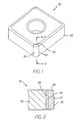
- FIGS. 1 and 2 illustrate one embodiment of the coated cutting tool generally designated as cutting tool 20.
- Cutting tool 20 has a body 22 that contains a notch or pocket 24.
- the body 22 can be made from a number of materials, but one preferred material is cobalt cemented tungsten carbide wherein the cobalt comprises about 6 weight percent of the cemented tungsten carbide and the tungsten carbide comprises about 94 weight percent of the cemented tungsten carbide.
- the notch 24 is located at one corner of the body 22, but it should be appreciated that the notch could be at opposite corners or at all four corners of the body 22.
- a polycrystalline cubic boron nitride (PcBN) blank 25 is brazed to the body 22 within the notch 24.
- the PcBN blank 25 comprises a carbide support 26 on which there is a layer of polycrystalline cubic boron nitride 27.
- the typical PcBN insert is a mixture of cubic boron nitride and another material such as, for example, titanium carbide, or some other suitable binder material.
- a braze joint 28 is at the juncture between the body 22 and the PcBN blank 25. Specific braze alloys will be described hereinafter.
- the preferred braze alloy for this application is a high temperature braze alloy in which the liquidus temperature (i.e., the lowest temperature at which the alloy is completely liquid) is at least about 900 degrees Centigrade, and even more preferably, the liquidus temperature is at least about 1000 degrees Centigrade. Braze alloys such as those listed in Table 1 are useful high temperature braze alloys.
- the cutting tool has a coating 30 applied thereto.
- the coating is also shown as a single layer. It is typical, however, that the coating may comprise more than one layer as will become apparent from the specific coating schemes described hereinafter.
- Cutting tool 40 is one example of a threading tool.
- Cutting tool 40 includes a body 42 that contains a pocket 44 and an aperture 45.
- the body 42 may be made from a number of materials including cobalt cemented tungsten carbide.
- a polycrystalline cubic boron nitride blank 46 is brazed within the pocket 44.
- the PcBN blank 46 comprises a PcBN layer 48 and a cobalt cemented tungsten carbide support 50.
- the PcBN layer 48 is affixed to the support 50.
- the PcBN blank 46 has a rake surface 52 and flank surfaces 54 wherein the rake surface 52 and the flank surfaces 54 intersect to form a cutting edge 56.
- the composition of the PcBN layer may vary depending upon the specific application.
- One specific composition for the PcBN layer is KD050 wherein KD050 has a composition that comprises about 50 volume percent cubic boron nitride and about 50 volume percent titanium carbide.
- the support 50 may also comprise any one of a variety of compositions depending upon the application.
- the PcBN blank 46 has a multi-layer coating applied thereto.
- the coating comprises six layers, and the coating scheme is applied in the following steps beginning with preparation of the substrate surface first and applying the coating layer to the substrate surface: (1) etching the substrate surface with titanium tetrachloride and aluminum chloride gases; (2) applying via CVD a coating of titanium nitride (coating layer 56) at a temperature of about 900 degrees Centigrade to a thickness that ranges between about 0.5 micrometers and about 3 micrometers with a preferred thickness that equals about 1 micrometers; (3) applying via CVD a coating of titanium carbonitride (coating layer 58) at a temperature of about 880 degrees Centigrade to a thickness that ranges between about 1 micrometers and about 10 micrometers with a preferred thickness that equals about 3 micrometers; (4) applying via CVD a coating of titanium carbonitride (coating layer 60) at a temperature of about 1000 degrees Centigrade to a thickness that ranges between
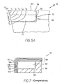
- FIGS. 5 and 6 there is shown the arrangement of a PcBN blank 70 brazed into the pocket 72 of a body 74 for a threading tool generally designated as 76.
- the PcBN blank 70 comprises a layer of PcBN 78 and a cobalt cemented tungsten carbide support 80.
- the PcBN blank 70 has a rake surface 84 and a flank surface 86.
- the rake surface 84 and the flank surface 86 intersect to form a cutting edge 88.
- the coating is removed from FIGS. 5 and 6 .
- a way to optimize the ability of the braze joint to withstand the temperatures that exist at the braze joint during a cutting operation is to locate the braze joint an optimum distance away from the point of contact between the PcBN blank (i.e., the cutting edge) and the workpiece material.
- the dimensions of the PcBN blank determine the distance between the point of contact and the braze joint.
- the selection of these dimensions is based on balancing the cost of increasing the size of the layer of PcBN or increasing the size of the support (or a combination of increasing the size of the layer of PcBN and the size of the support) against the extent of thermal protection for the braze joint due to the distance between the point of contact and the braze joint.
- the size (and hence the cost) of the PcBN piece is balanced against the extent of thermal protection of the braze joint due to the distance between the point of contact and the braze joint.
- FIG. 5A is a schematic view that shows thermal gradient lines T max and T 1 through T 5 for the coated cutting tool 76 as would occur during a material removal operation.
- the maximum temperature is (T max ) is at the point of contact between the cutting edge of the PcBN blank 70 and the workpiece material.
- the temperature gradient lines T 1 , T 2 , T 3 , T 4 , and T 5 represent five different temperatures at various distances away from the point of contact. As one can appreciate, the temperature decreases as one moves farther away from the point of contact.
- the temperature gradient has the following relationship: T 1 >T 2 >T 3 >T 4 >T 5 .
- the braze joint 82 comprises the joint between the PcBN blank 70 and the pocket 72 contained in the cutting tool body 74 wherein the braze joint 82 has two principal portions. One portion is between the PcBN blank and the seating (or horizontal in FIG. 5A ) surface of the pocket and the other portion is between the PcBN blank and the backing (or vertical on FIG. 5A ) surface. These temperature gradient lines show that the braze joint 82 is exposed to the higher temperatures at a location near the point of contact and that the temperature decreases as one moves farther away from the point of contact. By selecting certain dimensions of the PcBN blank that impact upon the location of the braze joint relative to the cutting edge, one can select the temperature that exists at the braze joint or at least provide some degree of thermal protection for the braze joint.
- the thickness of the support is typically increased since it is the least expensive component of these two components of the superhard blank.
- the extent to which the thickness of the support is increased depends upon the cutting temperatures and the properties (e.g., the liquidus temperature and the shear strength) of the particular braze alloy.
- the thickness of the support should be sufficient so that the temperature that exists at the braze joint, which in FIG. 5A would be about T 5 , would be less than the liquidus temperature of the braze alloy and so that the braze alloy would possess sufficient shear strength so as to maintain the integrity of the braze joint so as to thereby retain the PcBN blank to the cutting tool body against the cutting forces that would be exerted on the PcBN blank.
- the length "a" of the PcBN blank 70 is 0.190 inches (4.82 millimeters); the thickness “d” of the PcBN layer 78 is 0.030 inches (0.76 millimeters); the thickness "c” of the support 80 is 0.160 inches (4.1millimeters); and the overall thickness "b" of the PcBN blank 70 is 0.190 inches (4.83 millimeters).
- the leg length of the PcBN blank is dimension "e", and it equals about 0.220 inches (5.59 millimeters).
- FIG. 7 there is shown a cross-sectional view of a comparative coated cutting tool generally designated as 90 wherein the cutting tool 90 has a PcBN blank 92 brazed into the pocket 94 of the tool body 96.
- the PcBN blank 92 is comprised entirely of polycrystalline cubic boron nitride.
- PcBN blank 92 that is comprised entirely of polycrystalline cubic boron nitride is a PcBN material sold under the designation AMBORITE (Grade AMB 90) by Element Six wherein the AMBORITE (Grade AMB 90) PcBN material comprises about 90 volume percent cubic boron nitride and about 10 volume percent comprising the sum of aluminum nitride, titanium diboride and silicon carbide.
- a coating scheme for the AMBORTTE (Grade AMB 90) PcBN material comprises: a chemical vapor deposition coating scheme applied at a temperature between about 970 degrees Centigrade and about 1000 degrees Centigrade having an initial layer of alumina, then a layer of titanium carbonitride, followed by a layer of titanium oxycarbonitride, followed by a layer of titanium aluminum oxycarbonitride, followed by a thick layer of alumina, then a layer of titanium nitride, then a layer of titanium carbonitride, and a final layer of titanium nitride.
- the thickness of the thick alumina layer was between about 5 and about 6 micrometers.
- the thickness of the layers beneath the thicker alumina layer was about 3 micrometers, and the thickness of the layers on top of the thicker alumina layer was about 2.5 micrometers.
- the coating scheme is applied in the following steps: (1) etching the substrate surface with titanium tetrachloride and aluminum chloride gases; (2) applying via CVD a coating of aluminum oxide (coating layer 100) at a temperature of about 1000 degrees Centigrade to a thickness that ranges between about 0.5 micrometers and about 10 micrometers with a preferred thickness that equals about 1micrometer, (3) applying via CVD a coating of titanium nitride (coating layer 102) at a temperature of about 1000 degrees Centigrade to a thickness that ranges between about 0.5 micrometers and about 6 micrometers with a preferred thickness that equals about 1 micrometers; (4) applying via CVD a coating of titanium carbonitride (coating layer 104) at a temperature of about 990 degrees Centigrade to a thickness that ranges between about 0.5 micrometers and about 8 micrometers with a preferred thickness that equals about 2 micrometers; (5)
- FIG. 8 shows a coated cutting tool generally designated as 116.
- Cutting tool 116 has a superhard blank 118.
- Cutting tool 116 is a grooving tool that is designated as a TOP NOTCH® tool.
- FIG. 9 shows a coated cutting tool generally designated as 120.
- Cutting tool 120 has a superhard blank 122.
- Cutting tool 120 is a threading tool that is designated as a TOP NOTCH® tool.
- Table 1 Examples of Useful Braze Alloys Braze Alloy Composition (weight percent) Liquidus (Degrees Centigrade) Solidus (Degrees Centigrade) Melting Point (Degrees Centigrade) Shear Strength (pounds) Gold-Copper 50% Au 50% Cu 969 954 954 13,752 Gold-Copper-Nickel 35% Au 62% Cu 3% Ni 1028 973 973 12,844 Gold-Copper 37.5% Au 62.5% Cu 1015 940 940 13,023 Bau-4 Gold-Nickel 82% Au 18% Ni 948 948 948 21,686 Bau-6 Gold-Nickel-Palladium 70% Au 22% Ni 8% Pd 1045 1006 1006 26,670 Silver-Palladium 95% Ag 5% Pd 995 970 970 Not Measured In the Table 1 above, the shear strength is
- Table 2 provides information that is necessary to fully understand the coating schemes that are set forth below in Tables 3 through 7.
- Tables 3 through 7 contain examples of coating schemes that are applicable to the polycrystalline cubic boron nitride cutting tools of the invention.
- the cutting tools used the KD050 composition of polycrystalline cubic boron nitride.
- KD050 composition comprised about 50 volume percent cubic boron nitride and about 50 volume percent titanium carbide.
- Tables 3 through 7 each set forth the details regarding one series of the coating schemes.
- the left hand column identifies the tool number and lists the composition of the polycrystalline cubic boron nitride layer.
- the composition of the PcBN is either KD050 or KD120 as set forth above.
- the first thickness measurement represents the total thickness of the layers of from the substrate to the alumina layer.
- the second thickness measurement represents the thickness of the alumina layer.
- the third thickness measurement represents the thickness of the layers on top of the alumina layer.
- Another coating scheme comprises the following steps: (1) etching the blank surface with titanium tetrachloride and aluminum chloride gases; (2) applying via CVD a coating of titanium nitride at a temperature of about 900 degrees Centigrade to a thickness that ranges between about 0.5 micrometers and about 3.0 micrometers with a preferred thickness that equals about 1 micrometers; (3) applying via CVD a coating of titanium carbonitride at a temperature of about 880 degrees Centigrade to a thickness that ranges between about 1.5 micrometers and about 10.0 micrometers with a preferred thickness that equals about 4 micrometers; (4) applying via CVD a coating of titanium carbonitride at a temperature of about 1000 degrees Centigrade to a thickness that ranges between about 0.5 micrometers and about 5 micrometers with a preferred thickness that equals about 1 micrometers; (5) applying via CVD a bonding layer of titanium oxycarbonitride at a temperature of about 1000 degrees Centigrade to a thickness that ranges between about 0.1 micro
- Another coating scheme comprises the steps of: (1) applying by CVD (880 degrees Centigrade) a layer of titanium nitride to a thickness that ranges between about 0.5 micrometers and about 3 micrometers with a preferred thickness that equals about 1 micrometers; (2) applying by moderate temperature CVD (880 degrees Centigrade) a layer of titanium carbonitride to a thickness that ranges between about 1 micrometers and about 10 micrometers with a preferred thickness that equals about 2 micrometers; (3) applying by high temperature CVD (1000 degrees Centigrade) a layer of titanium carbonitride to a thickness that ranges between about 0.5 micrometers and about 6 micrometers with a preferred thickness that equals about 1 micrometers; (4) applying via CVD a bonding layer of titanium oxycarbonitride at a temperature of about 1000 degrees Centigrade to a thickness that ranges between about 0.1 micrometers and about 4.0 micrometers with a preferred thickness that equals about 0.3 micrometers; (5) applying via CVD a bonding layer
- Applicants further contemplate the use of a coating scheme that contains at least one layer comprising a nitride, carbide, carbonitride, oxynitride, oxycarbonitride, or oxycarbide of one or more of titanium, vanadium, chromium, zirconium, niobium, molybdenum, hafnium, tantalum, tungsten, aluminum, and silicon.
- This coating scheme includes as a possible layer a layer of titanium aluminum nitride applied by physical vapor deposition.
- the coated cutting tools that use the high temperature braze alloys especially when coupled with the coating schemes containing layers of MT-TiN/MT-TiCN/HT-TiCN/TiOCN/TiAlOCN/Al 2 O 3 and, MT-TN/MT-TiCN/HT-TiCN/TiOCN/TiAlOCN/Al 2 O 3 /HT-TiCN/HT-TiN, have shown excellent performance results. Along this line, applicants have found that the results are very good in the hard turning of hard steels such as D3 tool steel.
- the coated cutting tools that have coatings such as, for example, titanium aluminum nitride or alumina, use the design and geometry of the superhard blanks disclosed herein, regardless of the braze alloy used to braze the superhard blank to the cutting tool body, also have experienced improved performance. It appears that the design and geometry of the superhard blank have resulted in the reduction of the exposure of the braze joint to the temperatures generated at the point of contact between the cutting tool and the workpiece material.
- a constant volume threading method One specific method of threading that has provided excellent results when using these cutting tools (i.e., threading tools) is a constant volume threading method.
- the depth of the pass is constantly decreased so that the volume of material removed from the workpiece is constant for each pass.
- accumulated depth initial depth of cut (doc) • (No. pass) 1 ⁇ 2 to arrive at the depth of cut for each pass.
- the Table 8 below sets forth an example of this method showing the first four passes. Additional passes determined per the calculation are necessary to obtain an external thread depth of .0789 inches.
- the constant volume threading method can be described as a method of removing material in a threading operation from a workpiece comprising a ferrous alloy having a hardness between about 50 Rockwell C and about 65 Rockwell C using a coated cutting tool.
- the method has the following steps: providing a coated cutting tool having body containing a pocket where a superhard blank is brazed using a braze alloy into the pocket to form a braze joint wherein the braze alloy having a liquidus temperature of at least about 900 degrees Centigrade wherein the braze alloy is selected from the group comprising a nickel-gold braze alloy containing nickel and gold, a copper-gold braze alloy containing copper and gold, a gold-copper-nickel braze alloy contains gold and copper and nickel, a silver-titanium-copper braze alloy containing silver and titanium and copper, and a silver-palladium braze alloy containing silver and palladium; and engaging the workpiece with the coated cutting tool on multiple passes wherein each pass removes a volume of material
- one or more threading passes may remove either a lower volume of material than calculated per the formula or a lower volume of material than removed in the previous pass.
- such a method includes the step of engaging the workpiece with the coated cutting tool on multiple passes wherein each pass removes a volume of material substantially equal to or less than the volume of material removed from the workpiece in the previous pass.
Landscapes
- Engineering & Computer Science (AREA)
- Mechanical Engineering (AREA)
- Chemical & Material Sciences (AREA)
- Chemical Kinetics & Catalysis (AREA)
- Materials Engineering (AREA)
- Metallurgy (AREA)
- Organic Chemistry (AREA)
- Cutting Tools, Boring Holders, And Turrets (AREA)
- Knives (AREA)
- Ceramic Products (AREA)
- Polishing Bodies And Polishing Tools (AREA)
Claims (28)
- Beschichtetes Schneidwerkzeug, umfassend:einen Körper, wobei der Körper eine Tasche enthält;einen Rohling aus polykristallinem kubischem Bornitrid, wobei der Rohling unter Verwendung einer Hartlotlegierung in die Tasche gelötet ist;wobei die Hartlotlegierung eine Liquidustemperatur von mindestens etwa 900 Grad Celsius aufweist undeine Beschichtung auf das Schneidwerkzeug aufgebracht ist;dadurch gekennzeichnet, dass der Rohling aus polykristallinem kubischem Bornitrid weiterhin eine Stütze enthält, auf der die Schicht aus polykristallinem kubischem Bornitrid aufgebracht ist.
- Beschichtetes Schneidwerkzeug nach Anspruch 1, wobei die Beschichtung durch physikalische Gasphasenabscheidung aufgebracht wird.
- Beschichtetes Schneidwerkzeug nach Anspruch 1, wobei die Beschichtung durch eine Kombination aus physikalischer Gasphasenabscheidung und chemischer Gasphasenabscheidung aufgebracht wird.
- Beschichtetes Schneidwerkzeug nach Anspruch 1, wobei die Beschichtung durch chemische Gasphasenabscheidung aufgebracht wird.
- Beschichtetes Schneidwerkzeug nach einem der vorhergehenden Ansprüche, wobei die Hartlotlegierung Gold und Kupfer umfasst und das Gold in einer Menge im Bereich zwischen etwa 30 Gewichtsprozent und etwa 60 Gewichtsprozent vorliegt und das Kupfer in einer Menge im Bereich zwischen etwa 40 Gewichtsprozent und etwa 70 Gewichtsprozent vorliegt.
- Beschichtetes Schneidwerkzeug nach Anspruch 5, wobei die Hartlotlegierung weiterhin Nickel enthält und das Nickel in einer Menge zwischen etwa 2 Gewichtsprozent und etwa 7 Gewichtsprozent vorliegt.
- Beschichtetes Schneidwerkzeug nach Anspruch 5 oder 6, wobei die Hartlotlegierung zwischen etwa 35 Gewichtsprozent und etwa 40 Gewichtsprozent Gold, zwischen etwa 60 Gewichtsprozent und etwa 65 Gewichtsprozent Kupfer und zwischen etwa 1 Gewichtsprozent und etwa 5 Gewichtsprozent Nickel umfasst.
- Beschichtetes Schneidwerkzeug nach einem der Ansprüche 5 bis 7, wobei die Hartlotlegierung zwischen etwa 30 Gewichtsprozent und etwa 40 Gewichtsprozent Gold und zwischen etwa 60 Gewichtsprozent und etwa 70 Gewichtsprozent Kupfer umfasst.
- Beschichtetes Schneidwerkzeug nach Anspruch 5, wobei die Hartlotlegierung etwa 50 Gewichtsprozent Gold und etwa 50 Gewichtsprozent Kupfer umfasst.
- Beschichtetes Schneidwerkzeug nach Anspruch 5, wobei die Hartlotlegierung etwa 37,5 Gewichtsprozent Gold und etwa 62,5 Gewichtsprozent Kupfer umfasst.
- Beschichtetes Schneidwerkzeug nach einem der Ansprüche 1 bis 4, wobei die Hartlotlegierung Gold und Nickel umfasst und das Gold in einer Menge im Bereich zwischen etwa 65 Gewichtsprozent und etwa 90 Gewichtsprozent vorliegt und das Nickel in einer Menge im Bereich zwischen etwa 15 Gewichtsprozent und etwa 25 Gewichtsprozent vorliegt.
- Beschichtetes Schneidwerkzeug nach Anspruch 11, wobei die Hartlotlegierung weiterhin Palladium enthält und das Palladium in einer Menge zwischen etwa 5 Gewichtsprozent und etwa 15 Gewichtsprozent vorliegt.
- Beschichtetes Schneidwerkzeug nach Anspruch 11 oder 12, wobei die Hartlotlegierung zwischen etwa 65 Gewichtsprozent und etwa 75 Gewichtsprozent Gold, zwischen etwa 20 Gewichtsprozent und etwa 25 Gewichtsprozent Nickel und zwischen etwa 5 Gewichtsprozent und etwa 10 Gewichtsprozent Palladium umfasst.
- Beschichtetes Schneidwerkzeug nach Anspruch 13, wobei das Hartlot etwa 70 Gewichtsprozent Gold, etwa 22 Gewichtsprozent Nickel und etwa 8 Gewichtsprozent Palladium umfasst.
- Beschichtetes Schneidwerkzeug nach Anspruch 11, wobei die Hartlotlegierung zwischen etwa 80 Gewichtsprozent und etwa 85 Gewichtsprozent Gold und zwischen etwa 15 Gewichtsprozent und etwa 20 Gewichtsprozent Nickel umfasst.
- Beschichtetes Schneidwerkzeug nach einem der Ansprüche 1 bis 4, wobei die Hartlotlegierung zwischen etwa 90 Gewichtsprozent und etwa 98 Gewichtsprozent Silber und zwischen etwa 2 Gewichtsprozent und etwa 10 Gewichtsprozent Palladium umfasst.
- Beschichtetes Schneidwerkzeug nach Anspruch 16, wobei die Hartlotlegierung zwischen etwa 93 Gewichtsprozent und etwa 97 Gewichtsprozent Silber und zwischen etwa 3 Gewichtsprozent und etwa 7 Gewichtsprozent Palladium umfasst.
- Beschichtetes Schneidwerkzeug nach einem der vorhergehenden Ansprüche, wobei die Liquidustemperatur der Hartlotlegierung mindestens etwa 940 Grad Celsius beträgt.
- Beschichtetes Schneidwerkzeug nach einem der vorhergehenden Ansprüche, wobei die Liquidustemperatur der Hartlotlegierung mindestens etwa 1000 Grad Celsius beträgt.
- Beschichtetes Schneidwerkzeug nach einem der vorhergehenden Ansprüche, wobei die Beschichtung mindestens eine durch chemische Gasphasenabscheidung bei einer unter der Liquidustemperatur der Hartlotlegierung liegenden Temperatur aufgebrachte Schicht aus Aluminiumoxid enthält.
- Beschichtetes Schneidwerkzeug nach Anspruch 20, wobei das Beschichtungsverfahren weiterhin eine durch chemische Gasphasenabscheidung bei einer unter der Liquidustemperatur der Hartlotlegierung liegenden Temperatur aufgebrachte Schicht aus Titanoxycarbonitrid enthält.
- Beschichtetes Schneidwerkzeug nach Anspruch 20 oder 21, wobei das Beschichtungsverfahren weiterhin eine durch chemische Gasphasenabscheidung bei einer unter der Liquidustemperatur der Hartlotlegierung liegenden Temperatur aufgebrachte Schicht aus Titanaluminiumoxycarbonitrid enthält.
- Beschichtetes Schneidwerkzeug nach einem der Ansprüche 20 bis 22, wobei das Beschichtungsverfahren weiterhin mindestens eine durch chemische Gasphasenabscheidung bei einer unter der Liquidustemperatur der Hartlotlegierung liegenden Temperatur aufgebrachte Schicht aus Titancarbonitrid enthält.
- Beschichtetes Schneidwerkzeug nach einem der Ansprüche 20 bis 23, wobei das Beschichtungsverfahren weiterhin mindestens eine durch chemische Gasphasenabscheidung bei einer unter der Liquidustemperatur der Hartlotlegierung liegenden Temperatur aufgebrachte Schicht aus Titannitrid enthält.
- Beschichtetes Schneidwerkzeug nach einem der vorhergehenden Ansprüche, wobei die Beschichtung mindestens eine durch physikalische Gasphasenabscheidung aufgebrachte Schicht aus Titanaluminiumnitrid enthält.
- Beschichtetes Schneidwerkzeug nach einem der vorhergehenden Ansprüche, wobei der Rohling aus polykristallinem kubischem Bornitrid eine Schicht aus polykristallinem kubischem Bornitrid umfasst, umfassend etwa 50 Volumenprozent kubisches Bornitrid und etwa 50 Volumenprozent Titancarbid.
- Beschichtetes Schneidwerkzeug nach einem der Ansprüche 1 bis 25, wobei der Rohling aus polykristallinem kubischem Bornitrid etwa 90 Volumenprozent kubisches Bornitrid und etwa 10 Volumenprozent Aluminiumnitrid und Titandiborid und Siliziumcarbid umfasst.
- Beschichtetes Schneidwerkzeug nach einem der vorhergehenden Ansprüche, wobei die Beschichtung mindestens eine Schicht enthält, die ein Nitrid, Carbid, Carbonitrid, Oxynitrid, Oxycarbonitrid oder Oxycarbid von einem oder mehreren von Titan, Vanadium, Chrom, Zirkonium, Niob, Molybdän, Hafnium, Tantal, Wolfram, Aluminium und Silizium umfasst.
Priority Applications (1)
| Application Number | Priority Date | Filing Date | Title |
|---|---|---|---|
| PL04754560T PL1633523T3 (pl) | 2003-06-17 | 2004-06-07 | Pokrywane narzędzie skrawające z super twardą, twardo wlutowaną wkładką skrawającą |
Applications Claiming Priority (2)
| Application Number | Priority Date | Filing Date | Title |
|---|---|---|---|
| US10/463,379 US7592077B2 (en) | 2003-06-17 | 2003-06-17 | Coated cutting tool with brazed-in superhard blank |
| PCT/US2004/017989 WO2005000518A2 (en) | 2003-06-17 | 2004-06-07 | Coated cutting tool with brazed-in superhard blank |
Publications (2)
| Publication Number | Publication Date |
|---|---|
| EP1633523A2 EP1633523A2 (de) | 2006-03-15 |
| EP1633523B1 true EP1633523B1 (de) | 2010-09-15 |
Family
ID=33517091
Family Applications (1)
| Application Number | Title | Priority Date | Filing Date |
|---|---|---|---|
| EP04754560A Revoked EP1633523B1 (de) | 2003-06-17 | 2004-06-07 | Beschichtetes schneidwerkzeug mit einem eingelöteten superhartrohling |
Country Status (8)
| Country | Link |
|---|---|
| US (2) | US7592077B2 (de) |
| EP (1) | EP1633523B1 (de) |
| JP (1) | JP2006528076A (de) |
| CN (1) | CN1805821A (de) |
| AT (1) | ATE481206T1 (de) |
| DE (1) | DE602004029163D1 (de) |
| PL (1) | PL1633523T3 (de) |
| WO (1) | WO2005000518A2 (de) |
Families Citing this family (58)
| Publication number | Priority date | Publication date | Assignee | Title |
|---|---|---|---|---|
| US7429152B2 (en) | 2003-06-17 | 2008-09-30 | Kennametal Inc. | Uncoated cutting tool using brazed-in superhard blank |
| TWI247994B (en) * | 2004-05-28 | 2006-01-21 | Asustek Comp Inc | Main-board and control method thereof |
| DE102004063816B3 (de) * | 2004-12-30 | 2006-05-18 | Walter Ag | Al2O3-Multilagenplatte |
| US8109349B2 (en) | 2006-10-26 | 2012-02-07 | Schlumberger Technology Corporation | Thick pointed superhard material |
| US7328832B2 (en) | 2005-09-28 | 2008-02-12 | General Electric Company | Gold/nickel/copper brazing alloys for brazing WC-Co to titanium alloys |
| US7434720B2 (en) * | 2005-10-13 | 2008-10-14 | General Electric Company | Gold/nickel/copper/titanium brazing alloys for brazing WC-Co to titanium alloys |
| US7461772B2 (en) * | 2005-10-28 | 2008-12-09 | General Electric Company | Silver/aluminum/copper/titanium/nickel brazing alloys for brazing WC-Co to titanium alloys |
| US7293688B2 (en) * | 2005-11-14 | 2007-11-13 | General Electric Company | Gold/nickel/copper/aluminum/silver brazing alloys for brazing WC-Co to titanium alloys |
| KR20080094664A (ko) * | 2005-12-12 | 2008-10-23 | 엘리먼트 씩스 (프로덕션) (피티와이) 리미티드 | Pcbn 절삭 공구 부품 |
| US8080312B2 (en) * | 2006-06-22 | 2011-12-20 | Kennametal Inc. | CVD coating scheme including alumina and/or titanium-containing materials and method of making the same |
| US7637574B2 (en) | 2006-08-11 | 2009-12-29 | Hall David R | Pick assembly |
| US8714285B2 (en) | 2006-08-11 | 2014-05-06 | Schlumberger Technology Corporation | Method for drilling with a fixed bladed bit |
| US7669674B2 (en) | 2006-08-11 | 2010-03-02 | Hall David R | Degradation assembly |
| US8622155B2 (en) | 2006-08-11 | 2014-01-07 | Schlumberger Technology Corporation | Pointed diamond working ends on a shear bit |
| US8567532B2 (en) | 2006-08-11 | 2013-10-29 | Schlumberger Technology Corporation | Cutting element attached to downhole fixed bladed bit at a positive rake angle |
| US8590644B2 (en) | 2006-08-11 | 2013-11-26 | Schlumberger Technology Corporation | Downhole drill bit |
| US8215420B2 (en) | 2006-08-11 | 2012-07-10 | Schlumberger Technology Corporation | Thermally stable pointed diamond with increased impact resistance |
| WO2008105915A2 (en) * | 2006-08-11 | 2008-09-04 | Hall David R | Thick pointed superhard material |
| US9145742B2 (en) | 2006-08-11 | 2015-09-29 | Schlumberger Technology Corporation | Pointed working ends on a drill bit |
| US9051795B2 (en) | 2006-08-11 | 2015-06-09 | Schlumberger Technology Corporation | Downhole drill bit |
| US9068410B2 (en) | 2006-10-26 | 2015-06-30 | Schlumberger Technology Corporation | Dense diamond body |
| US8960337B2 (en) | 2006-10-26 | 2015-02-24 | Schlumberger Technology Corporation | High impact resistant tool with an apex width between a first and second transitions |
| US9051794B2 (en) | 2007-04-12 | 2015-06-09 | Schlumberger Technology Corporation | High impact shearing element |
| AT505759B1 (de) * | 2007-11-22 | 2009-04-15 | Boehlerit Gmbh & Co Kg | Rotierend eingesetztes schneidwerkzeug zum bearbeiten von holz |
| US8540037B2 (en) | 2008-04-30 | 2013-09-24 | Schlumberger Technology Corporation | Layered polycrystalline diamond |
| US8061457B2 (en) * | 2009-02-17 | 2011-11-22 | Schlumberger Technology Corporation | Chamfered pointed enhanced diamond insert |
| US8701799B2 (en) | 2009-04-29 | 2014-04-22 | Schlumberger Technology Corporation | Drill bit cutter pocket restitution |
| JP4647016B2 (ja) * | 2009-05-27 | 2011-03-09 | 独立行政法人産業技術総合研究所 | 接合体 |
| SE533883C2 (sv) * | 2009-06-01 | 2011-02-22 | Seco Tools Ab | Nanolaminerat belagt skärverktyg |
| KR101104493B1 (ko) | 2009-06-17 | 2012-01-12 | 한국야금 주식회사 | 절삭공구 또는 내마모성 공구용 표면 피복 박막 |
| JP5447845B2 (ja) * | 2010-03-26 | 2014-03-19 | 三菱マテリアル株式会社 | 表面被覆切削工具 |
| CN103228393B (zh) * | 2010-11-26 | 2016-06-08 | 住友电气工业株式会社 | 接合体 |
| WO2012079769A1 (en) | 2010-12-17 | 2012-06-21 | Seco Tools Ab | Coated cubic boron nitride tool for machining applications |
| US8574728B2 (en) | 2011-03-15 | 2013-11-05 | Kennametal Inc. | Aluminum oxynitride coated article and method of making the same |
| CN102924086B (zh) * | 2012-11-22 | 2013-12-11 | 山东轻工业学院 | 添加六方氮化硼的硼化钛基自润滑陶瓷刀具材料的制备方法 |
| US9017809B2 (en) | 2013-01-25 | 2015-04-28 | Kennametal Inc. | Coatings for cutting tools |
| US9138864B2 (en) | 2013-01-25 | 2015-09-22 | Kennametal Inc. | Green colored refractory coatings for cutting tools |
| US9427808B2 (en) | 2013-08-30 | 2016-08-30 | Kennametal Inc. | Refractory coatings for cutting tools |
| CN104030690B (zh) * | 2014-06-09 | 2015-10-07 | 河海大学 | 一种氮化钛-二硼化钛-立方氮化硼复合材料的制备方法 |
| CN104072146B (zh) * | 2014-07-22 | 2015-10-14 | 江阴市赛英电子有限公司 | 一种复合包覆氮化硼基多元纳米复合陶瓷工模具材料及其制备方法 |
| US11358241B2 (en) * | 2015-04-23 | 2022-06-14 | Kennametal Inc. | Cutting tools having microstructured and nanostructured refractory surfaces |
| CN105541368B (zh) * | 2016-01-21 | 2018-05-08 | 哈尔滨工业大学(威海) | 一种采用AuPd钎料对Al2O3陶瓷与钛环的钎焊方法 |
| AT15546U1 (de) * | 2016-09-19 | 2017-12-15 | Ceratizit Luxembourg S À R L | Werkzeug-Schneidkörper, Werkzeug und Verfahren zu dessen Herstellung |
| EP3357615B1 (de) * | 2016-12-20 | 2023-01-18 | Sumitomo Electric Hardmetal Corp. | Schneidwerkzeug und verfahren zur herstellung davon |
| CN107570772B (zh) * | 2017-09-07 | 2020-04-28 | 株洲钻石切削刀具股份有限公司 | 一种表面具有多种不同涂层的切削刀片 |
| US10245645B1 (en) * | 2017-10-02 | 2019-04-02 | Kennametal Inc. | Tool carrier with notch, cutting insert and method for making same |
| KR102730560B1 (ko) | 2017-11-27 | 2024-11-14 | 시카 테크놀러지 아게 | 2-성분 가압식 캔 |
| CN110394830A (zh) * | 2018-04-24 | 2019-11-01 | 武汉苏泊尔炊具有限公司 | 刀具及该刀具的加工方法 |
| CN109158625A (zh) * | 2018-08-14 | 2019-01-08 | 株洲钻石切削刀具股份有限公司 | 一种后刀面具有不同涂层的切削刀片 |
| US11229957B2 (en) * | 2018-10-02 | 2022-01-25 | Jakob Lach Gmbh & Co. Kg | Method for producing a cutting tool for the machining of workpieces and cutting tool |
| CN109321798A (zh) * | 2018-10-30 | 2019-02-12 | 湖南工业大学 | 一种硬质合金刀具涂层材料及其制备方法 |
| CN111558733A (zh) * | 2020-05-07 | 2020-08-21 | 郑州立钻超硬材料制品有限公司 | 多晶立方氮化硼切削刀具 |
| GB202019612D0 (en) * | 2020-12-11 | 2021-01-27 | Element Six Uk Ltd | Friction stir welding tool assembly |
| CN113042932A (zh) * | 2021-03-23 | 2021-06-29 | 无锡日联科技股份有限公司 | 一种tu1无氧铜真空钎焊钎料及其应用 |
| CN113913729B (zh) * | 2021-10-09 | 2022-11-22 | 阳江市高功率激光应用实验室有限公司 | 一种刀刃强化方法 |
| CN114749747A (zh) * | 2022-04-12 | 2022-07-15 | 昆明凯航光电科技有限公司 | 一种蓝宝石球罩与钛合金焊接的制备方法 |
| CN114986015B (zh) * | 2022-06-07 | 2023-09-08 | 合肥工业大学智能制造技术研究院 | 用于钼合金和石墨钎焊的高温钎料及制备方法和钎焊工艺 |
| WO2024094370A1 (en) * | 2022-10-31 | 2024-05-10 | Asml Netherlands B.V. | A coated assembly with a brazed feature and a ceramic cvd coating; and processes of fabricating the same |
Family Cites Families (71)
| Publication number | Priority date | Publication date | Assignee | Title |
|---|---|---|---|---|
| US3743489A (en) | 1971-07-01 | 1973-07-03 | Gen Electric | Abrasive bodies of finely-divided cubic boron nitride crystals |
| US3745623A (en) | 1971-12-27 | 1973-07-17 | Gen Electric | Diamond tools for machining |
| IE42084B1 (en) | 1974-09-18 | 1980-06-04 | De Beers Ind Diamond | Abrasive bodies |
| US4186628A (en) | 1976-11-30 | 1980-02-05 | General Electric Company | Rotary drill bit and method for making same |
| US4319707A (en) | 1978-01-10 | 1982-03-16 | General Electric Company | Brazing apparatus to manufacture composite compact components |
| US4225322A (en) | 1978-01-10 | 1980-09-30 | General Electric Company | Composite compact components fabricated with high temperature brazing filler metal and method for making same |
| US4536442A (en) | 1979-08-23 | 1985-08-20 | General Electric Company | Process for making diamond and cubic boron nitride compacts |
| JPS5659598A (en) | 1979-10-23 | 1981-05-23 | Nippon Kogaku Kk <Nikon> | Spectacle frame |
| DE3365680D1 (en) * | 1982-09-16 | 1986-10-02 | De Beers Ind Diamond | Abrasive bodies comprising boron nitride |
| SU1144800A1 (ru) | 1982-09-27 | 1985-03-15 | Предприятие П/Я Р-6930 | Сверло |
| US4527998A (en) | 1984-06-25 | 1985-07-09 | General Electric Company | Brazed composite compact implements |
| US4650776A (en) | 1984-10-30 | 1987-03-17 | Smith International, Inc. | Cubic boron nitride compact and method of making |
| US4647546A (en) | 1984-10-30 | 1987-03-03 | Megadiamond Industries, Inc. | Polycrystalline cubic boron nitride compact |
| US4772294A (en) | 1985-07-05 | 1988-09-20 | The General Electric Company | Brazed composite compact implements |
| CA1313762C (en) | 1985-11-19 | 1993-02-23 | Sumitomo Electric Industries, Ltd. | Hard sintered compact for a tool |
| US5255475A (en) | 1985-12-13 | 1993-10-26 | Oerlikon Geartec Ag | Tool for grinding the teeth of bevel gears having longitudinally curved teeth |
| US4714385A (en) | 1986-02-27 | 1987-12-22 | General Electric Company | Polycrystalline diamond and CBN cutting tools |
| US4702649A (en) | 1986-02-27 | 1987-10-27 | General Electric Company | Polycrystalline diamond and CBN cutting tools |
| MX161668A (es) | 1986-03-13 | 1990-12-07 | Detroit Tool Ind | Mejoras en aparato para perforacion de piezas con fresas roscadas |
| DE3751672T2 (de) | 1986-10-06 | 1996-05-30 | De Beers Ind Diamond | Schneidelement |
| IE63857B1 (en) | 1987-07-14 | 1995-06-14 | De Beers Ind Diamond | Method of brazing |
| DE3868451D1 (de) | 1987-07-29 | 1992-03-26 | Sumitomo Electric Industries | Verfahren zur verbindung eines sinterkoerpers aus kubischem bornitrid. |
| US4931363A (en) | 1988-02-22 | 1990-06-05 | General Electric Company | Brazed thermally-stable polycrystalline diamond compact workpieces |
| US4850523A (en) | 1988-02-22 | 1989-07-25 | General Electric Company | Bonding of thermally stable abrasive compacts to carbide supports |
| US5100269A (en) | 1988-08-12 | 1992-03-31 | Kennametal Inc. | Cutting insert and clamping arrangement therefor |
| US4944772A (en) | 1988-11-30 | 1990-07-31 | General Electric Company | Fabrication of supported polycrystalline abrasive compacts |
| US4936717A (en) | 1988-12-19 | 1990-06-26 | Gte Valenite Corporation | Adjustable narrow width slotting cutter |
| US4954139A (en) | 1989-03-31 | 1990-09-04 | The General Electric Company | Method for producing polycrystalline compact tool blanks with flat carbide support/diamond or CBN interfaces |
| JPH0349834A (ja) | 1989-07-14 | 1991-03-04 | Sumitomo Electric Ind Ltd | 金を接合材とする工具及びその製造方法 |
| US4985050A (en) | 1989-08-15 | 1991-01-15 | General Electric Company | Supported thermally stable cubic boron nitride tool blanks and method for making the same |
| US5049164A (en) | 1990-01-05 | 1991-09-17 | Norton Company | Multilayer coated abrasive element for bonding to a backing |
| US5036645A (en) * | 1990-02-05 | 1991-08-06 | Oscar Mayer Foods Corporation | Method of making a recloseable package |
| US5038645A (en) | 1990-06-18 | 1991-08-13 | General Electric Company | Wear resistant cutting tools and shaping method |
| JPH0467202A (ja) * | 1990-07-07 | 1992-03-03 | Toshiba Heating Appliances Co | 状態記憶装置 |
| US5273557A (en) * | 1990-09-04 | 1993-12-28 | General Electric Company | Twist drills having thermally stable diamond or CBN compacts tips |
| GB9022191D0 (en) | 1990-10-12 | 1990-11-28 | Suisse Electronique Microtech | Cubic boron nitride(cbn)abrasive tool |
| DE4126851A1 (de) | 1991-08-14 | 1993-02-18 | Krupp Widia Gmbh | Werkzeug mit verschleissfester schneide aus kubischem bornitrid oder polykristallinem kubischem bornitrid, verfahren zu dessen herstellung sowie dessen verwendung |
| US5366522A (en) * | 1991-11-07 | 1994-11-22 | Sumitomo Electric Industries, Ltd. | Polycrystalline diamond cutting tool and method of manufacturing the same |
| JPH05140769A (ja) | 1991-11-15 | 1993-06-08 | Sumitomo Electric Ind Ltd | 多結晶ダイヤモンド工具素材及びその工具母材への接合方法 |
| GB2272703B (en) | 1992-11-20 | 1996-11-06 | Suisse Electronique Microtech | Abrasive tool having film-covered CBN grits bonded by brazing to a substrate |
| US5985228A (en) | 1992-12-22 | 1999-11-16 | General Electric Company | Method for controlling the particle size distribution in the production of multicrystalline cubic boron nitride |
| US5379854A (en) | 1993-08-17 | 1995-01-10 | Dennis Tool Company | Cutting element for drill bits |
| JPH0760547A (ja) | 1993-08-24 | 1995-03-07 | Asahi Daiyamondo Kogyo Kk | ネジ切り用加工工具及びその製造方法 |
| JPH07266106A (ja) | 1994-03-24 | 1995-10-17 | Ngk Spark Plug Co Ltd | スローアウェイチップ |
| US5512235A (en) | 1994-05-06 | 1996-04-30 | General Electric Company | Supported polycrystalline compacts having improved physical properties and method for making same |
| CA2155164C (en) | 1994-08-01 | 2001-07-10 | Satoru Kukino | Super hard composite material for tools |
| JPH08225376A (ja) | 1994-10-13 | 1996-09-03 | General Electric Co <Ge> | ろう付け可能なコバルト含有cbn成形体 |
| US5691260A (en) | 1994-12-30 | 1997-11-25 | Denki Kagaku Kogyo Kabushiki Kaisha | Cubic system boron nitride sintered body for a cutting tool |
| US5697994A (en) | 1995-05-15 | 1997-12-16 | Smith International, Inc. | PCD or PCBN cutting tools for woodworking applications |
| US5639285A (en) | 1995-05-15 | 1997-06-17 | Smith International, Inc. | Polycrystallline cubic boron nitride cutting tool |
| US5564511A (en) | 1995-05-15 | 1996-10-15 | Frushour; Robert H. | Composite polycrystalline compact with improved fracture and delamination resistance |
| US5560754A (en) | 1995-06-13 | 1996-10-01 | General Electric Company | Reduction of stresses in the polycrystalline abrasive layer of a composite compact with in situ bonded carbide/carbide support |
| US5722803A (en) | 1995-07-14 | 1998-03-03 | Kennametal Inc. | Cutting tool and method of making the cutting tool |
| US5848348A (en) | 1995-08-22 | 1998-12-08 | Dennis; Mahlon Denton | Method for fabrication and sintering composite inserts |
| US5766394A (en) | 1995-09-08 | 1998-06-16 | Smith International, Inc. | Method for forming a polycrystalline layer of ultra hard material |
| JPH09267202A (ja) | 1996-03-29 | 1997-10-14 | Ngk Spark Plug Co Ltd | スローアウェイチップ |
| US6063333A (en) | 1996-10-15 | 2000-05-16 | Penn State Research Foundation | Method and apparatus for fabrication of cobalt alloy composite inserts |
| US6041875A (en) | 1996-12-06 | 2000-03-28 | Smith International, Inc. | Non-planar interfaces for cutting elements |
| SE511211C2 (sv) | 1996-12-20 | 1999-08-23 | Sandvik Ab | Ett multiskiktbelagt skärverktyg av polykristallin kubisk bornitrid |
| EP0852167A1 (de) | 1997-01-07 | 1998-07-08 | General Electric Company | Polykristalline hochabrasive Werkzeuge aus beschichtetem kubischen Bornitrid |
| JPH10193206A (ja) | 1997-01-09 | 1998-07-28 | Mitsubishi Materials Corp | 切刃片がすぐれたろう付け接合強度を有する切削工具 |
| US6224473B1 (en) * | 1997-08-07 | 2001-05-01 | Norton Company | Abrasive inserts for grinding bimetallic components |
| US6068913A (en) | 1997-09-18 | 2000-05-30 | Sid Co., Ltd. | Supported PCD/PCBN tool with arched intermediate layer |
| US5887580A (en) | 1998-03-25 | 1999-03-30 | Smith International, Inc. | Cutting element with interlocking feature |
| JPH11320215A (ja) | 1998-05-19 | 1999-11-24 | Mitsubishi Materials Corp | 切刃片がすぐれたろう付け接合強度を有する切削工具 |
| US6214247B1 (en) | 1998-06-10 | 2001-04-10 | Tdy Industries, Inc. | Substrate treatment method |
| AU6169299A (en) | 1998-10-02 | 2000-04-26 | Sandvik Ab | Pcbn tips and coatings for use in cutting and machining hard materials |
| AU1456100A (en) | 1998-12-08 | 2000-06-26 | Robert Paul Radtke | Microwave brazing process and brazing composition for tsp diamond |
| US6358438B1 (en) * | 1999-07-30 | 2002-03-19 | Tyco Electronics Corporation | Electrically conductive polymer composition |
| CA2327092C (en) * | 1999-12-03 | 2004-04-20 | Sumitomo Electric Industries, Ltd. | Coated pcbn cutting tools |
| GB0022448D0 (en) | 2000-09-13 | 2000-11-01 | De Beers Ind Diamond | Method of making a tool insert |
-
2003
- 2003-06-17 US US10/463,379 patent/US7592077B2/en not_active Expired - Lifetime
-
2004
- 2004-06-07 JP JP2006517192A patent/JP2006528076A/ja active Pending
- 2004-06-07 EP EP04754560A patent/EP1633523B1/de not_active Revoked
- 2004-06-07 PL PL04754560T patent/PL1633523T3/pl unknown
- 2004-06-07 CN CNA2004800168435A patent/CN1805821A/zh active Pending
- 2004-06-07 DE DE602004029163T patent/DE602004029163D1/de not_active Expired - Lifetime
- 2004-06-07 AT AT04754560T patent/ATE481206T1/de not_active IP Right Cessation
- 2004-06-07 WO PCT/US2004/017989 patent/WO2005000518A2/en not_active Ceased
-
2005
- 2005-09-23 US US11/233,852 patent/US20060019118A1/en not_active Abandoned
Also Published As
| Publication number | Publication date |
|---|---|
| US20040256442A1 (en) | 2004-12-23 |
| EP1633523A2 (de) | 2006-03-15 |
| JP2006528076A (ja) | 2006-12-14 |
| ATE481206T1 (de) | 2010-10-15 |
| PL1633523T3 (pl) | 2011-02-28 |
| US20060019118A1 (en) | 2006-01-26 |
| US7592077B2 (en) | 2009-09-22 |
| CN1805821A (zh) | 2006-07-19 |
| DE602004029163D1 (de) | 2010-10-28 |
| WO2005000518A2 (en) | 2005-01-06 |
| WO2005000518A3 (en) | 2005-05-06 |
Similar Documents
| Publication | Publication Date | Title |
|---|---|---|
| EP1633523B1 (de) | Beschichtetes schneidwerkzeug mit einem eingelöteten superhartrohling | |
| EP2309355B1 (de) | Unbeschichtetes Schneidwerkzeug mit einem eingelöteten superharten Rohling | |
| EP0549585B1 (de) | Mit einer mit bindemittel angereicherter cvd- und pvd-schicht bedecktes schneidwerkzeug | |
| US6090476A (en) | Cubic boron nitride cutting tool | |
| EP0127416B1 (de) | Schneidwerkzeug und seine Herstellung und Anwendung | |
| EP1455003B1 (de) | Beschichteter Einsatz aus zementiertem Karbid | |
| JP3237060B2 (ja) | Cvd及びpvdによりコーティングされた切削工具 | |
| EP1616976B1 (de) | Beschichteter Schneideinsatz | |
| EP0074759A2 (de) | Gesinterte Hartmetallkörper mit einem mehrlagigen verschleissfesten Überzug | |
| EP0591122B1 (de) | Kugelstirnfräser | |
| US5325747A (en) | Method of machining using coated cutting tools | |
| US6575671B1 (en) | Chromium-containing cemented tungsten carbide body | |
| US6612787B1 (en) | Chromium-containing cemented tungsten carbide coated cutting insert | |
| EP0236961A1 (de) | Oberflächenbeschichteter Schneidteil | |
| WO2000052225A1 (en) | A tool having a multilayer coating comprising multiple mtcvd layers | |
| EP1614773A2 (de) | Einsatz für ein metallisches Schneidwerkzeug | |
| JPS5943246B2 (ja) | 表面被覆超硬合金製ミニチユアドリル | |
| JPH0230406A (ja) | 表面被覆炭化タングステン基超硬合金製切削工具 | |
| JPS5943248B2 (ja) | 表面被覆超硬合金製ミニチユアドリル | |
| JPH01146606A (ja) | ドリル | |
| JPS6360283A (ja) | 耐欠損性のすぐれた切削工具用表面被覆硬質合金 |
Legal Events
| Date | Code | Title | Description |
|---|---|---|---|
| PUAI | Public reference made under article 153(3) epc to a published international application that has entered the european phase |
Free format text: ORIGINAL CODE: 0009012 |
|
| 17P | Request for examination filed |
Effective date: 20051209 |
|
| AK | Designated contracting states |
Kind code of ref document: A2 Designated state(s): AT BE BG CH CY CZ DE DK EE ES FI FR GB GR HU IE IT LI LU MC NL PL PT RO SE SI SK TR |
|
| DAX | Request for extension of the european patent (deleted) | ||
| 17Q | First examination report despatched |
Effective date: 20070831 |
|
| GRAP | Despatch of communication of intention to grant a patent |
Free format text: ORIGINAL CODE: EPIDOSNIGR1 |
|
| GRAS | Grant fee paid |
Free format text: ORIGINAL CODE: EPIDOSNIGR3 |
|
| GRAA | (expected) grant |
Free format text: ORIGINAL CODE: 0009210 |
|
| AK | Designated contracting states |
Kind code of ref document: B1 Designated state(s): AT BE BG CH CY CZ DE DK EE ES FI FR GB GR HU IE IT LI LU MC NL PL PT RO SE SI SK TR |
|
| REG | Reference to a national code |
Ref country code: CH Ref legal event code: EP Ref country code: GB Ref legal event code: FG4D |
|
| REG | Reference to a national code |
Ref country code: IE Ref legal event code: FG4D |
|
| REF | Corresponds to: |
Ref document number: 602004029163 Country of ref document: DE Date of ref document: 20101028 Kind code of ref document: P |
|
| REG | Reference to a national code |
Ref country code: SE Ref legal event code: TRGR |
|
| REG | Reference to a national code |
Ref country code: NL Ref legal event code: VDEP Effective date: 20100915 |
|
| PG25 | Lapsed in a contracting state [announced via postgrant information from national office to epo] |
Ref country code: AT Free format text: LAPSE BECAUSE OF FAILURE TO SUBMIT A TRANSLATION OF THE DESCRIPTION OR TO PAY THE FEE WITHIN THE PRESCRIBED TIME-LIMIT Effective date: 20100915 Ref country code: FI Free format text: LAPSE BECAUSE OF FAILURE TO SUBMIT A TRANSLATION OF THE DESCRIPTION OR TO PAY THE FEE WITHIN THE PRESCRIBED TIME-LIMIT Effective date: 20100915 |
|
| REG | Reference to a national code |
Ref country code: ES Ref legal event code: FG2A Effective date: 20110209 |
|
| PG25 | Lapsed in a contracting state [announced via postgrant information from national office to epo] |
Ref country code: CY Free format text: LAPSE BECAUSE OF FAILURE TO SUBMIT A TRANSLATION OF THE DESCRIPTION OR TO PAY THE FEE WITHIN THE PRESCRIBED TIME-LIMIT Effective date: 20100915 Ref country code: SI Free format text: LAPSE BECAUSE OF FAILURE TO SUBMIT A TRANSLATION OF THE DESCRIPTION OR TO PAY THE FEE WITHIN THE PRESCRIBED TIME-LIMIT Effective date: 20100915 |
|
| REG | Reference to a national code |
Ref country code: PL Ref legal event code: T3 |
|
| PG25 | Lapsed in a contracting state [announced via postgrant information from national office to epo] |
Ref country code: GR Free format text: LAPSE BECAUSE OF FAILURE TO SUBMIT A TRANSLATION OF THE DESCRIPTION OR TO PAY THE FEE WITHIN THE PRESCRIBED TIME-LIMIT Effective date: 20101216 |
|
| PG25 | Lapsed in a contracting state [announced via postgrant information from national office to epo] |
Ref country code: PT Free format text: LAPSE BECAUSE OF FAILURE TO SUBMIT A TRANSLATION OF THE DESCRIPTION OR TO PAY THE FEE WITHIN THE PRESCRIBED TIME-LIMIT Effective date: 20110117 Ref country code: CZ Free format text: LAPSE BECAUSE OF FAILURE TO SUBMIT A TRANSLATION OF THE DESCRIPTION OR TO PAY THE FEE WITHIN THE PRESCRIBED TIME-LIMIT Effective date: 20100915 Ref country code: NL Free format text: LAPSE BECAUSE OF FAILURE TO SUBMIT A TRANSLATION OF THE DESCRIPTION OR TO PAY THE FEE WITHIN THE PRESCRIBED TIME-LIMIT Effective date: 20100915 Ref country code: SK Free format text: LAPSE BECAUSE OF FAILURE TO SUBMIT A TRANSLATION OF THE DESCRIPTION OR TO PAY THE FEE WITHIN THE PRESCRIBED TIME-LIMIT Effective date: 20100915 Ref country code: RO Free format text: LAPSE BECAUSE OF FAILURE TO SUBMIT A TRANSLATION OF THE DESCRIPTION OR TO PAY THE FEE WITHIN THE PRESCRIBED TIME-LIMIT Effective date: 20100915 Ref country code: EE Free format text: LAPSE BECAUSE OF FAILURE TO SUBMIT A TRANSLATION OF THE DESCRIPTION OR TO PAY THE FEE WITHIN THE PRESCRIBED TIME-LIMIT Effective date: 20100915 |
|
| PLBI | Opposition filed |
Free format text: ORIGINAL CODE: 0009260 |
|
| PG25 | Lapsed in a contracting state [announced via postgrant information from national office to epo] |
Ref country code: BE Free format text: LAPSE BECAUSE OF FAILURE TO SUBMIT A TRANSLATION OF THE DESCRIPTION OR TO PAY THE FEE WITHIN THE PRESCRIBED TIME-LIMIT Effective date: 20100915 |
|
| PLAX | Notice of opposition and request to file observation + time limit sent |
Free format text: ORIGINAL CODE: EPIDOSNOBS2 |
|
| 26 | Opposition filed |
Opponent name: SANDVIK INTELLECTUAL PROPERTY AB Effective date: 20110613 Opponent name: ISCAR LTD Effective date: 20110615 |
|
| PLAN | Information deleted related to communication of a notice of opposition and request to file observations + time limit |
Free format text: ORIGINAL CODE: EPIDOSDOBS2 |
|
| PLAX | Notice of opposition and request to file observation + time limit sent |
Free format text: ORIGINAL CODE: EPIDOSNOBS2 |
|
| PLAF | Information modified related to communication of a notice of opposition and request to file observations + time limit |
Free format text: ORIGINAL CODE: EPIDOSCOBS2 |
|
| PLAN | Information deleted related to communication of a notice of opposition and request to file observations + time limit |
Free format text: ORIGINAL CODE: EPIDOSDOBS2 |
|
| PLAX | Notice of opposition and request to file observation + time limit sent |
Free format text: ORIGINAL CODE: EPIDOSNOBS2 |
|
| PG25 | Lapsed in a contracting state [announced via postgrant information from national office to epo] |
Ref country code: DK Free format text: LAPSE BECAUSE OF FAILURE TO SUBMIT A TRANSLATION OF THE DESCRIPTION OR TO PAY THE FEE WITHIN THE PRESCRIBED TIME-LIMIT Effective date: 20100915 |
|
| REG | Reference to a national code |
Ref country code: DE Ref legal event code: R026 Ref document number: 602004029163 Country of ref document: DE Effective date: 20110613 |
|
| PLAF | Information modified related to communication of a notice of opposition and request to file observations + time limit |
Free format text: ORIGINAL CODE: EPIDOSCOBS2 |
|
| REG | Reference to a national code |
Ref country code: CH Ref legal event code: PL |
|
| PLAF | Information modified related to communication of a notice of opposition and request to file observations + time limit |
Free format text: ORIGINAL CODE: EPIDOSCOBS2 |
|
| REG | Reference to a national code |
Ref country code: IE Ref legal event code: MM4A |
|
| PLBB | Reply of patent proprietor to notice(s) of opposition received |
Free format text: ORIGINAL CODE: EPIDOSNOBS3 |
|
| PG25 | Lapsed in a contracting state [announced via postgrant information from national office to epo] |
Ref country code: LI Free format text: LAPSE BECAUSE OF NON-PAYMENT OF DUE FEES Effective date: 20110630 Ref country code: CH Free format text: LAPSE BECAUSE OF NON-PAYMENT OF DUE FEES Effective date: 20110630 Ref country code: IE Free format text: LAPSE BECAUSE OF NON-PAYMENT OF DUE FEES Effective date: 20110607 |
|
| PGFP | Annual fee paid to national office [announced via postgrant information from national office to epo] |
Ref country code: TR Payment date: 20120503 Year of fee payment: 9 |
|
| PGFP | Annual fee paid to national office [announced via postgrant information from national office to epo] |
Ref country code: PL Payment date: 20120416 Year of fee payment: 9 Ref country code: SE Payment date: 20120612 Year of fee payment: 9 Ref country code: GB Payment date: 20120606 Year of fee payment: 9 Ref country code: FR Payment date: 20120619 Year of fee payment: 9 |
|
| PGFP | Annual fee paid to national office [announced via postgrant information from national office to epo] |
Ref country code: IT Payment date: 20120616 Year of fee payment: 9 |
|
| PGFP | Annual fee paid to national office [announced via postgrant information from national office to epo] |
Ref country code: ES Payment date: 20120726 Year of fee payment: 9 |
|
| PG25 | Lapsed in a contracting state [announced via postgrant information from national office to epo] |
Ref country code: MC Free format text: LAPSE BECAUSE OF NON-PAYMENT OF DUE FEES Effective date: 20110630 |
|
| PG25 | Lapsed in a contracting state [announced via postgrant information from national office to epo] |
Ref country code: LU Free format text: LAPSE BECAUSE OF NON-PAYMENT OF DUE FEES Effective date: 20110607 |
|
| PG25 | Lapsed in a contracting state [announced via postgrant information from national office to epo] |
Ref country code: BG Free format text: LAPSE BECAUSE OF FAILURE TO SUBMIT A TRANSLATION OF THE DESCRIPTION OR TO PAY THE FEE WITHIN THE PRESCRIBED TIME-LIMIT Effective date: 20101215 |
|
| PG25 | Lapsed in a contracting state [announced via postgrant information from national office to epo] |
Ref country code: HU Free format text: LAPSE BECAUSE OF FAILURE TO SUBMIT A TRANSLATION OF THE DESCRIPTION OR TO PAY THE FEE WITHIN THE PRESCRIBED TIME-LIMIT Effective date: 20100915 |
|
| PLAB | Opposition data, opponent's data or that of the opponent's representative modified |
Free format text: ORIGINAL CODE: 0009299OPPO |
|
| R26 | Opposition filed (corrected) |
Opponent name: ISCAR LTD Effective date: 20110615 |
|
| PG25 | Lapsed in a contracting state [announced via postgrant information from national office to epo] |
Ref country code: SE Free format text: LAPSE BECAUSE OF NON-PAYMENT OF DUE FEES Effective date: 20130608 |
|
| REG | Reference to a national code |
Ref country code: SE Ref legal event code: EUG |
|
| PLAB | Opposition data, opponent's data or that of the opponent's representative modified |
Free format text: ORIGINAL CODE: 0009299OPPO |
|
| GBPC | Gb: european patent ceased through non-payment of renewal fee |
Effective date: 20130607 |
|
| R26 | Opposition filed (corrected) |
Opponent name: SANDVIK INTELLECTUAL PROPERTY AB Effective date: 20110613 |
|
| REG | Reference to a national code |
Ref country code: FR Ref legal event code: ST Effective date: 20140228 |
|
| PG25 | Lapsed in a contracting state [announced via postgrant information from national office to epo] |
Ref country code: GB Free format text: LAPSE BECAUSE OF NON-PAYMENT OF DUE FEES Effective date: 20130607 |
|
| PG25 | Lapsed in a contracting state [announced via postgrant information from national office to epo] |
Ref country code: IT Free format text: LAPSE BECAUSE OF NON-PAYMENT OF DUE FEES Effective date: 20130607 Ref country code: FR Free format text: LAPSE BECAUSE OF NON-PAYMENT OF DUE FEES Effective date: 20130701 |
|
| REG | Reference to a national code |
Ref country code: ES Ref legal event code: FD2A Effective date: 20140707 |
|
| PGFP | Annual fee paid to national office [announced via postgrant information from national office to epo] |
Ref country code: DE Payment date: 20140603 Year of fee payment: 11 |
|
| RDAF | Communication despatched that patent is revoked |
Free format text: ORIGINAL CODE: EPIDOSNREV1 |
|
| REG | Reference to a national code |
Ref country code: PL Ref legal event code: LAPE |
|
| REG | Reference to a national code |
Ref country code: DE Ref legal event code: R103 Ref document number: 602004029163 Country of ref document: DE Ref country code: DE Ref legal event code: R064 Ref document number: 602004029163 Country of ref document: DE |
|
| PG25 | Lapsed in a contracting state [announced via postgrant information from national office to epo] |
Ref country code: PL Free format text: LAPSE BECAUSE OF NON-PAYMENT OF DUE FEES Effective date: 20130607 Ref country code: ES Free format text: LAPSE BECAUSE OF NON-PAYMENT OF DUE FEES Effective date: 20130608 |
|
| RDAG | Patent revoked |
Free format text: ORIGINAL CODE: 0009271 |
|
| STAA | Information on the status of an ep patent application or granted ep patent |
Free format text: STATUS: PATENT REVOKED |
|
| 27W | Patent revoked |
Effective date: 20141006 |
|
| REG | Reference to a national code |
Ref country code: DE Ref legal event code: R107 Ref document number: 602004029163 Country of ref document: DE Effective date: 20150319 |
|
| REG | Reference to a national code |
Ref country code: SE Ref legal event code: ECNC |
|
| PG25 | Lapsed in a contracting state [announced via postgrant information from national office to epo] |
Ref country code: TR Free format text: LAPSE BECAUSE OF NON-PAYMENT OF DUE FEES Effective date: 20130607 |