EP1634738A2 - Bedieneinheit für eine Fahrzeugkomponente - Google Patents
Bedieneinheit für eine Fahrzeugkomponente Download PDFInfo
- Publication number
- EP1634738A2 EP1634738A2 EP05019483A EP05019483A EP1634738A2 EP 1634738 A2 EP1634738 A2 EP 1634738A2 EP 05019483 A EP05019483 A EP 05019483A EP 05019483 A EP05019483 A EP 05019483A EP 1634738 A2 EP1634738 A2 EP 1634738A2
- Authority
- EP
- European Patent Office
- Prior art keywords
- loading bridge
- semi
- trailer according
- bridge part
- loading
- Prior art date
- Legal status (The legal status is an assumption and is not a legal conclusion. Google has not performed a legal analysis and makes no representation as to the accuracy of the status listed.)
- Granted
Links
Images



Classifications
-
- B—PERFORMING OPERATIONS; TRANSPORTING
- B62—LAND VEHICLES FOR TRAVELLING OTHERWISE THAN ON RAILS
- B62D—MOTOR VEHICLES; TRAILERS
- B62D53/00—Tractor-trailer combinations; Road trains
- B62D53/04—Tractor-trailer combinations; Road trains comprising a vehicle carrying an essential part of the other vehicle's load by having supporting means for the front or rear part of the other vehicle
- B62D53/06—Semi-trailers
- B62D53/061—Semi-trailers of flat bed or low loader type or fitted with swan necks
- B62D53/062—Semi-trailers of flat bed or low loader type or fitted with swan necks having inclinable, lowerable platforms; Lift bed trailers; Straddle trailers
Definitions
- the present invention relates to a semi-trailer with a viewed in the direction of travel, divided into a front part and a rear part loading bridge.
- semi-trailers with one, viewed in the direction of travel, straight or continuous loading bridge.
- Such vehicles are particularly suitable, for example, for the easy loading of goods packed on pallets, since the pallets can be transported obstacle-free over the entire length of the loading bridge with a forklift or hand pallet truck.
- the invention has for its object to provide a suitable for use in various fields of application semitrailer.
- the semi-trailer according to the invention has a loading bridge, which is divided in the longitudinal direction in a front part and a rear part.
- the rear loading bridge part is according to the invention height adjustable connected to the front loading bridge part. Due to the height-adjustable connection, the rear loading bridge part can be lowered relative to the front loading bridge part, i. the semi-trailer from a straight, continuous loading bridge position are converted into a loading platform with cranked loading bridge. In this way, the loading bridge of the semi-trailer can be adapted to the respective needs.
- the height adjustability can be realized, for example, in that the rear loading bridge part in the manner of a carriage, i. straight or with a degree of freedom, slidably connected to the front loading bridge part and can be moved in parallel in this way.
- the height adjustment can also be realized in that the rear Lademaschinenteils is articulated on the front Lademaschinenteil, that is connected via a hinge connection with the front Lademaschinenteil.
- this linkage may look like this in that the rear loading bridge part can be displaced curvilinearly or with two degrees of freedom from a higher position into a lower position and vice versa by means of a rotary push joint with a joint axis provided on the one loading bridge part, which is displaceable along a cam disk provided on the other loading bridge part.
- the articulation can also be done via a parallelogram with two equal long, superimposed arms, which are articulated at the front and at the rear Lademaschinenteil each about a transverse to the longitudinal direction of the loading bridge pivot axis.
- the articulation of the rear Lademaschinenteils on the front Lade Portugalnteil is reduced to a handlebar pivotally about a transverse to the longitudinal direction of the loading bridge first pivot axis pivotally connected to the rear end of the front Lademaschinenteils and about a transverse to the longitudinal direction of the loading bridge second pivot axis connected to the front end of the rear loading bridge part.
- This type of articulation which can be carried out particularly easily considering the required strength and rigidity in design terms, thus allowing movement of the rear loading bridge part with two degrees of freedom. Two degrees of freedom make it possible to respond more flexibly to possible manufacturing accuracies compared to just one degree of freedom.
- the linkage can be realized with the aid of a link construction designed such that the first pivot axis is laterally in a first loading bridge position in which the front loading bridge part and the rear loading bridge part are at the same height and provide a straight, continuous loading area Viewing below the second pivot axis and in a second loading bridge position, in which the rear loading bridge part is lowered relative to the front cargo bed part and a cranked loading surface is provided, is located above the second pivot axis.
- a mechanically, hydraulically or pneumatically actuated height adjustment device for height adjustment is provided in a preferred embodiment.
- the height adjustment device in addition to a semitrailer already present in a support device over which the semi-trailer can be supported in a state uncoupled from a towing vehicle, height adjustable on the ground, another, in the longitudinal direction of the loading bridge of the the aforementioned support device arranged height-adjustable support device comprises.
- the adjustment of the rear Lade Hampshires with respect to the front Lade Portugalnteil can then be carried out with the aid of the two support devices.
- the rear dock leveler can be supported and adjusted in height independently of the front support device with the aid of the two support devices.
- the height adjustment of the rear Lademaschinenteils relative to the front Lademaschinenteil can be done mechanically, hydraulically or pneumatically. Further, the height adjustment can be made stepless or stepped or limited to the fact that the rear loading bridge part can assume exactly two relative positions relative to the front loading bridge part.
- the rear dock leveler is relative to the front dock leveler portion between a first one Loading bridge position, in which the front and the rear Lademaschinenteil lie at the same height, and a second loading bridge position in which the rear Lademaschinenteil is lowered relative to the front Lademaschinenteil, height adjustable. Due to the restriction to two altitudes of the rear Lademaschinenteils relative to the front Lademaschinenteil the structure of the dock leveler and thus of the semi-trailer simplified.
- the possible end and intermediate positions of the rear Lademaschinenteils relative to the front Lademaschinenteil can be adjusted via suitable stop surfaces on the front and rear Lademaschinenteil or on the handlebar formed from the handlebar construction and / or with the aid of a locking device, for example in the form of a pin safety. Notwithstanding the said positive locking locks but also frictionally acting detents are possible.
- the locking of the rear Lademaschinenteils takes place in a certain position relative to the front Lademaschinenteils by means of a locking device which has a displaceably mounted on the left and / or right main frame member of the one Lademaschinenteils bolt with one of the first loading hole position corresponding first receiving bore or one of the second loading bridge position corresponding second receiving bore on the left and right main frame member of the other Lademaschinenteils is engageable.
- the locking device ie the locking pin, can be arranged on the front loading bridge part as well as on the rear loading bridge part.
- the locking of the rear Lademaschinenteils relative to the front Lademaschinenteil can be made mechanically, hydraulically or pneumatically in a desired loading bridge position.
- an inventive semitrailer 1 for coupling to a (not shown) towing vehicle is shown.
- the built in frame construction dock leveler 10 of the semitrailer 1 according to the invention is in a, seen in (forward) direction of travel, front Lademaschinenteil 20 and a rear Lade Developmentnteil 40 divided at the interface S via one at the rear end of the front Lade Developmentnteils 20 and at the front end the rear cargo bed part 40 via a handlebar construction 60 are height-adjustable interconnected.
- the front loading bridge part 20 consists essentially of a frame construction 22 with a (not shown) loading platform, a coupling pin 21 for coupling the semitrailer 1 to the towing vehicle (not shown), and a front support device 28 for supporting the semitrailer 1 on the ground.
- the frame construction 22 of the front loading platform part 20 essentially consists of a left and right main frame carrier 22a or 22b, viewed in the direction of travel, which can be seen in FIG.
- Fig. 6 shows a schematic inside view of the rear end portion of the right main frame member 22b of the front loading bridge portion 20.
- a receiving bore 23b in which the axle pin 24b is received with a tight fit
- a first and a second receiving bore 26b and 27b in which, depending on whether the semi-trailer 1 in the continuous or cranked position, a transversely mounted on the rear loading bridge portion 40 locking bolt 52b of the rear loading bridge portion 40 provided locking device 50 is received in the first and second loading bridge position.
- the first and second receiving bores 26b and 27b are arranged vertically one above the other at a certain distance.
- the left main frame member 22a is constructed in mirror image to the right main frame member 22b, so that a more detailed description of the left main frame member 22a is unnecessary.
- the axle bolts 24a and 24b provided on the front docking portion 20 define a first pivot axis 28 at which the linkage structure 60 is pivotally connected to the front dock leveler portion 20.
- the front support device 28 is mounted vertically adjustable at the rear end portion of the front cargo bed portion 20 and designed for a support of the semitrailer 1 both in the empty and in the load condition.
- the support device 28 is of conventional design, so that a further description is not required.
- the adjustment of the front support device 28 may be mechanical, hydraulic or pneumatic.
- the rear dock leveler 40 resting on an axle assembly 44 consists essentially of a frame structure 42 with a loading platform (not shown), a rear support 46 for supporting the semitrailer 1 on the ground, and a locking device 50 for locking the rear deck portion 40 relative to the front dock leveler 20 in the first or second loading bridge position.
- the frame construction 42 of the rear cargo bed part 40 like the frame construction of the front cargo bed part 20, essentially consists of a left and right main frame member 42a and 42b viewed laterally, respectively, which, as seen in Fig. 5, laterally within the main frame members 22a and 22b are arranged.
- a respective axle pin 44a and 44b projecting transversely inward in the direction of travel is fixedly secured, e.g. welded or pressed.
- stops 43a and 43b are respectively provided at the predetermined location on the outside of the main frame members 42a and 42b, against which the main frame members 22a and 22b of the front loading panel portion 20 abut both in the continuous, first loading bridge position and in the cranked, second loading bridge position. as can be seen from FIGS. 3 a, 3 b, 4 a, 4 b and 5.
- Fig. 7 shows a schematic inside view of the rear end portion of the right main frame member 42b of the rear loading bridge portion 40.
- a receiving bore 43b which receives the axle bolt 44b with a tight fit
- a receiving bore 46b the transverse to the direction of travel locking pin 52b the locking device 50 for locking the front Lade Portugalnteils 20 relative to the rear Lademaschinenteils 40 in the first or second loading bridge position sliding fit receives.
- the left main frame member 42a is mirror-inverted to the right main frame member 42b, so that a detailed description of the left main frame member 42a is unnecessary.
- axle bolts 44a and 44b provided on the rear deck portion 40 define a second pivot axis 48 at which the link structure 60 is pivotally connected to the rear dock leveler portion 40.
- the rear support device 46 is height-adjustable in the region between the interface S and the axle assembly at the front end portion of the rear loading bridge portion 40 and pivotally mounted about a pivot axis 47 extending transversely to the direction of travel.
- the rear support device is designed only for supporting the semitrailer 1 in the empty state.
- the support device 46 is of conventional design, so that a further description is not required.
- the adjustment of the rear support device 46 may be mechanical, hydraulic or pneumatic.
- the locking device 50 provided on the frame construction 42 of the rear loading bridge part 40 comprises two locking bolts 52a and 52b.
- the locking bolt 52a is slidably disposed on the left main frame bracket 42a of the rear loading bridge portion 40 in the receiving bore 46a transversely of the direction of travel and can be brought by mechanical, hydraulic or pneumatic operation with the provided on the left main frame support 22b receiving bore 26a or 27a, depending on whether in the continuous, first loading bridge position or in the cranked, second loading bridge position to be locked.
- the locking pin 52b is equally slidably disposed transversely to the direction of travel on the right main frame rail 42b of the rear loading bridge portion 40 in the receiving bore 46b and may be by mechanical, hydraulic or pneumatic Operation are brought into engagement with the provided on the right main frame support 22b receiving bore 26b or 27b, depending on whether the continuous, first loading bridge position or the cranked, second loading bridge position is desired.
- the front Lademaschinenteil 20 and the rear Lademaschinenteil 40 are connected via the handlebar construction 60 height adjustable with each other.
- the handlebar construction 60 consists essentially of two transversely arranged in the direction of travel handlebars 62 and 64.
- the front in the direction of travel always front handlebar 62 is rotatably mounted on the first pivot axis formed by the axle bolts 24a and 24b.
- the handlebar tube 62 which is always located behind in the direction of travel, is rotatably mounted on the second pivot axis formed by the axle bolts 44a and 44b.
- FIG. 5 it can be seen that the front link tube 62 is longer than the rear link tube 64 due to the fact that the main frame members 22a and 22b of the front frame bridge member 20 are disposed laterally outward of the main frame members 24a and 24b, respectively.
- the front and rear handlebars 62, 64 are fixedly connected to each other by a plurality of transverse connecting webs 66 spaced apart in the longitudinal direction of the handlebars 42, 62, e.g. welded.
- the handlebar construction 60 is thus a rigid unit which is pivotally connected to the front loading bridge part 20 via the first pivot axis formed by the axle bolts 24a and 24b and pivotally connected to the rear loading bridge part 40 via the second pivot axis formed by the axle bolts 44a and 44b.
- the distance between the first and second pivot axes 28, 48 is constant. Likewise, the distance between the second pivot axis 48 and the connection axis 49 defined by the locking pins 52a, 52b constant. Furthermore, the first and second receiving holes 26b and 27b are vertically stacked.
- the rear loading bridge part 40 can therefore, with substantially constant horizontal alignment of the loading bridge 10 on a circular path with the distance between the first pivot axis 28 and the second pivot axis 48 as a radius from the continuous, first loading bridge position shown in, for example, in Fig. 1b and Fig. 2b for example, the cranked, second loading bridge position shown in Figs. 1a and 2a are adjusted about the first pivot axis 28 relative to the front loading bridge portion 20.
- the adjustment of the rear Lademaschinenteils 40 relative to the front Lademaschinenteil 20 is carried out with the aid of the two support devices 28 and 46.
- the rear loading bridge part 40 relative to the front loading bridge part 20 are easily adjusted between the first and second loading bridge position.
- the fixing of the rear loading bridge part 40 on the front loading bridge part 20 takes place in each of the two loading bridge positions in that the locking bolts 52a and 52b in the corresponding receiving holes 26a, 26b or 27a, 27b engage and secured.
- the semitrailer 1 according to the invention can therefore be used both with cranked loading bridge, ie as a so-called semi-trailer with low bed, or with straight, continuous loading bridge without cranking.
- the adjustment of the loading bridge 1 from the straight, continuous position to the bent position, as mentioned, take place mechanically, hydraulically or pneumatically via the two support devices 28, 46.
- the support devices 28, 46 may be designed so that they are spring-biased toward semi-trailer and only in the direction of the ground mechanically, hydraulically or pneumatically actuated.
- the fixation of the two loading bridge parts in the two loading bridge positions by means of the locking device 50 can be done mechanically, hydraulically or pneumatically.
- the locking device 50 can also be designed so that the locking pins 52a, 52b in the one stroke direction, for example in the stroke direction in which they are engaged in the corresponding mounting holes 26a, 26b or 27a, 27b, spring-biased and only in the other stroke direction For example, in the direction in which the lock between the front loading bridge part 20 and the rear loading bridge part 40 is released, are mechanically, hydraulically or pneumatically actuated.
- the semitrailer 1 unlike the embodiment illustrated in FIGS. 1 a, 1 b, 2 a and 2 b, can have any desired number of axes instead of the four axes shown.
- intermediate loading bridge position in addition to the loading bridge positions described above, in which the front loading bridge part 20 bears against the rear loading bridge part 40 substantially without an intermediate spacing, intermediate loading bridge position can also be realized. in that further receiving bores are provided at suitable locations between the two receiving bores 26a, 26b or 27a, 27b, into which the locking bolts 52a, 52b can engage. In the latter case, of course, the total length of the dock leveler would extend slightly.
- the invention is realized on a semi-trailer.
- the concept according to the invention of the articulation of the rear loading platform part to the front loading platform part can, however, also be transferred to a trailer in order to convert it into a kind of low loader.
- the invention is therefore not limited to a semi-trailer, although this is the presently preferred embodiment and the claims are directed to a semi-trailer, but generally applicable to vehicles such as semi-trailers and trailers. Therefore, the applicant reserves the right, at a later stage by means of a subsequent application or division, to seek protection for a vehicle which has a loading bridge longitudinally divided into a front part and a rear part, the rear loading bridge part being height-adjustable front loading bridge part is connected.
Landscapes
- Engineering & Computer Science (AREA)
- Chemical & Material Sciences (AREA)
- Combustion & Propulsion (AREA)
- Transportation (AREA)
- Mechanical Engineering (AREA)
- Vehicle Cleaning, Maintenance, Repair, Refitting, And Outriggers (AREA)
- Auxiliary Methods And Devices For Loading And Unloading (AREA)
- Axle Suspensions And Sidecars For Cycles (AREA)
- Vehicle Body Suspensions (AREA)
- Arrangement And Mounting Of Devices That Control Transmission Of Motive Force (AREA)
- Vending Machines For Individual Products (AREA)
- Sink And Installation For Waste Water (AREA)
Abstract
Description
- Die vorliegende Erfindung betrifft einen Sattelauflieger mit einer, in Fahrtrichtung betrachtet, in einen vorderen Teil und einen hinteren Teil geteilten Ladebrücke.
- Allgemein bekannt sind Sattelauflieger mit einer, in Fahrtrichtung betrachtet, geraden oder durchgängigen Ladebrücke. Derartige Fahrzeuge eignen sich im Besonderen beispielsweise für die problemlose Verladung von auf Paletten verpackten Waren, da die Paletten mit einem Gabelstapler oder Handhubwagen hindernisfrei über die gesamte Länge der Ladebrücke transportiert werden können.
- Bekannt sind weiter Sattelauflieger mit einer gestuften oder gekröpften Ladebrücke, bei der der hintere Ladebrückenteil gegenüber dem vorderen Ladebrückenteil in der Höhe abgesenkt ist. Diese Tiefbett-Bauart dient vor allem zum Transport großvolumiger Lasten, wie Fahrzeugen oder Baumaschinen.
- Die vorstehend genannten Bauarten, d.h. mit oder ohne Kröpfung, werden daher im Hinblick auf das jeweilige Anwendungsgebiet hin konzipiert. Um für Einsätze auf den verschiedenen Anwendungsgebieten gerüstet zu sein, war es daher für einen Fuhrparkbetreiber erforderlich, Fahrzeuge beider Bauarten anzuschaffen. Eine größe Zahl von Fahrzeugen im Fuhrpark bedeutet aber höhere Kosten im Zusammenhang mit der Anschaffung und Wartung des Fuhrparks.
- Der Erfindung liegt die Aufgabe zugrunde, einen für den Einsatz auf verschiedenen Anwendungsgebieten geeigneten Sattelauflieger zu schaffen.
- Diese Aufgabe wird gelöst durch einen Sattelauflieger mit den Merkmalen des Anspruchs 1. Vorteilhafte oder bevorzugte Ausführungsformen sind Gegenstand abhängiger Ansprüche.
- Der erfindungsgemäße Sattelauflieger weist eine Ladebrücke auf, die in Längsrichtung in einen vorderen Teil und einen hinteren Teil geteilt ist. Der hintere Ladebrückenteil ist erfindungsgemäß höhenverstellbar mit dem vorderen Ladebrückenteil verbunden. Durch die höhenverstellbare Verbindung kann der hintere Ladebrückenteil gegenüber dem vorderen Ladebrückenteil abgesenkt werden, d.h. der Sattelauflieger aus einer geraden, durchgängigen Ladebrückenstellung in eine Ladebrückenstellung mit gekröpfter Ladebrücke umgerüstet werden. Auf diese Weise kann die Ladebrücke des Sattelaufliegers dem jeweiligen Bedarf entsprechend angepasst werden.
- Die Höhenverstellbarkeit kann beispielsweise dadurch realisiert werden, dass der hintere Ladebrückenteil in der Art eines Schlittens, d.h. geradlinig oder mit einem Freiheitsgrad, gleitbeweglich mit dem vorderen Ladebrückenteil verbunden ist und auf diese Weise parallel verschoben werden kann.
- Die Höhenverstellung kann aber auch dadurch realisiert werden, dass der hintere Ladebrückenteils am vorderen Ladebrückenteil angelenkt ist, d.h. über eine Gelenkverbindung mit dem vorderen Ladebrückenteil verbunden ist. Diese Anlenkung kann beispielsweise so aussehen, dass der hintere Ladebrückenteil über ein Drehschubgelenk mit einer an dem einen Ladebrückenteil vorgesehenen Gelenkachsen, die entlang einer an dem anderen Ladebrückenteil vorgesehenen Kurvenscheibe verschiebbar ist, krummlinig oder mit zwei Freiheitsgraden aus einer höheren Stellung in eine tiefere Stellung und umgekehrt verschoben werden kann. Die Anlenkung kann aber auch über eine Parallelogrammführung mit zwei gleich langen, übereinander angeordneten Lenkern erfolgen, die am vorderen wie auch am hinteren Ladebrückenteil jeweils um eine quer zur Längsrichtung der Ladebrücke verlaufende Schwenkachse angelenkt sind.
- In einer bevorzugten Ausführungsform ist die Anlenkung des hinteren Ladebrückenteils am vorderen Ladebrückenteil auf einen Lenker reduziert, der um eine quer zur Längsrichtung der Ladebrücke verlaufende erste Schwenkachse schwenkbar mit dem hinteren Ende des vorderen Ladebrückenteils sowie um eine quer zur Längsrichtung der Ladebrücke verlaufende zweite Schwenkachse schwenkbar mit dem vorderen Ende des hinteren Ladebrückenteils verbunden ist. Diese Art der Anlenkung, die sich unter Beachtung der erforderlichen Festigkeit und Steifigkeit in konstruktiver Hinsicht besonders einfach ausführen lässt, gestattet damit eine Bewegung des hinteren Ladebrückenteils mit zwei Freiheitsgraden. Durch zwei Freiheitsgrade kann im Vergleich zu nur einem Freiheitsgrad flexibler auf mögliche Fertigungsgenauigkeiten reagiert werden. In diesem Fall kann die Anlenkung mit Hilfe einer Lenkerkonstruktion verwirklicht werden, die so ausgelegt ist, dass die erste Schwenkachse in einer ersten Ladebrückenstellung, in der der vordere Ladebrückenteil und der hintere Ladebrückenteil auf gleicher Höhe liegen und eine gerade, durchgängige Ladefläche bereitstellen, bei seitlicher Betrachtung unterhalb der zweiten Schwenkachse und in einer zweiten Ladebrückenstellung, in der der hintere Ladebrückenteil relativ zum vorderen Ladebrückenteil abgesenkt ist und eine gekröpfte Ladefläche bereitgestellt wird, oberhalb der zweiten Schwenkachse liegt.
- Zur Höhenverstellung des hinteren Ladebrückenteils relativ zum vorderen Ladebrückenteil ist in einer bevorzugten Ausführungsform eine mechanisch, hydraulisch oder pneumatisch betätigbare Höhenverstellvorrichtung zur Höhenverstellung vorgesehen. Als besonders einfach zu realisieren hat es sich herausgestellt, wenn die Höhenverstellvorrichtung neben einer bei einem Sattelauflieger ohnehin vorhandenen Stützvorrichtung, über die der Sattelauflieger in einem von einem Zugfahrzeug abgekuppelten Zustand, höhenverstellbar am Boden abgestützt werden kann, eine weitere, in Längsrichtung der Ladebrücke von der erstgenannten Stützvorrichtung angeordnete höhenverstellbare Stützvorrichtung umfasst. Die Verstellung des hinteren Ladebrückenteils gegenüber dem vorderen Ladebrückenteil kann dann unter Zuhilfenahme der beiden Stützvorrichtungen durchgeführt werden. Beispielsweise kann der hintere Ladebrückenteil, wenn der Sattelauflieger zum Einen auf dem Fahrgestell eines Zugfahrzeugs und zum Anderen auf einer üblicherweise vorhandenen Achsanordnung ruht, unter Zuhilfenahme der beiden Stützvorrichtung unabhängig vom vorderen Stützvorrichtung abgestützt und in der Höhe verstellt werden.
- In jedem Fall kann die Höhenverstellung des hinteren Ladebrückenteils relativ zum vorderen Ladebrückenteil mechanisch, hydraulisch oder pneumatisch erfolgen. Weiter kann die Höhenverstellung stufenlos oder gestuft erfolgen bzw. darauf beschränkt sein, dass das hintere Ladebrückenteil genau zwei Relativstellungen gegenüber dem vorderen Ladebrückenteil annehmen kann. So ist in einer bevorzugten Ausführungsform der hintere Ladebrückenteil relativ zum vorderen Ladebrückenteil zwischen einer ersten Ladebrückenstellung, in der der vordere und der hintere Ladebrückenteil auf gleicher Höhe liegen, und einer zweiten Ladebrückenstellung, in der der hintere Ladebrückenteil gegenüber dem vorderen Ladebrückenteil abgesenkt ist, höhenverstellbar. Durch die Beschränkung auf zwei Höhenlagen des hinteren Ladebrückenteils relativ zum vorderen Ladebrückenteil vereinfacht sich der Aufbau der Ladebrücke und damit des Sattelaufliegers.
- Im Sinne einer einfachen Bauweise mit der erforderlichen Festigkeit und Steifigkeit sind der vordere und hintere Ladebrückenteil jeweils in Rahmenbauweise beispielsweise mit einem Zentralrahmenträger oder, wie in der bevorzugten Ausführungsform, mit einem, in Längsrichtung der Ladebrücke betrachtet, linken und rechten Hauptrahmenträger ausgeführt, wobei die Lenkerkonstruktion quer zur Längsrichtung der Ladebrücke zwischen den Hauptrahmenträgern des vorderen und hinteren Ladebrückenteils angeordnet ist.
- Die möglichen End- und Zwischenstellungen des hinteren Ladebrückenteils relativ zum vorderen Ladebrückenteil können über geeignete Anschlagflächen am vorderen und hinteren Ladebrückenteil oder an der aus den Lenkern gebildeten Lenkerkonstruktion und/oder mit Hilfe einer Arretiervorrichtung, beispielsweise in Form einer Bolzensicherung, eingestellt werden. Abweichend zu den genannten formschlüssig wirkenden Arretierungen sind aber auch kraftschlüssig wirkende Arretierungen möglich.
- In der bevorzugten Ausführungsform erfolgt die Arretierung des hinteren Ladebrückenteils in einer bestimmten Position relativ zum vorderen Ladebrückenteils mit Hilfe einer Arretiervorrichtung, die einen am linken und/oder rechten Hauptrahmenträger des einen Ladebrückenteils verschiebbar gelagerten Bolzen aufweist, der mit einer der ersten Ladebrückenstellung entsprechenden ersten Aufnahmebohrung oder einer der zweiten Ladebrückenstellung entsprechenden zweiten Aufnahmebohrung am linken bzw. rechten Hauptrahmenträger des anderen Ladebrückenteils in Eingriff bringbar ist. Die Arretiervorrichtung, d.h. die Arretierbolzen, kann am vorderen Ladebrückenteil wie auch am hinteren Ladebrückenteil angeordnet sein.
- Ebenso wie die Höhenverstellung kann die Arretierung des hinteren Ladebrückenteils relativ zum vorderen Ladebrückenteil in einer gewünschten Ladebrückenstellung mechanisch, hydraulisch oder pneumatisch erfolgen.
-
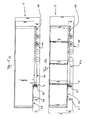
- Fig. 1a zeigt eine schematische Seitenansicht des erfindungsgemäßen Sattelaufliegers mit gekröpfter Ladebrücke;
- Fig. 1b zeigt eine schematische Seitenansicht des erfindungsgemäßen Sattelaufliegers mit durchgehender Ladebrücke;
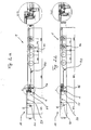
- Fig. 2a zeigt eine schematische Seitenansicht des erfindungsgemäßen Sattelaufliegers mit gekröpfter Ladebrücke ohne Abdeckung;
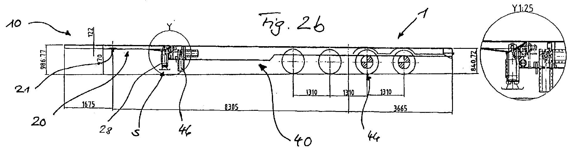
- Fig. 2b zeigt eine schematische Seitenansicht des erfindungsgemäßen Sattelaufliegers mit durchgehender Ladebrücke ohne Abdeckung;
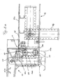
- Fig. 3a zeigt den in Fig. 2a mit "X" angegeben Bereich der Ladebrücke in vergrößertem Maßstab;
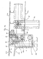
- Fig. 3b zeigt den in Fig. 2b mit "Y" angegeben Bereich der Ladebrücke in vergrößertem Maßstab;
- Fig. 4a zeigt den in Fig. 2a mit "X" angegeben Bereich der Ladebrücke in vergrößertem Maßstab ohne Fußstützen;
- Fig. 4b zeigt den in Fig. 2b mit "Y" angegeben Bereich der Ladebrücke in vergrößertem Maßstab ohne Fußstützen;
- Fig. 5 zeigt eine schematische Draufsicht auf die Rahmenkonstruktion der Ladebrücke des erfindungsgemäßen Sattelaufliegers im Bereich der Schnittstelle zwischen dem vorderen und hinteren Ladebrückenteil;
- Fig. 6 zeigt eine schematische Innenseitenansicht des hinteren Endabschnitts eines Hauptrahmenträgers der Rahmenkonstruktion des vorderen Ladebrückenteils; und
- Fig. 7 zeigt eine schematische Innenseitenansicht des vorderen Endabschnitts eines Hauptrahmenträgers der Rahmenkonstruktion des hinteren Ladebrückenteils.
- Ausführliche Beschreibung einer bevorzugten Ausführungsform
- In den Figuren ist ein erfindungsgemäßer Sattelauflieger 1 zur Ankopplung an ein (nicht gezeigtes) Zugfahrzeug gezeigt.
- Die in Rahmenbauweise gebaute Ladebrücke 10 des erfindungsgemäßen Sattelaufliegers 1 ist in einen, in (Vorwärts-)Fahrtrichtung betrachtet, vorderen Ladebrückenteil 20 und einen hinteren Ladebrückenteil 40 geteilt, die an der Schnittstelle S über eine am hinteren Ende des vorderen Ladebrückenteils 20 und am vorderen Ende des hinteren Ladebrückenteils 40 über eine Lenkerkonstruktion 60 höhenverstellbar miteinander verbunden sind. In einer ersten Ladebrückenstellung, die in den Figuren 1b und 2b veranschaulicht ist, liegen der vordere Ladebrückenteil 20 und der hintere Ladebrückenteil 40 auf gleicher Höhe, so dass die Ladebrücke 10 gerade oder durchgängig ist, während in einer zweiten Ladebrückenstellung, die in den Figuren 1a und 2a veranschaulicht ist, der hintere Ladebrückenteil 40 gegenüber dem vorderen Ladebrückenteil 20 abgesenkt ist, so dass die Ladebrücke 10 im Bereich der Schnittstelle S eine Kröpfung aufweist.
- Der vordere Ladebrückenteil 20 besteht im Wesentlichen aus einer Rahmenkonstruktion 22 mit einer (nicht gezeigten) Ladeplattform, einem Kupplungszapfen 21 zur Ankopplung des Sattelaufliegers 1 an das (nicht gezeigte) Zugfahrzeug, sowie einer vorderen Stützvorrichtung 28 zur Abstützung des Sattelaufliegers 1 auf dem Boden.
- Die Rahmenkonstruktion 22 des vorderen Ladebrückenteils 20 besteht im Wesentlichen aus einem, in Fahrtrichtung betrachtet, linken und rechten Hauptrahmenträger 22a bzw. 22b, die in Fig. 5 zu sehen sind. An dem dem hinteren Ladebrückenteil 40 zugewandten Endabschnitt der Hauptrahmenträger 22a und 22b des vorderen Ladebrückenteils 20 ist jeweils ein in Fahrtrichtung quer nach innen ragenden Achsbolzen 24a bzw. 24b fest angebracht, z.B. verschweißt oder eingepresst.
- Fig. 6 zeigt eine schematische Innenseitenansicht des hinteren Endabschnitts des rechten Hauptrahmenträgers 22b des vorderen Ladebrückenteils 20. Zu erkennen sind im Besonderen eine Aufnahmebohrung 23b, in der der Achsbolzen 24b mit einem Festsitz aufgenommen wird, sowie eine erste und eine zweite Aufnahmebohrung 26b bzw. 27b, in denen abhängig davon, ob sich der Sattelauflieger 1 in der durchgehenden oder gekröpften Stellung befindet, ein am hinteren Ladebrückenteil 40 quer zur Fahrtrichtung verschiebbar gelagerter Arretierbolzen 52b einer am hinteren Ladebrückenteil 40 vorgesehenen Arretiervorrichtung 50 in der ersten bzw. zweiten Ladebrückenstellung aufgenommen wird. Die erste und zweite Aufnahmebohrung 26b und 27b sind vertikal übereinander in einem bestimmten Abstand angeordnet.
- Der linke Hauptrahmenträger 22a ist spiegelbildlich zum rechten Hauptrahmenträger 22b aufgebaut, so dass sich eine ausführlichere Beschreibung des linken Hauptrahmenträgers 22a erübrigt.
- Die am vorderen Ladebrückenteil 20 vorgesehenen Achsbolzen 24a und 24b definieren eine erste Schwenkachse 28, an der die Lenkerkonstruktion 60 schwenkbeweglich mit dem vorderen Ladebrückenteil 20 verbunden ist.
- Die vordere Stützvorrichtung 28 ist am hinteren Endabschnitt des vorderen Ladebrückenteils 20 höhenverstellbar montiert und für eine Abstützung des Sattelaufliegers 1 sowohl im Leer- als auch im Lastzustand ausgelegt. Die Stützvorrichtung 28 ist von üblicher Bauart, so dass eine weitere Beschreibung nicht erforderlich ist. Die Verstellung der vorderen Stützvorrichtung 28 kann mechanisch, hydraulisch oder pneumatisch erfolgen.
- Der auf einer Achsanordnung 44 ruhende hintere Ladebrückenteil 40 besteht im Wesentlichen aus einer Rahmenkonstruktion 42 mit einer (nicht gezeigten) Ladeplattform, einer hinteren Stützvorrichtung 46 zur Abstützung des Sattelaufliegers 1 auf dem Boden sowie einer Arretiervorrichtung 50 zur Arretierung des hinteren Ladebrückenteils 40 relativ zum vorderen Ladebrückenteil 20 in der ersten oder zweiten Ladebrückenstellung.
- Die Rahmenkonstruktion 42 des hinteren Ladebrückenteils 40 besteht ebenso wie die Rahmenkonstruktion des vorderen Ladebrückenteils 20 im Wesentlichen aus einem, in Fahrtrichtung betrachtet, linken und rechten Hauptrahmenträger 42a bzw. 42b, die, wie es in Fig. 5 zu sehen ist, seitlich innerhalb der Hauptrahmenträger 22a und 22b angeordnet sind. An den dem vorderen Ladebrückenteil 20 zugewandten vorderen Endabschnitten der Hauptrahmenträger 42a und 42b des hinteren Ladebrückenteils 40 ist jeweils ein in Fahrtrichtung quer nach innen ragender Achsbolzen 44a bzw. 44b fest angebracht, z.B. verschweißt oder eingepresst. Des Weiteren sind an der Außenseite der Hauptrahmenträger 42a und 42b jeweils an vorgegebener Stelle Anschläge 43a und 43b vorgesehen, an der die Hauptrahmenträger 22a bzw. 22b des vorderen Ladebrückenteils 20 sowohl in der durchgängigen, ersten Ladebrückenstellung als auch in der gekröpften, zweiten Ladebrückenstellung anliegen, wie es aus den Fig. 3a, 3b, 4a, 4b und 5 zu erkennen ist.
- Fig. 7 zeigt eine schematische Innenseitenansicht des hinteren Endabschnitts des rechten Hauptrahmenträgers 42b des hinteren Ladebrückenteils 40. Zu erkennen sind im Besonderen eine Aufnahmebohrung 43b, die den Achsbolzen 44b mit einem Festsitz aufnimmt, sowie eine Aufnahmebohrung 46b, die den quer zur Fahrtrichtung verschiebbaren Arretierbolzen 52b der Arretiervorrichtung 50 zur Arretierung des vorderen Ladebrückenteils 20 relativ zum hinteren Ladebrückenteils 40 in der ersten oder zweiten Ladebrückenstellung Gleitsitz aufnimmt.
- Der linke Hauptrahmenträger 42a ist spiegelbildlich zum rechten Hauptrahmenträger 42b aufgebaut, so dass sich eine ausführliche Beschreibung des linken Hauptrahmenträgers 42a erübrigt.
- Die an dem hinteren Ladebrückenteil 40 vorgesehenen Achsbolzen 44a und 44b definieren eine zweite Schwenkachse 48, an der die Lenkerkonstruktion 60 schwenkbar mit dem hinteren Ladebrückenteil 40 verbunden ist.
- Die hintere Stützvorrichtung 46 ist im Bereich zwischen der Schnittstelle S und der Achsanordnung am vorderen Endabschnitt des hinteren Ladebrückenteils 40 höhenverstellbar sowie um eine quer zur Fahrtrichtung verlaufende Schwenkachse 47 schwenkbar montiert. Im Gegensatz zur vorderen Stützvorrichtung 28 ist die hintere Stützvorrichtung nur zur Abstützung des Sattelaufliegers 1 im Leerzustand ausgelegt. Die Stützvorrichtung 46 ist von üblicher Bauart, so dass eine weitere Beschreibung nicht erforderlich ist. Die Verstellung der hinteren Stützvorrichtung 46 kann mechanisch, hydraulisch oder pneumatisch erfolgen.
- Wie es in Fig. 5 zu sehen ist, umfasst die an der Rahmenkonstruktion 42 des hinteren Ladebrückenteils 40 vorgesehene, im Übrigen nicht näher veranschaulichte Arretiervorrichtung 50 zwei Arretierbolzen 52a und 52b. Der Arretierbolzen 52a ist am linken Hauptrahmenträger 42a des hinteren Ladebrückenteils 40 in der Aufnahmebohrung 46a quer zur Fahrtrichtung verschiebbar angeordnet und kann durch mechanische, hydraulische oder pneumatische Betätigung in Eingriff mit der am linken Hauptrahmenträger 22b vorgesehenen Aufnahmebohrung 26a oder 27a gebracht werden, je nachdem ob in der durchgängigen, ersten Ladebrückenstellung oder in der gekröpften, zweiten Ladebrückenstellung arretiert werden soll. Der Arretierbolzen 52b ist gleichermaßen am rechten Hauptrahmenträger 42b des hinteren Ladebrückenteils 40 in der Aufnahmebohrung 46b quer zur Fahrtrichtung verschiebbar angeordnet und kann durch mechanische, hydraulische oder pneumatische Betätigung in Eingriff mit der am rechten Hauptrahmenträger 22b vorgesehenen Aufnahmebohrung 26b oder 27b gebracht werden, je nachdem ob die durchgängige, erste Ladebrückenstellung oder die gekröpfte, zweite Ladebrückenstellung gewünscht ist.
- Der vordere Ladebrückenteil 20 und der hintere Ladebrückenteil 40 sind über die Lenkerkonstruktion 60 höhenverstellbar miteinander verbunden. Die Lenkerkonstruktion 60 besteht im Wesentlichen aus zwei in Fahrtrichtung quer angeordneten Lenkerrohren 62 und 64. Das in Fahrtrichtung stets vorne liegende Lenkerrohr 62 ist drehbeweglich auf der durch die Achsbolzen 24a und 24b gebildeten ersten Schwenkachse gelagert. Ähnlich dazu ist das in Fahrtrichtung stets hinten liegende Lenkerrohr 62 drehbeweglich auf der durch die Achsbolzen 44a und 44b gebildeten zweiten Schwenkachse gelagert. In Fig. 5 ist zu sehen, dass das vordere Lenkerrohr 62 aufgrund der Tatsache, dass die Hauptrahmenträger 22a und 22b des vorderen Rahmenbrückenteils 20 seitlich außerhalb der Hauptrahmenträger 24a bzw. 24b des hinteren Rahmenbrückenteils 40 angeordnet sind, länger ist als das hintere Lenkerrohr 64.
- Das vordere und hintere Lenkerrohr 62, 64 sind durch eine Vielzahl von in Längsrichtung der Lenkerrohre 42, 62 beabstandet angeordnete Querverbindungsstege 66 fest miteinander verbunden, z.B. verschweißt. Die Lenkerkonstruktion 60 ist damit eine starre Einheit, die über die durch die Achsbolzen 24a und 24b gebildete erste Schwenkachse schwenkbar mit dem vorderen Ladebrückenteil 20 und über die durch die Achsbolzen 44a und 44b gebildete zweite Schwenkachse schwenkbar mit dem hinteren Ladebrückenteil 40 verbunden ist.
- Der Abstand zwischen der ersten und zweiten Schwenkachse 28, 48 ist konstant. Ebenso ist der Abstand zwischen der zweiten Schwenkachse 48 und der durch die Arretierbolzen 52a, 52b definierten Verbindungsachse 49 konstant. Des Weiteren liegen die erste und zweite Aufnahmebohrung 26b und 27b vertikal übereinander. Das hintere Ladebrückenteil 40 kann daher bei im Wesentlichen gleichbleibender horizontaler Ausrichtung der Ladebrücke 10 auf einer Kreisbahn mit dem Abstand zwischen der ersten Schwenkachse 28 und der zweiten Schwenkachse 48 als Radius aus der beispielsweise in Fig. 1b und Fig. 2b gezeigten durchgängigen, ersten Ladebrückenstellung in die beispielsweise in Fig. 1a und 2a gezeigte gekröpfte, zweite Ladebrückenstellung um die erste Schwenkachse 28 relativ zum vorderen Ladebrückenteil 20 verstellt werden.
- Die Verstellung des hinteren Ladebrückenteils 40 gegenüber dem vorderen Ladebrückenteil 20 erfolgt unter Zuhilfenahme der beiden Stützvorrichtungen 28 und 46. Wenn der Sattelauflieger 1 in einem an einem Zugfahrzeug angekoppelten Zustand auf der Achsanordnung 44 und der vorderen Stützvorrichtung 28 ruht, kann mit Hilfe der hinteren Stützvorrichtung 46 im Leerzustand des Sattelaufliegers 1 der hintere Ladebrückenteil 40 relativ zum vorderen Ladebrückenteil 20 problemlos zwischen der ersten und zweiten Ladebrückenstellung verstellt werden. Die Fixierung des hinteren Ladebrückenteils 40 am vorderen Ladebrückenteils 20 erfolgt in jeder der beiden Ladebrückenstellungen dadurch, dass die Arretierbolzen 52a und 52b in den entsprechenden Aufnahmebohrungen 26a, 26b oder 27a, 27b einrasten und gesichert werden.
- Der erfindungsgemäße Sattelauflieger 1 kann daher sowohl mit gekröpfter Ladebrücke, d.h. als sogenannter Semi-Sattelauflieger mit Tiefbett, oder mit gerader, durchgängiger Ladebrücke ohne Kröpfung eingesetzt werden. Die Verstellung der Ladebrücke 1 aus der geraden, durchgängigen Stellung in die gekröpfte Stellung kann, wie erwähnt, über die beiden Stützvorrichtungen 28, 46 mechanisch, hydraulisch oder pneumatisch erfolgen. Die Stützvorrichtungen 28, 46 können so ausgeführt sein, dass sie in Richtung Sattelauflieger federvorgespannt und nur in Richtung Boden mechanisch, hydraulisch oder pneumatisch betätigbar sind.
- Gleichermaßen kann die Fixierung der beiden Ladebrückenteile in den beiden Ladebrückenstellungen mit Hilfe der Arretiervorrichtung 50 mechanisch, hydraulisch oder pneumatisch erfolgen. Die Arretiervorrichtung 50 kann dabei ebenfalls so ausgeführt sein, dass die Arretierbolzen 52a, 52b in die eine Hubrichtung, beispielsweise in die Hubrichtung, in der sie in den entsprechenden Aufnahmebohrungen 26a, 26b oder 27a, 27b eingerastet sind, federvorgespannt und nur in die andere Hubrichtung, beispielsweise in die Richtung, in die Arretierung zwischen dem vorderen Ladebrückenteil 20 und dem hinteren Ladebrückenteil 40 aufgehoben wird, mechanisch, hydraulisch oder pneumatisch betätigbar sind.
- Des Weiteren kann der erfindungsgemäße Sattelauflieger 1, wie in den Figuren 1a, 1b gezeigt, mit Abdeckung oder, wie in den Figuren 2a, 2b gezeigt, ohne Abdeckung gebaut und eingesetzt werden.
- Weiter kann der erfindungsgemäße Sattelauflieger 1 abweichend von der in den Figuren 1a, 1b, 2a und 2b dargestellten Ausführungsform anstatt der gezeigten vier Achsen eine beliebige Zahl von Achsen aufweisen.
- Abweichend von der bevorzugten Ausführungsform können neben den vorstehend beschriebenen Ladebrückenstellungen, in denen der vordere Ladebrückenteil 20 im Wesentlichen ohne Zwischenabstand am hinteren Ladebrückenteil 40 anliegt, auch Zwischenladebrückenstellung realisiert werden, indem zwischen den beiden Aufnahmebohrungen 26a, 26b bzw. 27a, 27b weitere Aufnahmebohrungen an geeigneten Stellen vorgesehen werden, in die die Arretierbolzen 52a, 52b einrasten können. In letzterem Fall würde sich natürlich die Gesamtlänge der Ladebrücke geringfügig verlängern.
- In der vorstehend beschriebenen bevorzugten Ausführungsform ist die Erfindung an einem Sattelauflieger verwirklicht. Das erfindungsgemäße Konzept der Anlenkung des hinteren Ladebrückenteils an den vorderen Ladebrückenteil kann aber auch auf einen Anhänger übertragen werden, um diesen in in der Art eines Tiefladers umzurüsten. Die Erfindung ist daher nicht auf einen Sattelauflieger beschränkt, wenngleich dieser die derzeit bevorzugte Ausführungsform darstellt und die Ansprüche auf einen Sattelauflieger gerichtet sind, sondern allgemein auf Fahrzeuge, wie Sattelauflieger und Anhänger, anwendbar. Daher behält sich der Anmelder vor, zu einem späteren Zeitpunkt im Wege einer Nachanmeldung oder Teilung um Schutz für ein Fahrzeug nachzusuchen, das eine Ladebrücke aufweist, die in Längsrichtung in einen vorderen Teil und einen hinteren Teil geteilt ist, wobei der hintere Ladebrückenteil höhenverstellbar mit dem vorderen Ladebrückenteil verbunden ist.
Claims (11)
- Sattelauflieger mit einer Ladebrücke (10), die in Längsrichtung in einen vorderen Teil (20) und einen hinteren Teil (40) geteilt ist, dadurch gekennzeichnet, dass
der hintere Ladebrückenteil (40) höhenverstellbar mit dem vorderen Ladebrückenteil (20) verbunden ist. - Sattelauflieger nach Anspruch 1, dadurch gekennzeichnet, dass der hintere Ladebrückenteil (40) relativ zum vorderen Ladebrückenteil (20) zwischen einer ersten Ladebrückenstellung, in der der vordere und der hintere Ladebrückenteil auf gleicher Höhe liegen, und einer zweiten Ladebrückenstellung, in der der hintere Ladebrückenteil gegenüber dem vorderen Ladebrückenteil abgesenkt ist, höhenverstellbar ist.
- Sattelauflieger nach Anspruch 1 oder 2, dadurch gekennzeichnet, dass
der hintere Ladebrückenteil (40) höhenverstellbar am vorderen Ladebrückenteil (20) angelenkt ist. - Sattelauflieger nach Anspruch 3, gekennzeichnet durch eine Lenkerkonstruktion (60), die um eine quer zur Längsrichtung der Ladebrücke (10) verlaufende erste Schwenkachse (28) schwenkbar mit dem hinteren Ende des vorderen Ladebrückenteils (20) sowie um eine quer zur Längsrichtung der Ladebrücke (10) verlaufende zweite Schwenkachse (48) schwenkbar mit dem vorderen Ende des hinteren Ladebrückenteils (40) verbunden ist.
- Sattelauflieger nach Anspruch 4, dadurch gekennzeichnet, dass die erste Schwenkachse (28) in der ersten Ladebrückenstellung unterhalb der zweiten Schwenkachse (48) und in der zweiten Ladebrückenstellung vertikal oberhalb der zweiten Schwenkachse (48) liegt.
- Sattelauflieger nach Anspruch 4 oder 5, dadurch gekennzeichnet, dass der vordere und hintere Ladebrückenteil (20; 40) jeweils eine Rahmenkonstruktion mit einem, in Längsrichtung der Ladebrücke betrachtet, linken und rechten Hauptrahmenträger (22a, 22b; 42a, 42b) aufweisen, und die Lenkerkonstruktion (60) quer zur Längsrichtung der Ladebrücke (10) zwischen den Hauptrahmenträgern (22a, 22b; 42a, 42b) des vorderen und hinteren Ladebrückenteils (20; 40) angeordnet ist.
- Sattelauflieger nach einem der Ansprüche 1 bis 6, gekennzeichnet durch eine mechanisch, hydraulisch oder pneumatisch betätigbare Arretiervorrichtung (50) zur Arretierung des hinteren Ladebrückenteils (40) relativ zum vorderen Ladebrückenteil (20).
- Sattelauflieger nach Anspruch 6 und 7, dadurch gekennzeichnet, dass die Arretiervorrichtung einen am linken und/oder rechten Hauptrahmenträger (42a, 42b) des einen Ladebrückenteils (40) verschiebbar gelagerten Bolzen (52a, 52b) aufweist, der mit einer der ersten Ladebrückenstellung entsprechenden ersten Aufnahmebohrung (26a, 26b) oder einer der zweiten Ladebrückenstellung entsprechenden zweiten Aufnahmebohrung (27a, 27b) am linken bzw. rechten Hauptrahmenträger (22a, 22b) des anderen Ladebrückenteils (20) in Eingriff bringbar ist.
- Sattelauflieger nach einem der Ansprüche 1 bis 8, gekennzeichnet durch eine mechanisch, hydraulisch oder pneumatisch betätigbare Höhenverstellvorrichtung zur Höhenverstellung des hinteren Ladebrückenteils (40) relativ zum vorderen Ladebrückenteil (20).
- Sattelauflieger nach Anspruch 9, dadurch gekennzeichnet, dass die Höhenverstellvorrichtung zwei in Längsrichtung der Ladebrücke (10) in einem Abstand zueinander angeordnete, höhenverstellbare Stützvorrichtungen (28; 46) zur Abstützung des Sattelaufliegers am Boden umfasst.
- Sattelauflieger nach Anspruch 10, dadurch gekennzeichnet, dass die in Fahrtrichtung des Sattelaufliegers hintere Stützvorrichtung (46) um eine quer zur Längsrichtung der Ladebrücke (10) verlaufende Schwenkachse (47) schwenkbar gelagert angeordnet ist.
Applications Claiming Priority (1)
| Application Number | Priority Date | Filing Date | Title |
|---|---|---|---|
| DE202004014089U DE202004014089U1 (de) | 2004-09-10 | 2004-09-10 | Sattelauflieger |
Publications (3)
| Publication Number | Publication Date |
|---|---|
| EP1634738A2 true EP1634738A2 (de) | 2006-03-15 |
| EP1634738A3 EP1634738A3 (de) | 2006-05-31 |
| EP1634738B1 EP1634738B1 (de) | 2008-07-30 |
Family
ID=34112253
Family Applications (1)
| Application Number | Title | Priority Date | Filing Date |
|---|---|---|---|
| EP05019483A Expired - Lifetime EP1634738B1 (de) | 2004-09-10 | 2005-09-07 | Bedieneinheit für eine Fahrzeugkomponente |
Country Status (3)
| Country | Link |
|---|---|
| EP (1) | EP1634738B1 (de) |
| AT (1) | ATE402835T1 (de) |
| DE (2) | DE202004014089U1 (de) |
Family Cites Families (5)
| Publication number | Priority date | Publication date | Assignee | Title |
|---|---|---|---|---|
| US4302022A (en) * | 1979-12-31 | 1981-11-24 | Schoeffler William N | High-low trailer |
| FI900285L (fi) * | 1990-01-18 | 1991-07-19 | Valto Ilomaeki | Transportunderlag. |
| DE29615435U1 (de) * | 1996-09-05 | 1997-01-09 | Blomenröhr Fahrzeugbau GmbH, 59590 Geseke | Straßentransporter |
| US6343825B1 (en) * | 2000-07-05 | 2002-02-05 | Stuart Gee | Over the road trailer with adjustable bed configuration |
| BE1015576A3 (nl) * | 2003-06-20 | 2005-06-07 | Renders Sa | Oplegger. |
-
2004
- 2004-09-10 DE DE202004014089U patent/DE202004014089U1/de not_active Expired - Lifetime
-
2005
- 2005-09-07 EP EP05019483A patent/EP1634738B1/de not_active Expired - Lifetime
- 2005-09-07 DE DE502005004865T patent/DE502005004865D1/de not_active Expired - Lifetime
- 2005-09-07 AT AT05019483T patent/ATE402835T1/de active
Non-Patent Citations (1)
| Title |
|---|
| None |
Also Published As
| Publication number | Publication date |
|---|---|
| DE202004014089U1 (de) | 2005-01-27 |
| DE502005004865D1 (de) | 2008-09-11 |
| EP1634738A3 (de) | 2006-05-31 |
| ATE402835T1 (de) | 2008-08-15 |
| EP1634738B1 (de) | 2008-07-30 |
Similar Documents
| Publication | Publication Date | Title |
|---|---|---|
| EP0045039B1 (de) | Ladefahrzeug zur Aufnahme einer Erntebergungsvorrichtung | |
| DE69431516T2 (de) | Fahrzeug mit einem u-förmigen rahmen | |
| DE202013104703U1 (de) | Schwerlastmodulfahrzeug | |
| DE1630282A1 (de) | Wahlweise als Einzelanhaenger an eine Strassenzugmaschine oder Tandemanhaenger hinter einen identischen Anhaenger ankuppelbare Fahrgestelleinheit | |
| DE69930062T2 (de) | Vorrichtung zur Handhabung eines Behälters für ein Straßenfahrzeug | |
| DE68902688T2 (de) | Gueterzugverbundwagen. | |
| DE1921477B2 (de) | Einrichtung zum verbinden eines ladegestells mit einer sattelzugmaschine | |
| DE1630774B2 (de) | Fahrzeug zum transport insbesondere von schweren etwa der fahrzeugbreite entsprechenden lasten | |
| EP1661756B1 (de) | Autotransporter sowie Gelenkzug mit einem solchen Autotransporter | |
| EP0045398A1 (de) | Kombinierte Wechsel-Kipp-Einrichtung für Nutzfahrzeugaufbauten | |
| DE1605068C3 (de) | Zugmaschine für die Verwendung auf Schiene und Straße | |
| DE69214509T2 (de) | Schwanenhalsartige trennbare Gelenkverbindung zwischen einem Trag- und Zugfahrzeug und einem Geräteträger-Sattelaufliegeranhänger | |
| DE69305542T2 (de) | Fahrzeugsystem und Container dafür | |
| DE2119420A1 (de) | Sattelzug | |
| EP1634738B1 (de) | Bedieneinheit für eine Fahrzeugkomponente | |
| EP1232905A2 (de) | Verriegelungsvorrichtung für Fracht auf Fahrzeugen und seine Komponenten | |
| DE19512246A1 (de) | Selbstfahrendes und selbstauf- und abladbares Verladesystem für Container oder Wechselbrücken | |
| EP4201192B1 (de) | Ladungssicherungsvorrichtung für landwirtschaftliche transportwagen | |
| DE3923000A1 (de) | Strassenfahrzeug mit ausbaubarem tragenden aufbau | |
| DE69511673T2 (de) | Auf Eisenbahnwagen transportierbare Rampen zum Verladen von Standard-Sattelaufliegern auf, aus besonderen Einheiten zusammengestellte, Züge | |
| DE69511671T2 (de) | Verschwenkbare Aufsattelvorrichtung auf einem Eisenbahnwagen | |
| AT16224U1 (de) | Satteltiefladeanhänger | |
| DE19919953A1 (de) | Lastkraftwagen mit Sattelschlepper und Auflieger sowie Be- und Entladeverfahren dafür | |
| DE2452821C3 (de) | Lastkraftfahrzeug | |
| DE69402758T2 (de) | Einrichtung für ein strassentransportfahrzeug oder ein manöverfahrzeug und fahrzeug mit einer solchen einrichtung |
Legal Events
| Date | Code | Title | Description |
|---|---|---|---|
| PUAI | Public reference made under article 153(3) epc to a published international application that has entered the european phase |
Free format text: ORIGINAL CODE: 0009012 |
|
| AK | Designated contracting states |
Kind code of ref document: A2 Designated state(s): AT BE BG CH CY CZ DE DK EE ES FI FR GB GR HU IE IS IT LI LT LU LV MC NL PL PT RO SE SI SK TR |
|
| AX | Request for extension of the european patent |
Extension state: AL BA HR MK YU |
|
| PUAL | Search report despatched |
Free format text: ORIGINAL CODE: 0009013 |
|
| AK | Designated contracting states |
Kind code of ref document: A3 Designated state(s): AT BE BG CH CY CZ DE DK EE ES FI FR GB GR HU IE IS IT LI LT LU LV MC NL PL PT RO SE SI SK TR |
|
| AX | Request for extension of the european patent |
Extension state: AL BA HR MK YU |
|
| 17P | Request for examination filed |
Effective date: 20061129 |
|
| 17Q | First examination report despatched |
Effective date: 20070103 |
|
| AKX | Designation fees paid |
Designated state(s): AT BE BG CH CY CZ DE DK EE ES FI FR GB GR HU IE IS IT LI LT LU LV MC NL PL PT RO SE SI SK TR |
|
| GRAP | Despatch of communication of intention to grant a patent |
Free format text: ORIGINAL CODE: EPIDOSNIGR1 |
|
| GRAS | Grant fee paid |
Free format text: ORIGINAL CODE: EPIDOSNIGR3 |
|
| GRAA | (expected) grant |
Free format text: ORIGINAL CODE: 0009210 |
|
| AK | Designated contracting states |
Kind code of ref document: B1 Designated state(s): AT BE BG CH CY CZ DE DK EE ES FI FR GB GR HU IE IS IT LI LT LU LV MC NL PL PT RO SE SI SK TR |
|
| REG | Reference to a national code |
Ref country code: GB Ref legal event code: FG4D Free format text: NOT ENGLISH |
|
| REG | Reference to a national code |
Ref country code: CH Ref legal event code: EP |
|
| REF | Corresponds to: |
Ref document number: 502005004865 Country of ref document: DE Date of ref document: 20080911 Kind code of ref document: P |
|
| REG | Reference to a national code |
Ref country code: IE Ref legal event code: FG4D Free format text: LANGUAGE OF EP DOCUMENT: GERMAN |
|
| REG | Reference to a national code |
Ref country code: CH Ref legal event code: NV Representative=s name: E. BLUM & CO. AG PATENT- UND MARKENANWAELTE VSP |
|
| PG25 | Lapsed in a contracting state [announced via postgrant information from national office to epo] |
Ref country code: PT Free format text: LAPSE BECAUSE OF FAILURE TO SUBMIT A TRANSLATION OF THE DESCRIPTION OR TO PAY THE FEE WITHIN THE PRESCRIBED TIME-LIMIT Effective date: 20081230 Ref country code: ES Free format text: LAPSE BECAUSE OF FAILURE TO SUBMIT A TRANSLATION OF THE DESCRIPTION OR TO PAY THE FEE WITHIN THE PRESCRIBED TIME-LIMIT Effective date: 20081110 Ref country code: LT Free format text: LAPSE BECAUSE OF FAILURE TO SUBMIT A TRANSLATION OF THE DESCRIPTION OR TO PAY THE FEE WITHIN THE PRESCRIBED TIME-LIMIT Effective date: 20080730 Ref country code: IS Free format text: LAPSE BECAUSE OF FAILURE TO SUBMIT A TRANSLATION OF THE DESCRIPTION OR TO PAY THE FEE WITHIN THE PRESCRIBED TIME-LIMIT Effective date: 20081130 |
|
| PG25 | Lapsed in a contracting state [announced via postgrant information from national office to epo] |
Ref country code: LV Free format text: LAPSE BECAUSE OF FAILURE TO SUBMIT A TRANSLATION OF THE DESCRIPTION OR TO PAY THE FEE WITHIN THE PRESCRIBED TIME-LIMIT Effective date: 20080730 Ref country code: FI Free format text: LAPSE BECAUSE OF FAILURE TO SUBMIT A TRANSLATION OF THE DESCRIPTION OR TO PAY THE FEE WITHIN THE PRESCRIBED TIME-LIMIT Effective date: 20080730 Ref country code: BG Free format text: LAPSE BECAUSE OF FAILURE TO SUBMIT A TRANSLATION OF THE DESCRIPTION OR TO PAY THE FEE WITHIN THE PRESCRIBED TIME-LIMIT Effective date: 20081030 Ref country code: SI Free format text: LAPSE BECAUSE OF FAILURE TO SUBMIT A TRANSLATION OF THE DESCRIPTION OR TO PAY THE FEE WITHIN THE PRESCRIBED TIME-LIMIT Effective date: 20080730 |
|
| REG | Reference to a national code |
Ref country code: IE Ref legal event code: FD4D |
|
| PG25 | Lapsed in a contracting state [announced via postgrant information from national office to epo] |
Ref country code: IE Free format text: LAPSE BECAUSE OF FAILURE TO SUBMIT A TRANSLATION OF THE DESCRIPTION OR TO PAY THE FEE WITHIN THE PRESCRIBED TIME-LIMIT Effective date: 20080730 Ref country code: EE Free format text: LAPSE BECAUSE OF FAILURE TO SUBMIT A TRANSLATION OF THE DESCRIPTION OR TO PAY THE FEE WITHIN THE PRESCRIBED TIME-LIMIT Effective date: 20080730 Ref country code: MC Free format text: LAPSE BECAUSE OF NON-PAYMENT OF DUE FEES Effective date: 20080930 Ref country code: DK Free format text: LAPSE BECAUSE OF FAILURE TO SUBMIT A TRANSLATION OF THE DESCRIPTION OR TO PAY THE FEE WITHIN THE PRESCRIBED TIME-LIMIT Effective date: 20080730 |
|
| PG25 | Lapsed in a contracting state [announced via postgrant information from national office to epo] |
Ref country code: RO Free format text: LAPSE BECAUSE OF FAILURE TO SUBMIT A TRANSLATION OF THE DESCRIPTION OR TO PAY THE FEE WITHIN THE PRESCRIBED TIME-LIMIT Effective date: 20080730 Ref country code: CZ Free format text: LAPSE BECAUSE OF FAILURE TO SUBMIT A TRANSLATION OF THE DESCRIPTION OR TO PAY THE FEE WITHIN THE PRESCRIBED TIME-LIMIT Effective date: 20080730 Ref country code: SK Free format text: LAPSE BECAUSE OF FAILURE TO SUBMIT A TRANSLATION OF THE DESCRIPTION OR TO PAY THE FEE WITHIN THE PRESCRIBED TIME-LIMIT Effective date: 20080730 |
|
| PLBE | No opposition filed within time limit |
Free format text: ORIGINAL CODE: 0009261 |
|
| STAA | Information on the status of an ep patent application or granted ep patent |
Free format text: STATUS: NO OPPOSITION FILED WITHIN TIME LIMIT |
|
| 26N | No opposition filed |
Effective date: 20090506 |
|
| PGFP | Annual fee paid to national office [announced via postgrant information from national office to epo] |
Ref country code: CH Payment date: 20090923 Year of fee payment: 5 Ref country code: LU Payment date: 20090923 Year of fee payment: 5 |
|
| PG25 | Lapsed in a contracting state [announced via postgrant information from national office to epo] |
Ref country code: SE Free format text: LAPSE BECAUSE OF FAILURE TO SUBMIT A TRANSLATION OF THE DESCRIPTION OR TO PAY THE FEE WITHIN THE PRESCRIBED TIME-LIMIT Effective date: 20081030 |
|
| GBPC | Gb: european patent ceased through non-payment of renewal fee |
Effective date: 20090907 |
|
| PG25 | Lapsed in a contracting state [announced via postgrant information from national office to epo] |
Ref country code: PL Free format text: LAPSE BECAUSE OF FAILURE TO SUBMIT A TRANSLATION OF THE DESCRIPTION OR TO PAY THE FEE WITHIN THE PRESCRIBED TIME-LIMIT Effective date: 20080730 |
|
| PG25 | Lapsed in a contracting state [announced via postgrant information from national office to epo] |
Ref country code: CY Free format text: LAPSE BECAUSE OF FAILURE TO SUBMIT A TRANSLATION OF THE DESCRIPTION OR TO PAY THE FEE WITHIN THE PRESCRIBED TIME-LIMIT Effective date: 20080730 Ref country code: HU Free format text: LAPSE BECAUSE OF FAILURE TO SUBMIT A TRANSLATION OF THE DESCRIPTION OR TO PAY THE FEE WITHIN THE PRESCRIBED TIME-LIMIT Effective date: 20090131 |
|
| PG25 | Lapsed in a contracting state [announced via postgrant information from national office to epo] |
Ref country code: TR Free format text: LAPSE BECAUSE OF FAILURE TO SUBMIT A TRANSLATION OF THE DESCRIPTION OR TO PAY THE FEE WITHIN THE PRESCRIBED TIME-LIMIT Effective date: 20080730 |
|
| PG25 | Lapsed in a contracting state [announced via postgrant information from national office to epo] |
Ref country code: GR Free format text: LAPSE BECAUSE OF FAILURE TO SUBMIT A TRANSLATION OF THE DESCRIPTION OR TO PAY THE FEE WITHIN THE PRESCRIBED TIME-LIMIT Effective date: 20081031 |
|
| PG25 | Lapsed in a contracting state [announced via postgrant information from national office to epo] |
Ref country code: GB Free format text: LAPSE BECAUSE OF NON-PAYMENT OF DUE FEES Effective date: 20090907 |
|
| REG | Reference to a national code |
Ref country code: CH Ref legal event code: PL |
|
| PG25 | Lapsed in a contracting state [announced via postgrant information from national office to epo] |
Ref country code: CH Free format text: LAPSE BECAUSE OF NON-PAYMENT OF DUE FEES Effective date: 20100930 Ref country code: LI Free format text: LAPSE BECAUSE OF NON-PAYMENT OF DUE FEES Effective date: 20100930 |
|
| PG25 | Lapsed in a contracting state [announced via postgrant information from national office to epo] |
Ref country code: LU Free format text: LAPSE BECAUSE OF NON-PAYMENT OF DUE FEES Effective date: 20100907 |
|
| REG | Reference to a national code |
Ref country code: FR Ref legal event code: PLFP Year of fee payment: 11 |
|
| PG25 | Lapsed in a contracting state [announced via postgrant information from national office to epo] |
Ref country code: IT Free format text: LAPSE BECAUSE OF NON-PAYMENT OF DUE FEES Effective date: 20150907 |
|
| PGRI | Patent reinstated in contracting state [announced from national office to epo] |
Ref country code: IT Effective date: 20160711 |
|
| REG | Reference to a national code |
Ref country code: FR Ref legal event code: PLFP Year of fee payment: 12 |
|
| REG | Reference to a national code |
Ref country code: FR Ref legal event code: PLFP Year of fee payment: 13 |
|
| REG | Reference to a national code |
Ref country code: FR Ref legal event code: PLFP Year of fee payment: 14 |
|
| PG25 | Lapsed in a contracting state [announced via postgrant information from national office to epo] |
Ref country code: FR Free format text: LAPSE BECAUSE OF NON-PAYMENT OF DUE FEES Effective date: 20190930 |
|
| PGFP | Annual fee paid to national office [announced via postgrant information from national office to epo] |
Ref country code: NL Payment date: 20220922 Year of fee payment: 18 Ref country code: DE Payment date: 20220601 Year of fee payment: 18 Ref country code: AT Payment date: 20220919 Year of fee payment: 18 |
|
| PGFP | Annual fee paid to national office [announced via postgrant information from national office to epo] |
Ref country code: BE Payment date: 20220921 Year of fee payment: 18 |
|
| PGFP | Annual fee paid to national office [announced via postgrant information from national office to epo] |
Ref country code: IT Payment date: 20220930 Year of fee payment: 18 |
|
| REG | Reference to a national code |
Ref country code: DE Ref legal event code: R119 Ref document number: 502005004865 Country of ref document: DE |
|
| REG | Reference to a national code |
Ref country code: NL Ref legal event code: MM Effective date: 20231001 |
|
| REG | Reference to a national code |
Ref country code: AT Ref legal event code: MM01 Ref document number: 402835 Country of ref document: AT Kind code of ref document: T Effective date: 20230907 |
|
| REG | Reference to a national code |
Ref country code: BE Ref legal event code: MM Effective date: 20230930 |
|
| PG25 | Lapsed in a contracting state [announced via postgrant information from national office to epo] |
Ref country code: NL Free format text: LAPSE BECAUSE OF NON-PAYMENT OF DUE FEES Effective date: 20231001 |
|
| PG25 | Lapsed in a contracting state [announced via postgrant information from national office to epo] |
Ref country code: NL Free format text: LAPSE BECAUSE OF NON-PAYMENT OF DUE FEES Effective date: 20231001 |
|
| PG25 | Lapsed in a contracting state [announced via postgrant information from national office to epo] |
Ref country code: AT Free format text: LAPSE BECAUSE OF NON-PAYMENT OF DUE FEES Effective date: 20230907 |
|
| PG25 | Lapsed in a contracting state [announced via postgrant information from national office to epo] |
Ref country code: DE Free format text: LAPSE BECAUSE OF NON-PAYMENT OF DUE FEES Effective date: 20240403 Ref country code: AT Free format text: LAPSE BECAUSE OF NON-PAYMENT OF DUE FEES Effective date: 20230907 |
|
| PG25 | Lapsed in a contracting state [announced via postgrant information from national office to epo] |
Ref country code: BE Free format text: LAPSE BECAUSE OF NON-PAYMENT OF DUE FEES Effective date: 20230930 |
|
| PG25 | Lapsed in a contracting state [announced via postgrant information from national office to epo] |
Ref country code: IT Free format text: LAPSE BECAUSE OF NON-PAYMENT OF DUE FEES Effective date: 20230907 |