EP1634794A2 - Sledge - Google Patents
Sledge Download PDFInfo
- Publication number
- EP1634794A2 EP1634794A2 EP05012822A EP05012822A EP1634794A2 EP 1634794 A2 EP1634794 A2 EP 1634794A2 EP 05012822 A EP05012822 A EP 05012822A EP 05012822 A EP05012822 A EP 05012822A EP 1634794 A2 EP1634794 A2 EP 1634794A2
- Authority
- EP
- European Patent Office
- Prior art keywords
- carriage
- hinge
- scissor
- shaped
- webs
- Prior art date
- Legal status (The legal status is an assumption and is not a legal conclusion. Google has not performed a legal analysis and makes no representation as to the accuracy of the status listed.)
- Withdrawn
Links
Images



Classifications
-
- B—PERFORMING OPERATIONS; TRANSPORTING
- B62—LAND VEHICLES FOR TRAVELLING OTHERWISE THAN ON RAILS
- B62B—HAND-PROPELLED VEHICLES, e.g. HAND CARTS OR PERAMBULATORS; SLEDGES
- B62B13/00—Sledges with runners
- B62B13/16—Collapsible or foldable sledges
Definitions
- the invention relates to a carriage according to the preamble of patent claim 1.
- a conventional carriage has a considerable space requirement as a result of its cross-sectional rectangular shape, so that it can not be accommodated in many cases in the trunk of a motor vehicle together with other items of luggage and must often be mounted on a luggage rack. If such a sled needs to be carried in certain situations, it can be particularly difficult for smaller children.
- the present invention has for its object to provide a carriage whose footprint is considerably reduced and easier to carry. In addition, it should be ensured that the carriage in the unfolded condition of use has the required stability to keep up the forces acting and safely maintain the unfolded state.
- the invention provides that the carriage is composed of two carriage halves, which are hingedly connected to each other via hinge means, that the carriage is collapsible about its longitudinal central axis.
- the carriage halves each contain a runner section, which merges into a front transverse web, which is provided at its free end with a loop-shaped or hinge-like joint portion, and two further attached to the runner section scissor-shaped transverse webs, at their Ends are each connected by a longitudinally extending seat web, on which a flexible seat member is fixed, and that the scissor-shaped webs are each provided at an intermediate position with eye-shaped or hinge-like hinge portions.
- the seat element is preferably a cloth, which is stretched in the unfolded state of use of the carriage between the two seat webs.
- all hinge-like joint portions are aligned with each other and that a cross-sectionally preferably circular connecting rod extends through the joint portions.
- This connecting rod which preferably has a tubular shape, is expediently slightly above the front and rear eyelet sections and may for example be provided with a mounting cap of larger diameter, these caps are fixedly attached to the two ends of the connecting rod. It can also be provided other means that securely fix the connecting rod in its installed position.
- the carriage is secured in the unfolded condition of use by a releasable locking mechanism.
- the locking mechanism includes a displaceable in the axial direction locking sleeve which locks the hinge-like hinge portions of at least one pair of scissor-shaped webs in the unfolded state of the carriage.
- both hinge portions of the scissor-shaped transverse rods are provided with such a locking mechanism.
- the locking sleeve can have at least one outwardly facing projection which sits in a side of the projection with little clearance comprehensive receiving space of one of the hinge-like hinge portions, said receiving space to the adjacent other hinge-like hinge portion is open, and that the other hinge-like hinge portion is a circumferential Front boundary wall having a recess through which an axial portion of the projection can enter into a corresponding receiving space.
- the locking sleeve has two such diametrically opposite projections which project radially outward from the locking sleeve.
- the locking sleeve is biased by a spring device, preferably a coil spring surrounding the locking sleeve, in the locking direction.
- the locking sleeve is firmly connected to the connecting rod, so that it is displaceable by displacing the connecting rod against the locking direction back into the release position, in which the locking sleeve from the one hinge-like hinge section exits again.
- the webs of the two carriage halves have expediently cross-section an elongated rectangular shape.
- the two carriage halves are preferably made of plastic and are made in one piece, so that the composite of a few parts carriage can be produced at relatively low cost.
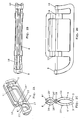
- FIGS 1 A to 1 D show the carriage according to the invention in the unfolded state of use.
- the carriage includes two carriage halves 1, 2 which are mirror-inverted to each other.
- Each carriage half 1,2 consists of a one-piece plastic part, which has a runner portion 3, at its front and rear end in a front transverse web 4 and a rear crosspiece 5 merges, and at the distance from the transverse webs 4 and 5 also spaced apart scissor-like webs 6, 7 are attached, which extend at their free ends by a longitudinal direction of the carriage Wegsteg 8 are connected.
- the transverse webs 4, 5 of the two carriage halves 1, 2 are provided at their free ends in each case with one or more eyelets or hinges 9, 10.
- the transverse webs 4 and 5 of a carriage half 1, each with an eyelet 9 and 10 may be provided, while the transverse webs 4 'and 5' of the other carriage half 2 are also provided with one eyelet, which is axially offset so that the two Eyelets each abut a loop-shaped joint portion to each other.
- each transverse web 4, 4 'and 5, 5' of the two carriage halves 1 and 2 may be provided with a plurality of mutually offset eyelets 9 and 10, which are mutually arranged one behind the other.
- the approximately S-shaped, scissor-shaped webs 6 and 7 each consist of a lower portion 10 and 11, which terminate in the eyelets 9 and 10 corresponding eyelets 13 and 14, and in each case an upper, located on the other carriage side section 15 and 16th ,
- the scissor-like webs 11 and 12 of the two carriage halves 1 and 2 are shaped so that a portion 16 of the upper portion of the scissor-like webs 6 and 7 rests flat on a portion 17 of the lower portion 11 of the scissor-like webs 6 and 7, when the Carriage is in the unfolded position of use. That is, on both sides of the eye-shaped joint portions 13 and 14, the scissor-like webs of the two carriage halves 1 and 2 are smoothly against each other, preferably with flat surfaces or with coincident curved surfaces, whereby the carriage is very stable.
- a cross-sectionally circular connecting rod or a connecting tube 18 which may or may project slightly beyond the outer eyelets 9 and 10 and may be secured there for example by a cap of larger diameter.
- a seat member 19 is stretched in the form of a cloth when the carriage is opened.
- the two right-hand scissor-type webs are denoted by 6 and 7, while the associated webs of the other half-carriage are designated 6 'and 7'. Accordingly, the lower and upper portions are denoted by 11, 15 and 11 'and 15'.
- FIGS. 2A to 2D which show the carriage in the folded state, can be seen that the space requirement of the folded carriage is much smaller, since its width at substantially adjacent runner sections 3 and 3 'and adjacent seat webs 8 and 8' minimal is.
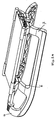
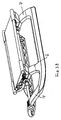
- FIGS 3 and 4 show another embodiment of the carriage in which the rear transverse webs 5 and 5 'of the first embodiment are omitted. Accordingly, this carriage contains only the front transverse webs 4 and the scissor-like webs 6 and 7.
- FIGS 5, 6 and 7 show the locking mechanism of the two hinge portions of the scissor-shaped transverse webs 6 and 7.
- the connecting rod 18 each have a locking sleeve 20 is fixedly connected, on which a locking element 21 is fixed, which has two diametrically arranged, radially projecting locking pin 22 .
- the hinge-like joint sections 23 and 24 of the associated scissor-type webs 6 or 7 of the two carriage halves are seated axially adjacent one another on the locking sleeve.
- the hinge-like portions 23 and 24 respectively include an inner eyelet-shaped or tubular portion 25, 26 and lamellar reinforcing rings 27 and 28 formed thereon.
- the locking pins 22 of the locking sleeve 20 sit in bag-like receiving pockets 29 of the hinge-like joint portion 23, so that the hinge-like joint portion 23 can rotate only together with the locking sleeve 20 and the connecting rod 18.
- the locking sleeve 20 is biased by a coil spring 30 in the direction of the other hinge-like joint portion 24, wherein the coil spring 30 is supported on the one hand on the lateral flanks of the locking pin 22 and on the other hand on an annular shoulder 31 of the hinge-like joint portion 23.
- a circumferential annular end wall 32 of the hinge-like joint portion 24 closes the outlet openings of the receiving spaces 29 of the locking pin 22 until two recesses in the annular end wall 32 are aligned with the outlet openings of the receiving spaces 29, so that the locking pin 22 with its front portion into corresponding receiving spaces 33 of hinge-like joint portion 24 can enter 34 until it abuts against the boundary walls.
- the two hinge-like hinge portions 23, 24 of the scissor-shaped webs are locked against each other, so that the carriage can not be folded.
- the locking position is shown in FIG.
- the unfolded state of use of the carriage is thus automatically secured by the releasable locking mechanism.
Landscapes
- Engineering & Computer Science (AREA)
- Chemical & Material Sciences (AREA)
- Combustion & Propulsion (AREA)
- Transportation (AREA)
- Mechanical Engineering (AREA)
- Purses, Travelling Bags, Baskets, Or Suitcases (AREA)
- Carriages For Children, Sleds, And Other Hand-Operated Vehicles (AREA)
Abstract
Der Schlitten ist aus zwei Schlittenhälften zusammengesetzt, die über Scharniereinrichtungen derart gelenkig miteinander verbunden sind, daß der Schlitten um seine Längsmittelachse zusammenklappbar ist. Im aufgeklappten Zustand liegt jeweils ein oberer Abschnitt eines scherenförmigen Steges mit seiner Unterseite auf der Oberseite des zugeordneten anderen scherenförmigen Steges auf. Durch diese flächige Auflage der scherenförmigen Stege aufeinander ist der Schlitten sehr stabil. Der aufgeklappte Gebrauchszustand des Schlittens wird durch den lösbaren Verriegelungsmechanismus automatisch gesichert.The carriage is composed of two carriage halves, which are hingedly connected to each other via hinge means, that the carriage is collapsible about its longitudinal central axis. In the unfolded state is in each case an upper portion of a scissor-shaped web with its underside on top of the associated other scissor-shaped web. By this two-dimensional edition of the scissor-shaped webs on each other, the carriage is very stable. The unfolded state of use of the carriage is automatically secured by the releasable locking mechanism.
Description
Die Erfindung betrifft einen Schlitten gemäß dem Oberbegriff des Patentanspruchs 1.The invention relates to a carriage according to the preamble of
Ein herkömmlicher Schlitten hat in Folge seiner querschnittlichen Rechteckform einen beträchtlichen Platzbedarf, so daß er beispielsweise in vielen Fällen in dem Kofferraum eines Kraftfahrzeugs zusammen mit anderen Gepäckstücken nicht unterbringbar ist und häufig auf einem Gepäckträger befestigt werden muß. Wenn ein solcher Schlitten in bestimmten Situationen getragen werden muß, kann dies vor allem kleineren Kindern erhebliche Schwierigkeiten bereiten.A conventional carriage has a considerable space requirement as a result of its cross-sectional rectangular shape, so that it can not be accommodated in many cases in the trunk of a motor vehicle together with other items of luggage and must often be mounted on a luggage rack. If such a sled needs to be carried in certain situations, it can be particularly difficult for smaller children.
Der vorliegenden Erfindung liegt die Aufgabe zugrunde, einen Schlitten anzugeben, dessen Platzbedarf beträchtlich verringerbar ist und der leichter tragbar ist. Außerdem soll sichergestellt sein, daß der Schlitten im aufgeklappten Gebrauchszustand die erforderliche Stabilität hat, um den einwirkenden Kräften Stand zu halten und den aufgeklappten Zustand sicher beizubehalten.The present invention has for its object to provide a carriage whose footprint is considerably reduced and easier to carry. In addition, it should be ensured that the carriage in the unfolded condition of use has the required stability to keep up the forces acting and safely maintain the unfolded state.
Diese Aufgabe wird erfindungsgemäß durch die Merkmale des Patentanspruchs 1 gelöst.This object is achieved by the features of
Die Erfindung sieht vor, daß der Schlitten aus zwei Schlittenhälften zusammengesetzt ist, die über Scharniereinrichtungen derart gelenkig miteinander verbunden sind, daß der Schlitten um seine Längsmittelachse zusammenklappbar ist.The invention provides that the carriage is composed of two carriage halves, which are hingedly connected to each other via hinge means, that the carriage is collapsible about its longitudinal central axis.
Dabei ist mit Vorzug vorgesehen, daß die Schlittenhälften jeweils einen Kufenabschnitt enthalten, der in einen vorderen Quersteg übergeht, der an seinem freien Ende mit einem ösenförmigen bzw. scharnierartigen Gelenkabschnitt versehen ist, und zwei weitere an dem Kufenabschnitt angesetzte scherenförmig ausgebildete Querstege, die an ihren Enden jeweils durch einen in Längsrichtung verlaufenden Sitzsteg verbunden sind, an dem ein flexibles Sitzelement befestigt ist, und daß die scherenförmigen Stege jeweils an einer Zwischenposition mit ösenförmigen bzw. scharnierartigen Gelenkabschnitten versehen sind. Das Sitzelement ist bevorzugt ein Tuch, das im aufgeklappten Gebrauchszustand des Schlittens zwischen den beiden Sitzstegen gespannt ist.It is provided with preference that the carriage halves each contain a runner section, which merges into a front transverse web, which is provided at its free end with a loop-shaped or hinge-like joint portion, and two further attached to the runner section scissor-shaped transverse webs, at their Ends are each connected by a longitudinally extending seat web, on which a flexible seat member is fixed, and that the scissor-shaped webs are each provided at an intermediate position with eye-shaped or hinge-like hinge portions. The seat element is preferably a cloth, which is stretched in the unfolded state of use of the carriage between the two seat webs.
Weiter ist vorgesehen, daß alle scharnierartigen Gelenkabschnitte miteinander fluchten und daß ein querschnittlich bevorzugt kreisrunder Verbindungsstab durch die Gelenkabschnitte verläuft. Dieser Verbindungsstab, der bevorzugt eine Rohrform hat, steht zweckmäßigerweise ein wenig über die vorderen und hinteren Ösenabschnitte vor und kann beispielsweise mit einer Befestigungskappe größeren Durchmessers versehen sein, wobei diese Kappen fest an den beiden Enden des Verbindungsstabes angebracht sind. Es können auch andere Mittel vorgesehen sein, die den Verbindungsstab sicher in seiner Einbaulage fixieren.It is further provided that all hinge-like joint portions are aligned with each other and that a cross-sectionally preferably circular connecting rod extends through the joint portions. This connecting rod, which preferably has a tubular shape, is expediently slightly above the front and rear eyelet sections and may for example be provided with a mounting cap of larger diameter, these caps are fixedly attached to the two ends of the connecting rod. It can also be provided other means that securely fix the connecting rod in its installed position.
Anstatt eines einzigen durchgehenden Verbindungsstabs oder Verbindungsrohres können auch an jedem Gelenkabschnitt zugehörige kurze Scharnierstifte vorgesehen sein.Instead of a single continuous connecting rod or connecting tube associated short hinge pins may be provided at each joint portion.
Mit besonderem Vorteil ist vorgesehen, daß jeweils ein oberer Abschnitt der beiden scherenförmigen Stege mit seiner Unterseite im aufgeklappten Zustand des Schlittens auf der Oberseite des unteren Abschnitts des jeweils zugeordneten anderen scherenförmigen Steges aufliegt, wobei in diesem Zustand - wie oben erwähnt - das Sitztuch gespannt ist. Durch diese flächige Auflage der scherenförmigen Stege auf einander ist der Schlitten sehr stabil.With particular advantage, it is provided that in each case an upper portion of the two scissor-shaped webs rests with its underside in the unfolded state of the carriage on the upper side of the lower portion of the respectively associated other scissor-shaped web, wherein in this state - As mentioned above - the seat is stretched. By this two-dimensional edition of the scissor-shaped webs on each other, the carriage is very stable.
Mit großem Vorteil wird ferner vorgeschlagen, daß der Schlitten im aufgeklappten Gebrauchszustand durch einen lösbaren Verriegelungsmechanismus gesichert ist. Dabei ist bevorzugt, daß der Verriegelungsmechanismus eine in axialer Richtung verschiebliche Verriegelungshülse enthält, die die scharnierartigen Gelenkabschnitte wenigstens eines Paares der scherenförmigen Stege im aufgeklappten Zustand des Schlittens verriegelt. Zweckmäßigerweise sind beide Scharnierbereiche der scherenförmigen Querstäbe mit einem derartigen Verriegelungsmechanismus versehen.With great advantage is also proposed that the carriage is secured in the unfolded condition of use by a releasable locking mechanism. It is preferred that the locking mechanism includes a displaceable in the axial direction locking sleeve which locks the hinge-like hinge portions of at least one pair of scissor-shaped webs in the unfolded state of the carriage. Conveniently, both hinge portions of the scissor-shaped transverse rods are provided with such a locking mechanism.
Die Verriegelungshülse kann dabei wenigstens einen nach außen weisenden Vorsprung aufweisen, der in einem seitlich den Vorsprung mit geringem Spiel umfassenden Aufnahmeraum eines der scharnierartigen Gelenkabschnitte sitzt, wobei dieser Aufnahmeraum zu dem angrenzenden anderen scharnierartigen Gelenkabschnitt hin offen ist, und daß der andere scharnierartige Gelenkabschnitt eine umlaufende stirnseitige Begrenzungswand mit einer Aussparung aufweist, durch die ein axialer Abschnitt des Vorsprungs in einen entsprechenden Aufnahmeraum eintreten kann. Bevorzugt hat die Verriegelungshülse zwei derartige, diametral gegenüberliegende Vorsprünge, die radial nach außen von der Verriegelungshülse abstehen.The locking sleeve can have at least one outwardly facing projection which sits in a side of the projection with little clearance comprehensive receiving space of one of the hinge-like hinge portions, said receiving space to the adjacent other hinge-like hinge portion is open, and that the other hinge-like hinge portion is a circumferential Front boundary wall having a recess through which an axial portion of the projection can enter into a corresponding receiving space. Preferably, the locking sleeve has two such diametrically opposite projections which project radially outward from the locking sleeve.
Weiter ist vorgesehen, daß die Verriegelungshülse durch eine Federeinrichtung, bevorzugt eine die Verriegelungshülse umgebende Schraubenfeder, in die Verriegelungsrichtung vorgespannt ist.It is further provided that the locking sleeve is biased by a spring device, preferably a coil spring surrounding the locking sleeve, in the locking direction.
Die Verriegelungshülse ist fest mit dem Verbindungsstab verbunden, so daß sie durch Verschieben des Verbindungsstabes entgegen der Verriegelungsrichtung wieder in die Freigabestellung verschiebbar ist, in der die Verriegelungshülse aus dem einen scharnierartigen Gelenkabschnitt wieder austritt.The locking sleeve is firmly connected to the connecting rod, so that it is displaceable by displacing the connecting rod against the locking direction back into the release position, in which the locking sleeve from the one hinge-like hinge section exits again.
Die Stege der beiden Schlittenhälften haben zweckmäßigerweise querschnittlich eine langgestreckte Rechteckform. Die beiden Schlittenhälften bestehen bevorzugt aus Kunststoff und sind einstückig hergestellt, so daß der aus wenigen Teilen zusammengesetzte Schlitten mit verhältnismäßig geringen Kosten herstellbar ist.The webs of the two carriage halves have expediently cross-section an elongated rectangular shape. The two carriage halves are preferably made of plastic and are made in one piece, so that the composite of a few parts carriage can be produced at relatively low cost.
Weitere Einzelheiten der Erfindung ergeben sich aus der nachfolgenden Beschreibung zweier bevorzugter Ausführungsformen sowie anhand der Zeichnungen. Dabei zeigen:
- Figuren 1A bis 1D
- eine erste Ausführungsform des Schlittens in einer perspektivischen Ansicht, einer Draufsicht, einer vorderen Stirnansicht und einer Seitenansicht;
- Figuren 2A bis 2D
- den Schlitten der
Figur 1 in entsprechenden Darstellungen im zusammengeklappten Zustand; - Figuren 3A und 3B
- eine zweite Ausführungsform des Schlittens in perspektivischen Ansichten schräg von hinten und schräg von vorne;
- Figuren 4A und 4B
- den Schlitten der
Figur 3 im zusammengeklappten Zustand in zwei perspektivischen Ansichten; Figur 5- eine teilweise geschnittene Darstellung der Scharniere der scherenförmigen Querstege, im entriegelten Zustand der Kufen;
Figur 6- den verriegelten Zustand der Kufen im aufgeklappten Gebrauchszustand des Schlittens und
Figur 7- eine perspektivische Darstellung der Verriegelungshülse der Scharniere.
- Figures 1A to 1D
- a first embodiment of the carriage in a perspective view, a plan view, a front end view and a side view;
- FIGS. 2A to 2D
- the carriage of Figure 1 in corresponding representations in the folded state;
- FIGS. 3A and 3B
- a second embodiment of the carriage in perspective views obliquely from behind and obliquely from the front;
- FIGS. 4A and 4B
- the carriage of Figure 3 in the folded state in two perspective views;
- FIG. 5
- a partially sectioned view of the hinges of the scissor-shaped transverse webs, in the unlocked state of the runners;
- FIG. 6
- the locked state of the skids in the unfolded state of use of the carriage and
- FIG. 7
- a perspective view of the locking sleeve of the hinges.
Die Figuren 1 A bis 1 D zeigen den erfindungsgemäßen Schlitten im aufgeklappten Gebrauchszustand. Der Schlitten enthält zwei Schlittenhälften 1, 2 die spiegelverkehrt zueinander ausgebildet sind. Jede Schlittenhälfte 1,2 besteht aus einem einstückigen Kunststoffteil, das einen Kufenabschnitt 3 aufweist, der an seinem vorderen und hinteren Ende in einen vorderen Quersteg 4 und einen hinteren Quersteg 5 übergeht, und an dem im Abstand von den Querstegen 4 und 5 ebenfalls voneinander beabstandete scherenförmige Stege 6, 7 angesetzt sind, die an ihren freien Enden durch einen in Längsrichtung des Schlittens verlaufenden Sitzsteg 8 verbunden sind.Figures 1 A to 1 D show the carriage according to the invention in the unfolded state of use. The carriage includes two
Die Querstege 4, 5 der beiden Schlittenhälften 1, 2 sind an ihren freien Enden jeweils mit einer oder mehreren Ösen bzw. Scharnieren 9, 10 versehen. Beispielsweise können die Querstege 4 und 5 der einen Schlittenhälfte 1 mit jeweils einer Öse 9 und 10 versehen sein, während die Querstege 4' und 5' der anderen Schlittenhälfte 2 ebenfalls mit je einer Öse versehen sind, die derart axial versetzt ist, daß die beiden Ösen je eines ösenförmigen Gelenkabschnitts aneinander anliegen. Natürlich kann jeder Quersteg 4, 4' und 5, 5' der beiden Schlittenhälften 1 und 2 auch mit mehreren versetzt zueinander angeordneten Ösen 9 und 10 versehen sein, die wechselseitig hintereinander angeordnet sind.The
Die etwa S-förmigen, scherenförmigen Stege 6 und 7 bestehen jeweils aus einem unteren Abschnitt 10 bzw. 11, die in den Ösen 9 und 10 entsprechenden Ösen 13 und 14 enden, sowie jeweils einem oberen, an der anderen Schlittenseite befindlichen Abschnitt 15 und 16.The approximately S-shaped, scissor-
Dabei sind die scherenförmigen Stege 11 und 12 der beiden Schlittenhälften 1 und 2 so geformt, daß ein Bereich 16 des oberen Abschnitts der scherenförmigen Stege 6 und 7 flächig auf einem Bereich 17 des unteren Abschnitts 11 der scherenförmigen Stege 6 und 7 aufliegt, wenn sich der Schlitten in der aufgeklappten Gebrauchsstellung befindet. Das heißt, zu beiden Seiten der ösenförmigen Gelenkabschnitte 13 und 14 liegen die scherenförmigen Stege der beiden Schlittenhälften 1 und 2 vorzugsweise mit ebenen Flächen oder mit übereinstimmend gekrümmten Flächen glatt aneinander an, wodurch der Schlitten sehr stabil ist.The scissor-
Durch die Ösen 9, 13, 14 und 10 verläuft ein im Querschnitt kreisförmiger Verbindungsstab bzw. ein Verbindungsrohr 18, der bzw. das ein wenig über die äußeren Ösen 9 und 10 vorstehen kann und dort beispielsweise durch eine Kappe größeren Durchmessers gesichert sein kann.Through the
Zwischen den Sitzstegen 8 ist ein Sitzelement 19 in Form eines Tuches gespannt, wenn der Schlitten aufgeklappt ist.Between the
In den Figuren 2A und 2C sind die beiden rechten scherenförmigen Stege mit 6 und 7 bezeichnet, während die zugehörigen Stege der anderen Schlittenhälfte mit 6' und 7' bezeichnet sind. Entsprechend sind die unteren und oberen Abschnitte mit 11, 15 und 11' und 15' bezeichnet.In FIGS. 2A and 2C, the two right-hand scissor-type webs are denoted by 6 and 7, while the associated webs of the other half-carriage are designated 6 'and 7'. Accordingly, the lower and upper portions are denoted by 11, 15 and 11 'and 15'.
Die Figuren 2A bis 2D, die den Schlitten im zusammengeklappten Zustand zeigen, lassen erkennen, daß der Platzbedarf des zusammengeklappten Schlittens sehr viel kleiner ist, da seine Breite bei im wesentlichen aneinander anliegenden Kufenabschnitten 3 und 3' sowie aneinander anliegenden Sitzstegen 8 und 8' minimal ist.Figures 2A to 2D, which show the carriage in the folded state, can be seen that the space requirement of the folded carriage is much smaller, since its width at substantially
Die Figuren 3 und 4 zeigen eine andere Ausführungsform des Schlittens, bei der die hinteren Querstege 5 und 5' der ersten Ausführungsform weggelassen sind. Dieser Schlitten enthält demnach nur die vorderen Querstege 4 sowie die scherenförmigen Stege 6 und 7.Figures 3 and 4 show another embodiment of the carriage in which the rear
Die Figuren 5, 6 und 7 zeigen den Verriegelungsmechanismus der beiden Scharnierbereiche der scherenförmigen Querstege 6 und 7. Mit dem Verbindungsstab 18 ist jeweils eine Verriegelungshülse 20 fest verbunden, auf der ein Verriegelungselement 21 befestigt ist, das zwei diametral angeordnete, radial abstehende Verriegelungszapfen 22 aufweist. Auf der Verriegelungshülse sitzen axial aneinander anliegend die scharnierartigen Gelenkabschnitte 23 und 24 der zusammengehörigenden scherenförmigen Stege 6 oder 7 der beiden Schlittenhälften. Die scharnierartigen Abschnitte 23 und 24 enthalten jeweils einen inneren ösenförmigen bzw. rohrförmigen Abschnitt 25, 26 und daran angeformte lamellenartige Verstärkungsringe 27 und 28.Figures 5, 6 and 7 show the locking mechanism of the two hinge portions of the scissor-shaped
Die Verriegelungszapfen 22 der Verriegelungshülse 20 sitzen in sackartigen Aufnahmetaschen 29 des scharnierartigen Gelenkabschnitts 23, so daß sich der scharnierartige Gelenkabschnitt 23 stets nur gemeinsam mit der Verriegelungshülse 20 und dem Verbindungsstab 18 drehen kann. Die Verriegelungshülse 20 ist durch eine Schraubenfeder 30 in Richtung des anderen scharnierartigen Gelenkabschnitts 24 vorgespannt, wobei sich die Schraubenfeder 30 einerseits an den seitlichen Flanken der Verriegelungszapfen 22 und andererseits an einer Ringschulter 31 des scharnierartigen Gelenkabschnitts 23 abstützt.The locking pins 22 of the locking
Eine umlaufende ringförmige Stirnwand 32 des scharnierartigen Gelenkabschnitts 24 verschließt solange die Austrittsöffnungen der Aufnahmeräume 29 der Verriegelungszapfen 22, bis zwei Aussparungen in der ringförmigen Stirnwand 32 mit den Austrittöffnungen der Aufnahmeräume 29 fluchten, so daß die Verriegelungszapfen 22 mit ihrem vorderen Abschnitt in entsprechende Aufnahmeräume 33 des scharnierartigen Gelenkabschnitts 24 bis zur Anlage an deren Begrenzungswände 34 eintreten können. Wenn dies geschieht, sind die beiden scharnierartigen Gelenkabschnitte 23, 24 der scherenförmigen Stege gegeneinander verriegelt, so daß der Schlitten nicht zusammengeklappt werden kann. Die Verriegelungsstellung ist in Figur 6 dargestellt.A circumferential annular end wall 32 of the hinge-like
Die Verriegelung wird dadurch wieder freigegeben, daß der Verbindungsstab 18 mit der Verriegelungshülse 20 gegen die Kraft der Feder 30 bis zur Anlage an die Begrenzungswand 35 des Aufnahmeraums 29 zurückgedrückt wird, wodurch die scharnierartigen Gelenkabschnitte wieder gegeneinander drehbar werden.The lock is released again that the connecting
Der aufgeklappte Gebrauchszustand des Schlittens wird durch den lösbaren Verriegelungsmechanismus demnach automatisch gesichert.The unfolded state of use of the carriage is thus automatically secured by the releasable locking mechanism.
Claims (9)
dadurch gekennzeichnet,
daß der Schlitten aus zwei Schlittenhälften (1, 2) zusammengesetzt ist, die über Scharniereinrichtungen (9, 13, 14, 10) derart gelenkig miteinander verbunden sind, daß der Schlitten um seine Längsmittelachse zusammenklappbar ist.Carriage,
characterized,
in that the carriage is composed of two carriage halves (1, 2) which are hingedly connected to one another via hinge devices (9, 13, 14, 10) in such a way that the carriage can be folded about its longitudinal central axis.
dadurch gekennzeichnet,
daß die Schlittenhälften (1, 2) jeweils einen Kufenabschnitt (3, 3'), der in einen vorderen Quersteg (4, 4') übergeht, der an seinem freien Ende mit einem ösenförmigen Gelenkabschnitt (9) versehen ist, und an dem Kufenabschnitt angesetzte scherenförmige Stege (6, 6'; 7, 7') aufweisen, die an ihren freien Enden durch jeweils einen in Längsrichtung verlaufenden Sitzsteg (8, 8') verbunden sind, an denen ein flexibles Sitzelement (19) befestigt ist, wobei die scherenförmigen Stege jeweils an einer Zwischenposition mit ösenförmigen bzw. scharnierartigen Gelenkabschnitten (13, 14) versehen sind.Carriage according to claim 1,
characterized,
in that the carriage halves (1, 2) each have a runner section (3, 3 ') which merges into a front transverse web (4, 4') provided at its free end with a loop-shaped joint section (9) and at the runner section arranged scissor-like webs (6, 6 ', 7, 7'), which are connected at their free ends by a respective longitudinally extending seat web (8, 8 ') to which a flexible seat member (19) is attached, wherein the Scissor-shaped webs are each provided at an intermediate position with eye-shaped or hinge-like joint portions (13, 14).
dadurch gekennzeichnet,
daß alle scharnierartigen Gelenkabschnitte (9, 13, 14, 10) miteinander fluchten und daß ein querschnittlich kreisrunder Verbindungsstab (18) durch die Gelenkabschnitte verläuft.Carriage according to claim 1 or 2,
characterized,
in that all hinge-like joint sections (9, 13, 14, 10) are aligned with one another and that a cross-sectionally circular connecting rod (18) extends through the joint sections.
dadurch gekennzeichnet, daß jeweils ein oberer Abschnitt (16, 16') eines scherenförmigen Steges (6, 6'; 7, 7'),mit seiner Unterseite im aufgeklappten Zustand des Schlittens auf der Oberseite (17, 17') des zugeordneten anderen scherenförmigen Steges aufliegt.Carriage according to one of claims 1 to 3,
characterized in that in each case an upper portion (16, 16 ') of a scissors-shaped web (6, 6'; 7, 7 '), with its underside in the unfolded state of the carriage on the upper side (17, 17') of the associated other scissor-shaped Bridge rests.
dadurch gekennzeichnet,
daß der aufgeklappte Zustand des Schlittens durch einen lösbaren Verriegelungsmechanismus gesichert ist, wobei der Verriegelungsmechanismus eine in axialer Richtung verschiebliche Verriegelungshülse (20) enthält, die die scharnierartigen Gelenkabschnitte (23,24) wenigstens eines Paares scherenförmiger Stege (6 oder 7) im aufgeklappten Zustand des Schlittens verriegelt.Carriage according to one of claims 1 to 4,
characterized,
that the unfolded state of the carriage is secured by a releasable locking mechanism, the locking mechanism comprising an axially displaceable locking sleeve (20) comprising the hinged hinge portions (23, 24) of at least one pair of scissor-type webs (6 or 7) in the unfolded state of the Schlitten locks.
dadurch gekennzeichnet,
daß die Verriegelungshülse (20) wenigstens einen nach außen weisenden Vorsprung (22) aufweist, der in einem Aufnahmeraum (29) eines scharnierartigen Gelenkabschnitts (23) sitzt, wobei der Aufnahmeraum (29) zu dem angrenzenden anderen scharnierartigen Gelenkabschnitt (24) hin offen ist, und daß der andere scharnierartige Gelenkabschnitt (24) eine stirnseitige Begrenzungswand (32) mit einer Aussparung aufweist, durch die ein axialer Abschnitt des Vorsprungs (22) in einen entsprechenden Aufnahmeraum (33) eintreten kann.Carriage according to claim 5,
characterized,
in that the locking sleeve (20) has at least one outwardly facing projection (22) which sits in a receiving space (29) of a hinge-like joint portion (23), the receiving space (29) being open to the adjacent other hinge-like joint portion (24) and in that the other hinge-like hinge portion (24) has an end wall (32) with a recess through which an axial portion of the projection (22) can enter into a corresponding receiving space (33).
dadurch gekennzeichnet,
daß die Verriegelungshülse (20) durch eine Federreinrichtung (30) in die Verriegelungsrichtung vorgespannt ist.Carriage according to claim 5 or 6,
characterized,
that the locking sleeve (20) is biased by a spring device (30) in the locking direction.
dadurch gekennzeichnet,
daß die Verriegelungshülse (20) fest mit dem Verbindungsstab (18) verbunden ist.Carriage according to claims 5 to 7,
characterized,
that the locking sleeve (20) is fixedly connected to the connecting rod (18).
dadurch gekennzeichnet,
daß die beiden Schlittenhälften jeweils (1, 2) einstückig aus Kunststoff hergestellt sind.Carriage according to one of claims 1 to 8,
characterized,
that the two carriage halves (1, 2) are each made in one piece from plastic.
Priority Applications (2)
| Application Number | Priority Date | Filing Date | Title |
|---|---|---|---|
| NO20054159A NO325700B1 (en) | 2004-09-09 | 2005-09-07 | toboggan |
| US11/222,252 US20060049589A1 (en) | 2004-09-09 | 2005-09-08 | Sled |
Applications Claiming Priority (1)
| Application Number | Priority Date | Filing Date | Title |
|---|---|---|---|
| DE200410043582 DE102004043582A1 (en) | 2004-09-09 | 2004-09-09 | carriage |
Publications (2)
| Publication Number | Publication Date |
|---|---|
| EP1634794A2 true EP1634794A2 (en) | 2006-03-15 |
| EP1634794A3 EP1634794A3 (en) | 2007-10-24 |
Family
ID=35447183
Family Applications (1)
| Application Number | Title | Priority Date | Filing Date |
|---|---|---|---|
| EP05012822A Withdrawn EP1634794A3 (en) | 2004-09-09 | 2005-06-15 | Sledge |
Country Status (2)
| Country | Link |
|---|---|
| EP (1) | EP1634794A3 (en) |
| DE (1) | DE102004043582A1 (en) |
Cited By (1)
| Publication number | Priority date | Publication date | Assignee | Title |
|---|---|---|---|---|
| PL131133U1 (en) * | 2022-12-08 | 2023-10-09 | Kunert Marcin Przedsiębiorstwo Produkcyjno-Handlowo-Usługowe Kunert | Folding sled |
Family Cites Families (7)
| Publication number | Priority date | Publication date | Assignee | Title |
|---|---|---|---|---|
| US68534A (en) * | 1867-09-03 | Jacob shaaber | ||
| DE31866C (en) * | W. SINGER in Berlin SW., Gneisenaustrafse 4 | Foldable children's sledge | ||
| CH33164A (en) * | 1905-08-29 | 1906-03-15 | Christian Metzger | Collapsible sleigh |
| US3365209A (en) * | 1965-07-27 | 1968-01-23 | Fischer Benedikt | Collapsible sled |
| YU32984A (en) * | 1984-02-22 | 1987-02-28 | Djordje Rabatic | Folding sledge |
| US4648611A (en) * | 1985-05-30 | 1987-03-10 | Kekich Ivica J | Foldable sled or toboggan |
| CA2170173A1 (en) * | 1996-02-23 | 1997-08-24 | Derek Parker | Sled |
-
2004
- 2004-09-09 DE DE200410043582 patent/DE102004043582A1/en not_active Withdrawn
-
2005
- 2005-06-15 EP EP05012822A patent/EP1634794A3/en not_active Withdrawn
Cited By (2)
| Publication number | Priority date | Publication date | Assignee | Title |
|---|---|---|---|---|
| PL131133U1 (en) * | 2022-12-08 | 2023-10-09 | Kunert Marcin Przedsiębiorstwo Produkcyjno-Handlowo-Usługowe Kunert | Folding sled |
| PL73843Y1 (en) * | 2022-12-08 | 2025-03-24 | Kunert Marcin Przed Produkcyjno Handlowo Uslugowe Kunert | Folding sled |
Also Published As
| Publication number | Publication date |
|---|---|
| DE102004043582A1 (en) | 2006-03-30 |
| EP1634794A3 (en) | 2007-10-24 |
Similar Documents
| Publication | Publication Date | Title |
|---|---|---|
| EP0964976B1 (en) | Folding ladder | |
| DE69926041T2 (en) | Locking device for collapsible stroller | |
| DE69516576T2 (en) | Device for inner tent or tent carrier frames | |
| DE69027782T2 (en) | SCAFFOLDING COUPLING | |
| DE102007014992B4 (en) | Foldable carriage assembly for a paint spray pump | |
| EP3634170B1 (en) | Clamping device for a longitudinally adjustable pole | |
| EP1388309B1 (en) | Joint, especially for daybeds | |
| DE8227212U1 (en) | Divisible stretcher | |
| EP3362372B1 (en) | Pallet container | |
| DE29911334U1 (en) | Folding device for golf carts | |
| EP1138849A2 (en) | Tube element | |
| DE2159881A1 (en) | ROLLER | |
| DE19538080A1 (en) | Transporting device for small boats, surfboards etc. | |
| DE29923174U1 (en) | Split vehicle backrest | |
| DE102006027258B4 (en) | Side tab for chain links of an energy chain | |
| DE3717310C1 (en) | Bolt lock | |
| EP1125800B1 (en) | Restraining sheet for the interior of a motor vehicle | |
| DE102004043582A1 (en) | carriage | |
| DE69501903T2 (en) | Step | |
| DE29504755U1 (en) | Adjustable joint for pushchairs | |
| DE10007613C1 (en) | Vehicle interior retaining net has folding holding rod with two sections which are locked together by sliding sleeve over their hinge joint when they are in alignment with each other, for easy use | |
| DE10113136A1 (en) | Folding step for caravan or motor home has spacing profiles with at least one channel extending along it and with which interact screws passing through holes in end elements in hinge arms and in suspension profiles | |
| DE3780962T2 (en) | GOLF CART OR CARRIAGE. | |
| DE10043348A1 (en) | Safety rod to fix position of folded-up part of vehicle seat consists of under-part and over-part linked by lockable pivot | |
| DE10206042B4 (en) | Device for releasably fixing a pivotable spar in a child or doll carriage |
Legal Events
| Date | Code | Title | Description |
|---|---|---|---|
| PUAI | Public reference made under article 153(3) epc to a published international application that has entered the european phase |
Free format text: ORIGINAL CODE: 0009012 |
|
| AK | Designated contracting states |
Kind code of ref document: A2 Designated state(s): AT BE BG CH CY CZ DE DK EE ES FI FR GB GR HU IE IS IT LI LT LU MC NL PL PT RO SE SI SK TR |
|
| AX | Request for extension of the european patent |
Extension state: AL BA HR LV MK YU |
|
| PUAL | Search report despatched |
Free format text: ORIGINAL CODE: 0009013 |
|
| AK | Designated contracting states |
Kind code of ref document: A3 Designated state(s): AT BE BG CH CY CZ DE DK EE ES FI FR GB GR HU IE IS IT LI LT LU MC NL PL PT RO SE SI SK TR |
|
| AX | Request for extension of the european patent |
Extension state: AL BA HR LV MK YU |
|
| AKX | Designation fees paid | ||
| STAA | Information on the status of an ep patent application or granted ep patent |
Free format text: STATUS: THE APPLICATION IS DEEMED TO BE WITHDRAWN |
|
| 18D | Application deemed to be withdrawn |
Effective date: 20080425 |
|
| REG | Reference to a national code |
Ref country code: DE Ref legal event code: 8566 |