EP1634794A2 - Luge - Google Patents
Luge Download PDFInfo
- Publication number
- EP1634794A2 EP1634794A2 EP05012822A EP05012822A EP1634794A2 EP 1634794 A2 EP1634794 A2 EP 1634794A2 EP 05012822 A EP05012822 A EP 05012822A EP 05012822 A EP05012822 A EP 05012822A EP 1634794 A2 EP1634794 A2 EP 1634794A2
- Authority
- EP
- European Patent Office
- Prior art keywords
- carriage
- hinge
- scissor
- shaped
- webs
- Prior art date
- Legal status (The legal status is an assumption and is not a legal conclusion. Google has not performed a legal analysis and makes no representation as to the accuracy of the status listed.)
- Withdrawn
Links
Images



Classifications
-
- B—PERFORMING OPERATIONS; TRANSPORTING
- B62—LAND VEHICLES FOR TRAVELLING OTHERWISE THAN ON RAILS
- B62B—HAND-PROPELLED VEHICLES, e.g. HAND CARTS OR PERAMBULATORS; SLEDGES
- B62B13/00—Sledges with runners
- B62B13/16—Collapsible or foldable sledges
Definitions
- the invention relates to a carriage according to the preamble of patent claim 1.
- a conventional carriage has a considerable space requirement as a result of its cross-sectional rectangular shape, so that it can not be accommodated in many cases in the trunk of a motor vehicle together with other items of luggage and must often be mounted on a luggage rack. If such a sled needs to be carried in certain situations, it can be particularly difficult for smaller children.
- the present invention has for its object to provide a carriage whose footprint is considerably reduced and easier to carry. In addition, it should be ensured that the carriage in the unfolded condition of use has the required stability to keep up the forces acting and safely maintain the unfolded state.
- the invention provides that the carriage is composed of two carriage halves, which are hingedly connected to each other via hinge means, that the carriage is collapsible about its longitudinal central axis.
- the carriage halves each contain a runner section, which merges into a front transverse web, which is provided at its free end with a loop-shaped or hinge-like joint portion, and two further attached to the runner section scissor-shaped transverse webs, at their Ends are each connected by a longitudinally extending seat web, on which a flexible seat member is fixed, and that the scissor-shaped webs are each provided at an intermediate position with eye-shaped or hinge-like hinge portions.
- the seat element is preferably a cloth, which is stretched in the unfolded state of use of the carriage between the two seat webs.
- all hinge-like joint portions are aligned with each other and that a cross-sectionally preferably circular connecting rod extends through the joint portions.
- This connecting rod which preferably has a tubular shape, is expediently slightly above the front and rear eyelet sections and may for example be provided with a mounting cap of larger diameter, these caps are fixedly attached to the two ends of the connecting rod. It can also be provided other means that securely fix the connecting rod in its installed position.
- the carriage is secured in the unfolded condition of use by a releasable locking mechanism.
- the locking mechanism includes a displaceable in the axial direction locking sleeve which locks the hinge-like hinge portions of at least one pair of scissor-shaped webs in the unfolded state of the carriage.
- both hinge portions of the scissor-shaped transverse rods are provided with such a locking mechanism.
- the locking sleeve can have at least one outwardly facing projection which sits in a side of the projection with little clearance comprehensive receiving space of one of the hinge-like hinge portions, said receiving space to the adjacent other hinge-like hinge portion is open, and that the other hinge-like hinge portion is a circumferential Front boundary wall having a recess through which an axial portion of the projection can enter into a corresponding receiving space.
- the locking sleeve has two such diametrically opposite projections which project radially outward from the locking sleeve.
- the locking sleeve is biased by a spring device, preferably a coil spring surrounding the locking sleeve, in the locking direction.
- the locking sleeve is firmly connected to the connecting rod, so that it is displaceable by displacing the connecting rod against the locking direction back into the release position, in which the locking sleeve from the one hinge-like hinge section exits again.
- the webs of the two carriage halves have expediently cross-section an elongated rectangular shape.
- the two carriage halves are preferably made of plastic and are made in one piece, so that the composite of a few parts carriage can be produced at relatively low cost.
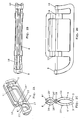
- FIGS 1 A to 1 D show the carriage according to the invention in the unfolded state of use.
- the carriage includes two carriage halves 1, 2 which are mirror-inverted to each other.
- Each carriage half 1,2 consists of a one-piece plastic part, which has a runner portion 3, at its front and rear end in a front transverse web 4 and a rear crosspiece 5 merges, and at the distance from the transverse webs 4 and 5 also spaced apart scissor-like webs 6, 7 are attached, which extend at their free ends by a longitudinal direction of the carriage Wegsteg 8 are connected.
- the transverse webs 4, 5 of the two carriage halves 1, 2 are provided at their free ends in each case with one or more eyelets or hinges 9, 10.
- the transverse webs 4 and 5 of a carriage half 1, each with an eyelet 9 and 10 may be provided, while the transverse webs 4 'and 5' of the other carriage half 2 are also provided with one eyelet, which is axially offset so that the two Eyelets each abut a loop-shaped joint portion to each other.
- each transverse web 4, 4 'and 5, 5' of the two carriage halves 1 and 2 may be provided with a plurality of mutually offset eyelets 9 and 10, which are mutually arranged one behind the other.
- the approximately S-shaped, scissor-shaped webs 6 and 7 each consist of a lower portion 10 and 11, which terminate in the eyelets 9 and 10 corresponding eyelets 13 and 14, and in each case an upper, located on the other carriage side section 15 and 16th ,
- the scissor-like webs 11 and 12 of the two carriage halves 1 and 2 are shaped so that a portion 16 of the upper portion of the scissor-like webs 6 and 7 rests flat on a portion 17 of the lower portion 11 of the scissor-like webs 6 and 7, when the Carriage is in the unfolded position of use. That is, on both sides of the eye-shaped joint portions 13 and 14, the scissor-like webs of the two carriage halves 1 and 2 are smoothly against each other, preferably with flat surfaces or with coincident curved surfaces, whereby the carriage is very stable.
- a cross-sectionally circular connecting rod or a connecting tube 18 which may or may project slightly beyond the outer eyelets 9 and 10 and may be secured there for example by a cap of larger diameter.
- a seat member 19 is stretched in the form of a cloth when the carriage is opened.
- the two right-hand scissor-type webs are denoted by 6 and 7, while the associated webs of the other half-carriage are designated 6 'and 7'. Accordingly, the lower and upper portions are denoted by 11, 15 and 11 'and 15'.
- FIGS. 2A to 2D which show the carriage in the folded state, can be seen that the space requirement of the folded carriage is much smaller, since its width at substantially adjacent runner sections 3 and 3 'and adjacent seat webs 8 and 8' minimal is.
- FIGS 3 and 4 show another embodiment of the carriage in which the rear transverse webs 5 and 5 'of the first embodiment are omitted. Accordingly, this carriage contains only the front transverse webs 4 and the scissor-like webs 6 and 7.
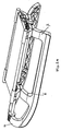
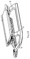
- FIGS 5, 6 and 7 show the locking mechanism of the two hinge portions of the scissor-shaped transverse webs 6 and 7.
- the connecting rod 18 each have a locking sleeve 20 is fixedly connected, on which a locking element 21 is fixed, which has two diametrically arranged, radially projecting locking pin 22 .
- the hinge-like joint sections 23 and 24 of the associated scissor-type webs 6 or 7 of the two carriage halves are seated axially adjacent one another on the locking sleeve.
- the hinge-like portions 23 and 24 respectively include an inner eyelet-shaped or tubular portion 25, 26 and lamellar reinforcing rings 27 and 28 formed thereon.
- the locking pins 22 of the locking sleeve 20 sit in bag-like receiving pockets 29 of the hinge-like joint portion 23, so that the hinge-like joint portion 23 can rotate only together with the locking sleeve 20 and the connecting rod 18.
- the locking sleeve 20 is biased by a coil spring 30 in the direction of the other hinge-like joint portion 24, wherein the coil spring 30 is supported on the one hand on the lateral flanks of the locking pin 22 and on the other hand on an annular shoulder 31 of the hinge-like joint portion 23.
- a circumferential annular end wall 32 of the hinge-like joint portion 24 closes the outlet openings of the receiving spaces 29 of the locking pin 22 until two recesses in the annular end wall 32 are aligned with the outlet openings of the receiving spaces 29, so that the locking pin 22 with its front portion into corresponding receiving spaces 33 of hinge-like joint portion 24 can enter 34 until it abuts against the boundary walls.
- the two hinge-like hinge portions 23, 24 of the scissor-shaped webs are locked against each other, so that the carriage can not be folded.
- the locking position is shown in FIG.
- the unfolded state of use of the carriage is thus automatically secured by the releasable locking mechanism.
Landscapes
- Engineering & Computer Science (AREA)
- Chemical & Material Sciences (AREA)
- Combustion & Propulsion (AREA)
- Transportation (AREA)
- Mechanical Engineering (AREA)
- Purses, Travelling Bags, Baskets, Or Suitcases (AREA)
- Carriages For Children, Sleds, And Other Hand-Operated Vehicles (AREA)
Priority Applications (2)
| Application Number | Priority Date | Filing Date | Title |
|---|---|---|---|
| NO20054159A NO325700B1 (no) | 2004-09-09 | 2005-09-07 | Kjelke |
| US11/222,252 US20060049589A1 (en) | 2004-09-09 | 2005-09-08 | Sled |
Applications Claiming Priority (1)
| Application Number | Priority Date | Filing Date | Title |
|---|---|---|---|
| DE200410043582 DE102004043582A1 (de) | 2004-09-09 | 2004-09-09 | Schlitten |
Publications (2)
| Publication Number | Publication Date |
|---|---|
| EP1634794A2 true EP1634794A2 (fr) | 2006-03-15 |
| EP1634794A3 EP1634794A3 (fr) | 2007-10-24 |
Family
ID=35447183
Family Applications (1)
| Application Number | Title | Priority Date | Filing Date |
|---|---|---|---|
| EP05012822A Withdrawn EP1634794A3 (fr) | 2004-09-09 | 2005-06-15 | Luge |
Country Status (2)
| Country | Link |
|---|---|
| EP (1) | EP1634794A3 (fr) |
| DE (1) | DE102004043582A1 (fr) |
Cited By (1)
| Publication number | Priority date | Publication date | Assignee | Title |
|---|---|---|---|---|
| PL131133U1 (pl) * | 2022-12-08 | 2023-10-09 | Kunert Marcin Przedsiębiorstwo Produkcyjno-Handlowo-Usługowe Kunert | Sanki składane |
Family Cites Families (7)
| Publication number | Priority date | Publication date | Assignee | Title |
|---|---|---|---|---|
| US68534A (en) * | 1867-09-03 | Jacob shaaber | ||
| DE31866C (de) * | W. SINGER in Berlin SW., Gneisenaustrafse 4 | Zusammenklappbarer Kinderj schlitten | ||
| CH33164A (de) * | 1905-08-29 | 1906-03-15 | Christian Metzger | Zusammenlegbarer Schlitten |
| US3365209A (en) * | 1965-07-27 | 1968-01-23 | Fischer Benedikt | Collapsible sled |
| YU32984A (en) * | 1984-02-22 | 1987-02-28 | Djordje Rabatic | Folding sledge |
| US4648611A (en) * | 1985-05-30 | 1987-03-10 | Kekich Ivica J | Foldable sled or toboggan |
| CA2170173A1 (fr) * | 1996-02-23 | 1997-08-24 | Derek Parker | Luge |
-
2004
- 2004-09-09 DE DE200410043582 patent/DE102004043582A1/de not_active Withdrawn
-
2005
- 2005-06-15 EP EP05012822A patent/EP1634794A3/fr not_active Withdrawn
Cited By (2)
| Publication number | Priority date | Publication date | Assignee | Title |
|---|---|---|---|---|
| PL131133U1 (pl) * | 2022-12-08 | 2023-10-09 | Kunert Marcin Przedsiębiorstwo Produkcyjno-Handlowo-Usługowe Kunert | Sanki składane |
| PL73843Y1 (pl) * | 2022-12-08 | 2025-03-24 | Kunert Marcin Przed Produkcyjno Handlowo Uslugowe Kunert | Sanki składane |
Also Published As
| Publication number | Publication date |
|---|---|
| DE102004043582A1 (de) | 2006-03-30 |
| EP1634794A3 (fr) | 2007-10-24 |
Similar Documents
| Publication | Publication Date | Title |
|---|---|---|
| EP0964976B1 (fr) | Echelle pliante | |
| DE69926041T2 (de) | Verriegelungsvorrichtung für zusammenklappbare Kinderwagen | |
| DE69516576T2 (de) | Vorrichtung für Innenzelt- oder Zeltträgerrahmen | |
| DE69027782T2 (de) | Gerüstkupplung | |
| DE102007014992B4 (de) | Zusammenlegbare Wagenanordnung für eine Farbsprühpumpe | |
| EP3634170B1 (fr) | Dispositif de serrage pour un bâton ajustable en longueur | |
| EP1388309B1 (fr) | Articulation, particulièrement pour chaises longues | |
| DE8227212U1 (de) | Teilbare Tragbahre | |
| EP3362372B1 (fr) | Conteneur palette | |
| DE29911334U1 (de) | Zusammenklappvorrichtung für Golfwagen | |
| EP1138849A2 (fr) | Elément tubulaire | |
| DE19538080A1 (de) | Transportvorrichtung für leichte Boote, Surfboards und dgl. | |
| DE29923174U1 (de) | Geteilte Kraftfahrzeug-Fondlehne | |
| EP1634794A2 (fr) | Luge | |
| DE102006027258B4 (de) | Seitenlasche für Kettenglieder einer Energieführungskette | |
| DE3717310C1 (en) | Bolt lock | |
| EP1125800B1 (fr) | Nappe de retenue pour l'habitacle d'un véhicule automobile | |
| DE69501903T2 (de) | Trittstufe | |
| DE29504755U1 (de) | Einstellbares Gelenk für Kindersportwagen | |
| DE10007613C1 (de) | Bahnförmige Rückhaltevorrichtung mit faltbarer Haltestange für den Innenraum von Kraftfahrzeugen | |
| DE10113136A1 (de) | Einklappbarer Tritt | |
| DE3780962T2 (de) | Golfwagen oder transportkarren. | |
| DE10043348A1 (de) | Sicherungsstange zur Lagefixierung von insbesondere hochgeklappten Teilen eines Fahrzeugsitzes | |
| DE202024106021U1 (de) | Klappbarer Tretroller | |
| DE1454118C (de) | Faltleiter |
Legal Events
| Date | Code | Title | Description |
|---|---|---|---|
| PUAI | Public reference made under article 153(3) epc to a published international application that has entered the european phase |
Free format text: ORIGINAL CODE: 0009012 |
|
| AK | Designated contracting states |
Kind code of ref document: A2 Designated state(s): AT BE BG CH CY CZ DE DK EE ES FI FR GB GR HU IE IS IT LI LT LU MC NL PL PT RO SE SI SK TR |
|
| AX | Request for extension of the european patent |
Extension state: AL BA HR LV MK YU |
|
| PUAL | Search report despatched |
Free format text: ORIGINAL CODE: 0009013 |
|
| AK | Designated contracting states |
Kind code of ref document: A3 Designated state(s): AT BE BG CH CY CZ DE DK EE ES FI FR GB GR HU IE IS IT LI LT LU MC NL PL PT RO SE SI SK TR |
|
| AX | Request for extension of the european patent |
Extension state: AL BA HR LV MK YU |
|
| AKX | Designation fees paid | ||
| STAA | Information on the status of an ep patent application or granted ep patent |
Free format text: STATUS: THE APPLICATION IS DEEMED TO BE WITHDRAWN |
|
| 18D | Application deemed to be withdrawn |
Effective date: 20080425 |
|
| REG | Reference to a national code |
Ref country code: DE Ref legal event code: 8566 |