EP1634829B1 - Vorrichtung zur Vereinzelung/Führung des Blattes - Google Patents
Vorrichtung zur Vereinzelung/Führung des Blattes Download PDFInfo
- Publication number
- EP1634829B1 EP1634829B1 EP20050019705 EP05019705A EP1634829B1 EP 1634829 B1 EP1634829 B1 EP 1634829B1 EP 20050019705 EP20050019705 EP 20050019705 EP 05019705 A EP05019705 A EP 05019705A EP 1634829 B1 EP1634829 B1 EP 1634829B1
- Authority
- EP
- European Patent Office
- Prior art keywords
- separator
- sheets
- feeder
- envelopes
- stack
- Prior art date
- Legal status (The legal status is an assumption and is not a legal conclusion. Google has not performed a legal analysis and makes no representation as to the accuracy of the status listed.)
- Expired - Lifetime
Links
Images




Classifications
-
- B—PERFORMING OPERATIONS; TRANSPORTING
- B65—CONVEYING; PACKING; STORING; HANDLING THIN OR FILAMENTARY MATERIAL
- B65H—HANDLING THIN OR FILAMENTARY MATERIAL, e.g. SHEETS, WEBS, CABLES
- B65H3/00—Separating articles from piles
- B65H3/46—Supplementary devices or measures to assist separation or prevent double feed
- B65H3/52—Friction retainers acting on under or rear side of article being separated
- B65H3/5207—Non-driven retainers, e.g. movable retainers being moved by the motion of the article
- B65H3/5215—Non-driven retainers, e.g. movable retainers being moved by the motion of the article the retainers positioned under articles separated from the top of the pile
- B65H3/5223—Retainers of the pad-type, e.g. friction pads
-
- B—PERFORMING OPERATIONS; TRANSPORTING
- B65—CONVEYING; PACKING; STORING; HANDLING THIN OR FILAMENTARY MATERIAL
- B65H—HANDLING THIN OR FILAMENTARY MATERIAL, e.g. SHEETS, WEBS, CABLES
- B65H3/00—Separating articles from piles
- B65H3/02—Separating articles from piles using friction forces between articles and separator
- B65H3/06—Rollers or like rotary separators
- B65H3/0684—Rollers or like rotary separators on moving support, e.g. pivoting, for bringing the roller or like rotary separator into contact with the pile
-
- B—PERFORMING OPERATIONS; TRANSPORTING
- B65—CONVEYING; PACKING; STORING; HANDLING THIN OR FILAMENTARY MATERIAL
- B65H—HANDLING THIN OR FILAMENTARY MATERIAL, e.g. SHEETS, WEBS, CABLES
- B65H3/00—Separating articles from piles
- B65H3/46—Supplementary devices or measures to assist separation or prevent double feed
- B65H3/56—Elements, e.g. scrapers, fingers, needles, brushes, acting on separated article or on edge of the pile
- B65H3/565—Elements, e.g. scrapers, fingers, needles, brushes, acting on separated article or on edge of the pile for reintroducing partially separated articles in the stack
-
- B—PERFORMING OPERATIONS; TRANSPORTING
- B65—CONVEYING; PACKING; STORING; HANDLING THIN OR FILAMENTARY MATERIAL
- B65H—HANDLING THIN OR FILAMENTARY MATERIAL, e.g. SHEETS, WEBS, CABLES
- B65H2404/00—Parts for transporting or guiding the handled material
- B65H2404/20—Belts
- B65H2404/23—Belts with auxiliary handling means
- B65H2404/232—Blade, plate, finger
Definitions
- This invention relates to an apparatus and method for feeding sheet material through a feeder/separator mechanism.
- sheet(s) or “sheet material” refer to material not only in the form of single-ply sheets, but also to folded sheets, envelopes, and to generally thin material which may be stacked.
- a typical apparatus might take the form of a folder/inserter, wherein one or more sheets of printed paper are collated, folded and then fed into a waiting envelope.
- the envelope is supplied from another machine location to a waiting position where it is held open and awaits receipt of the folded sheet material thereinto.
- the envelope containing the folded sheets is then subsequently automatically sealed and ejected from the machine into a receiving bin or tray.
- folder/inserter machines are rapidly becoming more widely accepted amongst medium and small-sized businesses. Such businesses still require the capacity to produce a large amount of outgoing mail, but to a smaller audience. Further, such businesses are incapable of affording the associated costs of running and operating a highly complex mailing apparatus of the type described above. Instead, folder/inserter machines of reduced complexity, and of a size suitable for SOHO (small office/home office) operation have been developed. Such machines are typically capable of producing mailshots comprising from a few hundred to one or two thousand mailpieces. These machines must be able to readily accept paper in the size and format typically used within an office environment, and similarly must be able to store and fill envelopes of the types most commonly used in the SOHO environment.
- SOHO small office/home office
- a folder/inserter for the SOHO environment will typically have an envelope feeding mechanism capable of storing several hundred envelopes in a stack. These envelopes are subsequently fed to a feeder/separator which separates a single envelope from the stack and feeds it to a waiting position where the envelope is held open and the desired printed material is inserted thereinto.
- envelope feeders comprise a platform which can be raised and lowered. A plurality of envelopes are placed on the platform. In operation, the platform is raised to bring the top envelope in the stack to a position from which the top envelope in the stack is fed into a feeder/separator mechanism, and subsequently through the folder/inserter apparatus, as described above.
- a conventional envelope feeding means more than one envelope is fed to the separator from the top of the stack. The separator then ensures that envelopes are fed individually into the machine, whilst the remaining few envelopes are left in the inlet area of the separator. Thus, when the feeding operation is stopped, one or more envelopes may remain at the inlet to the separator.
- GB 2 127 383 A discloses a sheet separator and retard mechanism.
- the sheet separator/feeder is for advancing sheets from a stack in a tray, the tray being movable between a sheet feeding position and a retracted sheet unloading position.
- the separator/feeder includes a driven belt or roll and a cooperating stationary retard roll for advancing the sheets one at a time from the stack.
- Apparatus is provided for urging sheets partly advanced off the stack into the retard nip of the retard roll back into respective trays.
- the sheet return apparatus comprises a pair of pusher fingers or arms pivotally mounted on pins. The fingers are connected by a shaft and are actuated by an arcuate actuator arm.
- a sheet feeder for feeding sheets one-at-a-time along a path comprising: means for storing a plurality of sheets; a feeder/separator comprising feeding means for engaging the sheets and feeding them from the means for storing and a separator for engaging sheets fed by the feeding means to thereby feed single ones of the sheets one-at-a-time along the path whilst remaining sheets not being fed along the path are halted by the separator; and a clearance mechanism for engaging said remaining sheets and removing them from the separator region in a sheet clearance process, wherein the clearance mechanism comprises at least one belt, and at least one flipper attached to the at least one belt, the at least one flipper being configured for engaging the remaining sheets to effect clearance of the sheets from the separator region.
- a method of feeding sheets one-at-a-time to a machine comprising the steps of: (i) providing a plurality of sheets in a stack; (ii) engaging sheets in the stack with a feed roller and feeding them through a separator towards the machine; (iii) engaging sheets being fed through the separator with a separator roller to allow only a single sheet to be fed into the machine and halting remaining sheets at the separator; and (iv) operating a return mechanism to return any remaining sheets to the stack, wherein the return mechanism comprises at least one belt connected to a flipper, the flipper for engaging remaining sheets in the separator and returning them to the stack.
- a feeder/separator mechanism for feeding envelopes from an envelope feed-tray or platform (not shown) into an appropriate folder/inserter apparatus.
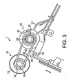
- the feeder/separator is designated generally as reference numeral 1, comprising a feeder section 10 and a separator section 20.
- the feeder comprises corrugated feed rollers 11 to 15 located on a pre-feed shaft 16.
- the separator comprises two separator rollers 21 and 22 attached to a separator shaft 23.
- the separator shaft 23 and prefeed shaft 16 are connected by two plain rubber belts 31 and 32 which form part of a reverse-feed means 30.
- the belt members 31 and 32 engage the pre-feed shaft 16 around pulleys 17 (see Figures 1 and 3 ) and 18 (see Figure 3 ), respectively and engage the separator shaft 23 around pulleys 24 and 25, respectively.
- a plurality of envelopes in a stack on the envelope platform are raised towards the feed rollers 11 to 15 in the platform feed direction P.
- the feed rollers then engage the uppermost few envelopes in the stack and feed them towards the separator rollers 21 and 22.
- a single one of the plurality of envelopes is fed into the folder/inserter apparatus in the envelope feed direction F (see Figures 1 and 3 ).
- the separator roller Of the envelopes initially fed into the separator section 20, only a single envelope is fed immediately into the folder/inserter apparatus by the separator roller, the remaining envelopes being caught by a separator pad located opposite the separator roller.
- the remaining envelopes are then subsequently fed one-at-a-time into the folder/inserter apparatus by the separator. In this way, it can be certainly assured that during an envelope feed operation of the folder/inserter apparatus, only a single envelope will be fed into the apparatus to the inserting location at any one time.
- references to feeding the envelopes "one-at-a-time" to the folder/inserter denote that the envelopes are not overlapped as they pass into the machine. However, subsequent envelopes may be fed into the folder/inserter before the first envelope has been ejected from the machine.
- Attached to the plain rubber belts 31 and 32 are two flippers 33 and 34, respectively.
- an envelope clearance process is then initiated which clears envelopes from the separator region by driving the rubber belts 31 and 32 in the reverse feed direction R ( Fig. 3 ).
- This causes the flippers 33 and 34 to engage the remaining envelopes at the inlet of the separator 20 and to return them to the stack of envelopes on the envelope carrying platform.
- operation of the reverse-feed means 30 is intended to be activated only upon a command input to the folder/inserter machine to lower the envelope feed platform.
- a command is given, for instance by depression of a relevant button, the platform is lowered and the separator shaft is caused to rotate in the reverse feed direction, returning any remaining envelopes to the stack of envelopes on the envelope-carrying platform.
- the flippers 33 and 34, as well as the belt members 31 and 32, are positioned out of the envelope feed path in order to prevent them from engaging with the incoming envelopes as they are fed towards the separator 20.
- Pulleys 17 and 18 on the pre-feed shaft 16 are free to rotate and do not apply or receive any significant torque to or from the pre-feed shaft 16.
- pulleys 24 and 25 on the separator shaft 23 are attached via one-way clutches to the shaft.
- the pulleys 24 and 25 exert little or no force on separator shaft 23, and the rubber belts 31 and 32 remain stationary, with flippers 33 and 34 held away from the envelope-feeding region by stops 26 and 27 formed as part of the separator.
- the separator mechanism is formed from a pair of separator rollers 21 and 22.
- These rollers may be formed as two independent separator rollers, or may be formed as a unitary body having a central circumferential groove therebetween.
- the rollers intermesh loosely with the separator pad 29, which is formed as a cuboid block having two grooves therein into which the separator rollers 21 and 22 are located. Envelopes being fed through the separator section 20 are then forced to adopt an undulating corrugated profile over the three peaks produced in the separator pad 29 and beneath the two separator rollers 21, 22. For this reason, such separators are known as "corrugated separators".
- corrugated separators are particularly useful for separating folded sheet material, such as envelopes, etc. as the corrugated profile gives the sheet material extra strength in the longitudinal direction as it passes through separator 20, to thereby resist unwanted folding and creasing of the sheets.
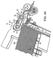
- FIG. 4A a plurality of envelopes are placed in a substantially vertical stack upon platform 50.
- Platform 50 is raised to bring the top envelope SS1 in the stack into contact with the pre-feed rollers 11 to 15 (although only rolier 13 is depicted in Figures 4A to 4D ).
- the prefeed rollers 11 to 15 are biased by their self-weight against the top of the envelope stack.
- the separator mechanism 10 is able to rotate around an axis co-axial with the axis of rotation of the separator shaft 23.
- This arcuate motion is denoted in Figures 4A to 4D by the arrow labelled ⁇ .
- the continued upward pressure caused by lifting of platform 50 forces the envelopes in the stack against pre-feed rollers 11 to 15, causing the pre-feed mechanism to rotate along the arcuate path ⁇ .
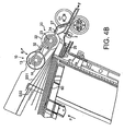
- the top few envelopes are fed by the pre-feed mechanism 10 to the separator mechanism 20.
- two envelopes SS1 and SS2 are shown being fed to the separator roller 22 by the pre-feed roller 13.
- the top few envelopes are caused to pivot about their leading edges, resulting in a fan-like expansion of the top few envelopes.
- This causes further upward motion of pre-feed system 10 about the axis of rotation of separator shaft 23 along the arcuate path ⁇ . This ensures that the pre-feed rollers 11 to 15 contact the envelopes with the desired predetermined biasing force due to their self-weight, and also that the pre-feed rollers engage the envelopes near to the envelope leading edge in order to provide a controlled drive force to the envelopes.
- the top envelope SS1 passes through the separator mechanism 20 between feed rollers 21 and 22 and separator pad 29, it is guided into the envelope feed path 2 before being fed into the folder/inserter apparatus in envelope feed direction F.
- the second envelope SS2 becomes retarded by the separator section 20, allowing only the first envelope SS1 to be fed along the feed path 2.
- the separator rollers 21,22 are braked when the first envelope SS1 has passed, by shorting-out the separator roller motor(s) so that the back EMF halts the second envelope SS2.
- Second and subsequent envelopes SS2, etc. can subsequently also be fed oneat-a-time along the path 2 from the intermediate staging position where they are engaged by the separator section 20, as shown in Figure 4D .
- envelopes continue to be fed one-at-time from the stack by the pre-feed section 10 and through the separator section 20 to the folderlinserter apparatus.
- the separator shaft rotates in the reverse feed direction R and the one-way clutches of pulleys 24 and 25 engage to rotate belts 31 and 32.
- This causes flippers 33 and 34 to disengage from stops 26 and 27 and to then return any remaining envelopes to the envelope feed platform, thereby preventing interference with the platform mechanism and reducing the potential for paper jams within the apparatus.
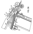
- a reverse-feed process then occurs in which feed rollers 21 and 22 are caused to rotate in the reverse direction R under a limited torque, as discussed previously herein.
- belts 31 and 32 (only belt 32 is shown in Figure 5B ) also rotate in the reverse feed direction R. This causes the flippers 33 and 34 to move away from stops 26 and 27.
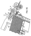
- the belt 32 has rotated to move flipper 34 away from stop 27 and into contact with envelope SS2 at the envelope lead edge.
- Belt 32 and flipper 34 then continue to rotate, as shown in Figure 5C , thereby returning envelopes SS2 and SS3, along with any others, to the stack of envelopes supported by platform 50.
- the reverse-feed of the envelopes is initially assisted by the reversefeed of the separator rollers in the reverse-feed direction R.
- the flippers 33 and 34 then return any remaining envelopes to the stack.
- the pre-feed mechanism 10 also falls, along the arcuate path ⁇ about the rotational axis of separator shaft 23. From the position shown in Figure 5C , the platform 50 is lowered further until contact between the feed-rollers 11 to 15 is broken, and further envelopes may then be added to the stack to replenish the supply of envelopes to the folder/inserter machine 1.
- the belts 31 and 32 continue to rotate in the reverse-feed direction R and flippers 33 and 34 are thereby returned to stops 26 and 27 to allow a normal feed process to resume.
- separator rollers 21 and 22 are simply attached to separator shaft 23 and allowed to rotate in the reverse-feed direction R during a reverse-feed process.
- the pre-feed rollers 11-15 can "push” the envelopes being fed faster than the separator rollers 21, 22 are feeding the envelope, or that a further feed roller located downstream of the separator 20 can "pull” the envelopes being fed faster than the separator rollers 21, 22 are feeding them Therefore, separator rollers 21 and 22 will normally be attached to separator shaft 23 by one-way clutches (not shown), to allow the separator rollers to "over-run” the separator shaft in the feeding direction R.
- a compression spring and washer are provided to apply a force against the over-run clutches associated with each of the separator rollers 21 and 22 on the separator shaft 23.
- These compression springs apply a force sufficient to cause the clutch to become engaged and to rotate in the reverse direction, but only at a limited torque below a predetermined threshold dictated by the compression spring.
- This reverse rotation of the separator rollers helps to return any envelopes to the feed platform, and particularly those trapped in the nip between the separator rollers.
- the predetermined threshold torque may be selected as appropriate for the apparatus, taking consideration of separator nip forces, materials selection, etc.
- the reverse-feed means 30 described herein comprises plain rubber belts 31 and 32 each having a single flipper 33 and 34, respectively, there is no strict requirement regarding the form and construction of these separate elements.
- the flippers 33 and 34 are shownto be moulded integrally with the rubber belts 31 and 32, they may also be formed as separate components.
- the flippers 33 and 34 could be attached to the belt members 31 and 32 in a hinged fashion at the region of the joint (shown as 35 in Figure 3 ).
- belts have been described as rubber (elastomeric) belts 31 and 32, it is envisaged that any suitable material could be used to a form a belt, or that the mechanism could be replaced with, for example, a chain-link belt or other similar device.
- the flipper need not be formed from rubber, but should have a construction which is at least partially flexible, and should have a contact surface for engaging the envelopes remaining in the feeder/separator 1 in a manner which will return the envelopes to the stack on the envelope platform through frictional contact.
- the feeder/separator mechanism is shown to have five pre-feed rollers 11 to 15 and two separator rollers 21, 22.
- the construction of the feeder/separator is not critical to the present inventive concept, such that any suitable pre-feed rollers, in any suitable number, may be used, as well as using any suitable type and number of separator rollers.
- the pre-feed rollers are shown to have tread-like teeth on the outer surface for increasing grip on the sheets being fed, but any suitable design of feed roller may be used.
- the precise construction of the separator 20 is not to be seen as limited to corrugated separators, as many alternative separators exist which may be substituted therefor.
- the embodiment disclosed herein uses rubber belts coupled to relatively inexpensive clutching devices in order to provide a reverse feed operation for envelopes.
- This represents an effective and efficient means for returning envelopes at the inlet to the feeder/separator back to the stack of envelopes on the envelope carrying platform.
- the reverse-feed mechanism be operated only when the envelope-carrying platform is lowered, it would also be possible to activate the clearance process after each individual envelope has been fed through the separator.
- the separator rollers may be driven in the reverse direction, but only at a limited torque defined by clutch bearings and a compression spring acting against the separator roller one-way clutch bearings to define a pre-determined maximum torque at which the separator rollers will rotate. This advantageously both frees envelopes from the separator roller nips and also helps to thrust them towards the lowered feed platform.
- a reverse-feed mechanism 30 is used to return envelopes remaining at the separator inlet to the stack of envelopes on the envelope feed platform. It should be noted, however, that the envelope clearance process could also simply remove the envelopes from the separator region. Clearance could equally be achieved by reversing the envelopes in a non-controlled manner, thereby simply ejecting them in the general direction of the envelope feed platform without them rejoining the ordered stack stored on the platform. Alternatively, the remaining envelopes could be cleared simply by removing them from the separator region, for example by ejecting them from the folder/inserter machine in a sideways direction to the envelope feed direction.
- Feeders of the present type utilizing such a clearance process, would find application in any sheet-feeding component of general sheet-handling devices, but particularly those having enclosed feeding locations which have hardto-access regions requiring clearance.
Landscapes
- Engineering & Computer Science (AREA)
- Mechanical Engineering (AREA)
- Sheets, Magazines, And Separation Thereof (AREA)
- Delivering By Means Of Belts And Rollers (AREA)
Claims (17)
- Blattzuführer zum Zuführen von Blättern eines pro Zeit entlang eines Weges, mit:einer Vorrichtung (50) zum Speichern einer Vielzahl von Blättern;einem Zuführer/Trenner (1) mit einer Zuführvorrichtung (10) zum Eingreifen in die Blätter und Zuführen dieser von der Vorrichtung zum Speichern und einem Trenner (20) zum Eingreifen in Blätter, die von der Zuführvorrichtung zugeführt werden, um dadurch einzelne der Blätter eines pro Zeit entlang des Weges (2) zuzuführen, während verbleibende Blätter, die nicht entlang des Pfades zugeführt werden, von dem Trenner angehalten werden; undeinem Beseitigungsmechanismus (30) zum Eingreifen in die verbleibenden Blätter und Entfernen von diesen aus dem Trennerbereich in einem Blattbeseitigungsprozess, wobei der Beseitigungsmechanismus zumindest einen Riemen (31, 32) und zumindest einen Abstandsfühler (33, 34) umfasst, der an dem zumindest einen Riemen befestigt ist, wobei der zumindest eine Abstandsfühler (33, 34) konfiguriert ist, um in die verbleibenden Blätter einzugreifen, um eine Beseitigung der Blätter aus dem Trennerbereich zu bewirken.
- Zuführer nach Anspruch 1, wobei die Vorrichtung zum Speichern einer Vielzahl von Blättern eine Plattform (50) umfasst, die beweglich zwischen einer Vollposition und einer Leerposition zum Speichern einer Vielzahl von Blättern in einem Stapel auf dieser ist.
- Zuführer nach Anspruch 2, wobei die Plattform (50) von der Vollposition zu der Leerposition in einer Plattformzuführrichtung (P) zum Treiben von Blättern in dem Stapel zu der Zuführvorrichtung (10) vorgespannt ist.
- Zuführer nach Anspruch 1, 2 oder 3, wobei die Zuführvorrichtung zumindest eine Zuführrolle (11, 12, 13, 14, 15) umfasst.
- Zuführer nach Anspruch 4, wobei jede Zuführrolle (11, 12, 13, 14, 15) eine geriffelte Rolle ist.
- Zuführer nach Anspruch 1, wobei der Beseitigungsmechanismus (30) ein Paar von Riemen (31, 32) umfasst, die jeweils an einem jeweiligen Abstandsfühler (33, 34) befestigt sind.
- Zuführer nach einem der vorangehenden Ansprüche, weiter mit einer Einwegkupplung, die in Verwendung arbeitet, wenn ein Blatt zugeführt wird, um den Beseitigungsmechanismus (30) daran zu hindern, aktiv zu werden.
- Zuführer nach Anspruch 7, wobei während dem Blattbeseitigungsprozess es die Einwegkupplung erlaubt, dass der zumindest eine Riemen (31, 32) sich dreht, um den zumindest einen Abstandsfühler (33, 34) zu veranlassen, beliebige verbleibende Blätter an den Stapel zurückzugeben.
- Zuführer nach einem der vorangehenden Ansprüche, weiter mit einem Grenzdrehmomentkupplungsmechanismus, der in Verwendung dazu dient, eine Rückbewegung des Trenners (30) zu verhindern, der jedoch vorgespannt ist, um es dem Trenner (20) zu erlauben umzukehren, wenn ein angelegtes Drehmoment unter einen Schwellpegel während dem Blattbeseitigungsprozess liegt.
- Zuführer nach Anspruch 9, wobei die Grenzdrehmomentkupplung eine Einwegkupplung und eine Vorspannvorrichtung umfasst, die gegen die Einwegkupplung agiert, um es der Einwegkupplung zu erlauben, ein begrenztes Drehmoment in der normal inaktiven Richtung anzulegen.
- Zuführer nach einem der vorangehenden Ansprüche, wobei der Trenner (20) eine Trennerrolle (21, 22) und einen Reibungsblock (29) zum Trennen einzelner Blätter von einer Vielzahl von Blättern an dem Trenner umfasst.
- Zuführer nach einem der vorangehenden Ansprüche, wobei der Beseitigungsmechanismus (30) ein Zurückgabemechanismus zum Zurückgeben von Blättern, die an dem Trenner (20) verbleiben, zu der Vorrichtung zum Speichern (50) während dem Blattbeseitigungsprozess ist.
- Zuführer nach einem der vorangehenden Ansprüche, wobei der Zuführer ein Umschlagszuführer ist und die zuzuführenden Blätter Umschläge sind.
- Verfahren eines Zuführens von Blättern eines pro Zeit zu einer Maschine, mit den Schritten:(i) Bereitstellen einer Vielzahl von Blättern in einem Stapel;(ii) Eingreifen in Blätter in dem Stapel mit einer Zuführrolle (11, 12, 13, 14, 15) und Zuführen von diesen durch einen Trenner (20) zu der Maschine;(iii)Eingreifen in Blätter, die durch den Trenner zugeführt werden mit einer Trennerrolle (21, 22), um es lediglich einem einzelnen Blatt zu erlauben, in die Maschine zugeführt zu werden und Anhalten verbleibender Blätter an dem Trenner; und(iv) Betreiben eines Zurückgabemechanismus (30), um beliebige verbleibende Blätter an den Stapel zurückzugeben, wobei der Zurückgabemechanismus zumindest einen Riemen (31, 32) umfasst, der mit einem Abstandsfühler (33, 34) verbunden ist, wobei der Abstandsfühler zum Eingreifen in verbleibende Blätter in dem Trenner und Zurückgeben von diesen an den Stapel dient.
- Verfahren nach Anspruch 14, wobei ein selektiver Betrieb des Zurückgabemechanismus von einem Kupplungsmechanismus gesteuert wird.
- Verfahren nach Anspruch 14 oder 15, wobei während einem Betrieb des Zurückgabemechanismus, die Trennerrolle (21, 22) umgekehrt rotieren darf, vorausgesetzt das Umkehrdrehmoment verbleibt unter einem Schwellpegel.
- Verfahren nach einem der Ansprüche 14, 15 oder 16, wobei die Blätter Umschläge sind.
Applications Claiming Priority (1)
| Application Number | Priority Date | Filing Date | Title |
|---|---|---|---|
| GB0420039A GB0420039D0 (en) | 2004-09-09 | 2004-09-09 | Feed of sheet material in a feeder/separator |
Publications (2)
| Publication Number | Publication Date |
|---|---|
| EP1634829A1 EP1634829A1 (de) | 2006-03-15 |
| EP1634829B1 true EP1634829B1 (de) | 2009-04-15 |
Family
ID=33186743
Family Applications (1)
| Application Number | Title | Priority Date | Filing Date |
|---|---|---|---|
| EP20050019705 Expired - Lifetime EP1634829B1 (de) | 2004-09-09 | 2005-09-09 | Vorrichtung zur Vereinzelung/Führung des Blattes |
Country Status (3)
| Country | Link |
|---|---|
| EP (1) | EP1634829B1 (de) |
| DE (1) | DE602005013867D1 (de) |
| GB (1) | GB0420039D0 (de) |
Family Cites Families (2)
| Publication number | Priority date | Publication date | Assignee | Title |
|---|---|---|---|---|
| GB2127383B (en) * | 1982-09-21 | 1986-08-13 | Xerox Corp | Sheet separator and retard mechanism |
| US6425578B1 (en) * | 1999-09-14 | 2002-07-30 | Fujifilm Electronic Imaging Limited | Image recording apparatus and method |
-
2004
- 2004-09-09 GB GB0420039A patent/GB0420039D0/en not_active Ceased
-
2005
- 2005-09-09 DE DE200560013867 patent/DE602005013867D1/de not_active Expired - Lifetime
- 2005-09-09 EP EP20050019705 patent/EP1634829B1/de not_active Expired - Lifetime
Also Published As
| Publication number | Publication date |
|---|---|
| EP1634829A1 (de) | 2006-03-15 |
| DE602005013867D1 (de) | 2009-05-28 |
| GB0420039D0 (en) | 2004-10-13 |
Similar Documents
| Publication | Publication Date | Title |
|---|---|---|
| JP5027726B2 (ja) | シート処理装置及びこれを用いた画像形成システム | |
| US6302606B1 (en) | Sheet receiving/stacking device, and image forming apparatus having the same | |
| EP0429639A1 (de) | Dokumentausgabegerät mit antizerzausvorrichtung | |
| US6824131B2 (en) | Method and apparatus for image forming and effectively performing sheet feeding using a sheet feed roller and a tilt member | |
| JPS5957841A (ja) | シ−ト送り装置 | |
| US7300049B2 (en) | Feed of sheet material in a feeder/separator | |
| US4043549A (en) | Impact feeder | |
| US5642598A (en) | Collation feeding mechanism for envelope inserting machine | |
| US5947466A (en) | Continuous belt drive paper feed system | |
| EP1634829A1 (de) | Vorrichtung zur Vereinzelung/Führung des Blattes | |
| JP5416806B2 (ja) | シート処理装置及びこれを備えた製本装置並びに画像形成システム | |
| JP2547978B2 (ja) | シート材給送装置 | |
| US20060244192A1 (en) | Processing device and image forming device | |
| CN102514970A (zh) | 薄片处理装置以及薄片处理装置的处理方法 | |
| JP3633701B2 (ja) | 給紙装置 | |
| JP7721881B2 (ja) | 後処理装置 | |
| US7621517B2 (en) | Re-circulating paper accumulator | |
| JPH0328026Y2 (de) | ||
| JP2000289873A (ja) | 給紙装置および給紙方法 | |
| JP2006256729A (ja) | シート処理装置 | |
| JPH11246064A (ja) | 記録媒体給送装置 | |
| JP3542526B2 (ja) | 給紙装置及びこれを備えた画像形成装置 | |
| JPH0246494B2 (ja) | Shokyusosochi | |
| JP2007091432A (ja) | シート処理装置及びこれを備えた画像形成装置 | |
| JP2002241030A (ja) | 用紙処理装置 |
Legal Events
| Date | Code | Title | Description |
|---|---|---|---|
| PUAI | Public reference made under article 153(3) epc to a published international application that has entered the european phase |
Free format text: ORIGINAL CODE: 0009012 |
|
| 17P | Request for examination filed |
Effective date: 20050909 |
|
| AK | Designated contracting states |
Kind code of ref document: A1 Designated state(s): AT BE BG CH CY CZ DE DK EE ES FI FR GB GR HU IE IS IT LI LT LU LV MC NL PL PT RO SE SI SK TR |
|
| AX | Request for extension of the european patent |
Extension state: AL BA HR MK YU |
|
| 17Q | First examination report despatched |
Effective date: 20060928 |
|
| AKX | Designation fees paid |
Designated state(s): DE FR GB |
|
| GRAP | Despatch of communication of intention to grant a patent |
Free format text: ORIGINAL CODE: EPIDOSNIGR1 |
|
| GRAS | Grant fee paid |
Free format text: ORIGINAL CODE: EPIDOSNIGR3 |
|
| GRAA | (expected) grant |
Free format text: ORIGINAL CODE: 0009210 |
|
| AK | Designated contracting states |
Kind code of ref document: B1 Designated state(s): DE FR GB |
|
| REG | Reference to a national code |
Ref country code: GB Ref legal event code: FG4D |
|
| REF | Corresponds to: |
Ref document number: 602005013867 Country of ref document: DE Date of ref document: 20090528 Kind code of ref document: P |
|
| PLBE | No opposition filed within time limit |
Free format text: ORIGINAL CODE: 0009261 |
|
| STAA | Information on the status of an ep patent application or granted ep patent |
Free format text: STATUS: NO OPPOSITION FILED WITHIN TIME LIMIT |
|
| 26N | No opposition filed |
Effective date: 20100118 |
|
| PGFP | Annual fee paid to national office [announced via postgrant information from national office to epo] |
Ref country code: FR Payment date: 20111005 Year of fee payment: 7 |
|
| REG | Reference to a national code |
Ref country code: FR Ref legal event code: ST Effective date: 20130531 |
|
| PG25 | Lapsed in a contracting state [announced via postgrant information from national office to epo] |
Ref country code: FR Free format text: LAPSE BECAUSE OF NON-PAYMENT OF DUE FEES Effective date: 20121001 |
|
| PGFP | Annual fee paid to national office [announced via postgrant information from national office to epo] |
Ref country code: DE Payment date: 20180927 Year of fee payment: 14 |
|
| PGFP | Annual fee paid to national office [announced via postgrant information from national office to epo] |
Ref country code: GB Payment date: 20180927 Year of fee payment: 14 |
|
| REG | Reference to a national code |
Ref country code: DE Ref legal event code: R119 Ref document number: 602005013867 Country of ref document: DE |
|
| PG25 | Lapsed in a contracting state [announced via postgrant information from national office to epo] |
Ref country code: DE Free format text: LAPSE BECAUSE OF NON-PAYMENT OF DUE FEES Effective date: 20200401 |
|
| GBPC | Gb: european patent ceased through non-payment of renewal fee |
Effective date: 20190909 |
|
| PG25 | Lapsed in a contracting state [announced via postgrant information from national office to epo] |
Ref country code: GB Free format text: LAPSE BECAUSE OF NON-PAYMENT OF DUE FEES Effective date: 20190909 |