EP1635050A2 - Dispositif de fixation pour un échangeur de chaleur d'air de suralimentation dans un véhicule automobile - Google Patents
Dispositif de fixation pour un échangeur de chaleur d'air de suralimentation dans un véhicule automobile Download PDFInfo
- Publication number
- EP1635050A2 EP1635050A2 EP05016392A EP05016392A EP1635050A2 EP 1635050 A2 EP1635050 A2 EP 1635050A2 EP 05016392 A EP05016392 A EP 05016392A EP 05016392 A EP05016392 A EP 05016392A EP 1635050 A2 EP1635050 A2 EP 1635050A2
- Authority
- EP
- European Patent Office
- Prior art keywords
- charge air
- fastening arrangement
- arrangement according
- nozzle body
- boxes
- Prior art date
- Legal status (The legal status is an assumption and is not a legal conclusion. Google has not performed a legal analysis and makes no representation as to the accuracy of the status listed.)
- Withdrawn
Links
Images

Classifications
-
- F—MECHANICAL ENGINEERING; LIGHTING; HEATING; WEAPONS; BLASTING
- F02—COMBUSTION ENGINES; HOT-GAS OR COMBUSTION-PRODUCT ENGINE PLANTS
- F02B—INTERNAL-COMBUSTION PISTON ENGINES; COMBUSTION ENGINES IN GENERAL
- F02B29/00—Engines characterised by provision for charging or scavenging not provided for in groups F02B25/00, F02B27/00 or F02B33/00 - F02B39/00; Details thereof
- F02B29/04—Cooling of air intake supply
- F02B29/045—Constructional details of the heat exchangers, e.g. pipes, plates, ribs, insulation, materials, or manufacturing and assembly
-
- Y—GENERAL TAGGING OF NEW TECHNOLOGICAL DEVELOPMENTS; GENERAL TAGGING OF CROSS-SECTIONAL TECHNOLOGIES SPANNING OVER SEVERAL SECTIONS OF THE IPC; TECHNICAL SUBJECTS COVERED BY FORMER USPC CROSS-REFERENCE ART COLLECTIONS [XRACs] AND DIGESTS
- Y02—TECHNOLOGIES OR APPLICATIONS FOR MITIGATION OR ADAPTATION AGAINST CLIMATE CHANGE
- Y02T—CLIMATE CHANGE MITIGATION TECHNOLOGIES RELATED TO TRANSPORTATION
- Y02T10/00—Road transport of goods or passengers
- Y02T10/10—Internal combustion engine [ICE] based vehicles
- Y02T10/12—Improving ICE efficiencies
Definitions
- the invention relates to a mounting arrangement for a charge air cooler in a motor vehicle, the charge air cooler having air boxes with charge air pipe for the inlet and outlet of charge air.
- the interface is designed as a flexible flow channel element, preferably as an elastic hose through which the charge air flows, but which does not transmit any moments from the charge air nozzle to the charge air box.
- tension struts are added to the charge air stub or the stub body, which absorb the gas forces acting on the charge air stacks and initiate directly into the frame of the vehicle - in principle this can also be done by only one, preferably symmetrically arranged, tension strut.
- the attachment point for the articulation of the tie rods is arranged on the charge air nozzle or the nozzle body that it is "torque-free" - ie the sum of the resulting from the gas forces and the Switzerlandstreben feature moments is approximately equal to zero in the attachment point ,
- the gas forces act on the one hand on the inlet and outlet cross-section of the charge air nozzle and on the other hand on the interface cross-section.
- the intercooler is connected to a coolant radiator to a cooling module, which is supported on the vehicle side via the coolant radiator.
- the charge air nozzles are connected in the region of the attachment point for the tie rods with the coolant radiator, so that the tie rods support the coolant cooler and thus the cooling module on the vehicle side in addition to the introduction of the gas forces in the vehicle frame. This is particularly advantageous when the coolant radiator is mounted in a further advantageous embodiment of the invention via lateral support or pivot bearing relative to the vehicle frame. A pitching movement about the common pivot axis of the pivot bearing is then absorbed by the tie rods.
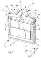
- Fig. 1 shows a perspective view of a cooling module 1, which is composed of a coolant radiator 2 and a charge air cooler 3 and a capacitor 4.
- a cooling module 1 is preferably used in commercial vehicles application, wherein the coolant radiator is connected to a coolant circuit of an internal combustion engine of the vehicle, not shown, while the intercooler is used to cool the charged combustion air of the internal combustion engine.
- the condenser 4 is connected to a not shown refrigerant circuit of an air conditioner.
- the entire cooling module 1 is over the coolant radiator - which is not shown - supported against the vehicle. All three heat exchangers 2, 3, 4 are successively flowed through by ambient air, which is conveyed by a fan, not shown.
- the intercooler 3 has - as known per se - a brazed pipe fin block 5, which from flat tubes, not shown, which can be traversed by charge air, and corrugated fins, not shown, which are covered by the cooling air, is composed.
- the ends of the tubes of the block 5 are received in tube plates 6, 7, which in turn are called with charge air boxes 8, 9, called short air boxes.
- the tube sheets 6, 7 are preferably made of an aluminum alloy and are soldered to the tube ends of the block 5.
- the air boxes 8, 9 are preferably made of plastic and connected to the tube sheets 6, 7 by a mechanical crimping connection, not shown. However, it is also possible aluminum air boxes, which are welded to the tube sheets.
- the air boxes 8, 9 each have narrow sides 8a, 9a, which are in each case in communication with hose sections 10, 11, to which each curved charge air nozzle parts 12, 13, short nozzle parts, connect.
- the nozzle parts 12, 13 are repeatedly curved - for a more detailed description, reference is made to the coordinate system 1 shown with the axes x, y, z, where x represents the direction of travel of the motor vehicle and z represents the vertical axis.
- the nozzle parts 12, 13 each have mutually tapered nozzle sections 12a, 13a and extending in the x direction inlet and outlet nozzle 12b, 13b.
- the nozzle parts 12, 13 are in the region of the inlet and outlet nozzle 12b, 13b connected by a bridge 12/13, so that they form a continuous nozzle body 14.
- the forces acting on the nozzle sections 12a and 13a do not cause any external moment about the x-axis on the nozzle body 14.
- the compressed and heated charge air enters the inlet port 12b and leaves the intercooler cooled via the outlet port 13b.
- gas forces represented by oppositely directed arrows F G in the positive and negative x direction effective.
- the tension struts 15, 16 extend substantially in the x-direction, ie, substantially parallel to the gas forces F G and direct the gas forces directly into the vehicle frame, not shown. Due to the flexibly formed tube sections 10, 11, the nozzle parts 12, 13 and the associated air boxes 8, 9 decoupled in terms of power in the x and y directions. Thus, essentially only the own weight and acceleration forces as well as gas forces in the z-direction act on the charge air cooler 3 isolated by the hose sections 10, 11. The charge air cooler 3 is connected via its air boxes 8, 9 in a manner not further explained with the frame of the coolant radiator 2. At the nozzle parts 13, 12 attachment points A, B are provided, which will be discussed in more detail below.
- Fig. 2 shows a schematic representation of the cooling module 1 (same notessziffem for the same parts are used), consisting of coolant radiator 2 and intercooler 3, which are held together by connecting elements 19, 20.
- the cooling module 1 is shown in a side view, so you can see the air box 9, which continues on its narrow side 9a in an extension piece 9b.
- the angle formed in the side view neck portion 13 (part of the nozzle body 14) has the horizontally, ie arranged in the x-direction inlet nozzle 13b and perpendicular to a nozzle section 13c, which is connected to the hose section 11, which in turn on the extension piece 9b of the air box. 9 is attached.
- the neck portion 13 is thus in fluid communication with the air box 9 via the hose portion 11, but is decoupled with respect to transmittable mechanical forces and moments.
- the hose section 11 thus forms a soft interface that transmits only gas forces.
- the neck part 13 has an attachment point A, which corresponds to the attachment points A and B in Fig. 1.
- the nipple body 14 is pivotally or fixedly connected to the radiator 2 at point A (and also at point B).
- the articulation of the tension strut (compare tension struts 15, 16 in Fig. 1) is ideally realized at the height of the attachment point A.
- the nozzle body 14 thus remains free of external moments about the y-axis.
- the entire cooling module is supported in a vehicle-side bearing 21, which has a hinge point C, through which a perpendicular to the plane, ie extending in the y-direction pivot axis.
- the cooling module 1 is thus pivotable about this pivot axis through the hinge point C - the hinged at the level of the attachment point
- a tension strut, represented by the force arrow F z catches this pitching motion of the cooling module 1 from.
- the neck part 13 is articulated in the attachment point A, wherein on each of the two flow cross-sections, a gas force, represented by each an arrow F G. with a corresponding one; not shown lever arm to the point A acts. This results in opposing moments with respect to the point A.
- the size of the gas forces F G in the x and z direction (product of cross-sectional area of the nozzle and pressure of the charge air) with the relevant lever arms is tuned in that the resultant moment about the y-axis is zero.
- the nozzle part 13 is due to the arrangement of the mounting and pivot point A free of gas forces resulting moments about an axis extending in the y-direction in front of the nozzle part 13 axis.
- no moments can be transferred to the charge air cooler 3.
- Analogous forces and moments act on the neck part 12, which forms the neck body 14 with the neck part 13.
- the invention has been described with reference to a mounting arrangement for a charge air cooler in a motor vehicle. It should be noted, however, that the mounting arrangement can also be used for other purposes.
- a Befestigunsan Aunt invention is also used in other heat exchangers, such as coolant radiator, radiator, oil cooler, condensers and / or evaporator.
Landscapes
- Engineering & Computer Science (AREA)
- Physics & Mathematics (AREA)
- Thermal Sciences (AREA)
- Chemical & Material Sciences (AREA)
- Combustion & Propulsion (AREA)
- Mechanical Engineering (AREA)
- General Engineering & Computer Science (AREA)
- Cooling, Air Intake And Gas Exhaust, And Fuel Tank Arrangements In Propulsion Units (AREA)
Applications Claiming Priority (1)
| Application Number | Priority Date | Filing Date | Title |
|---|---|---|---|
| DE102004044856.6A DE102004044856B4 (de) | 2004-09-14 | 2004-09-14 | Befestigungsanordnung für einen Ladeluftkühler in einem Kraftfahrzeug |
Publications (1)
| Publication Number | Publication Date |
|---|---|
| EP1635050A2 true EP1635050A2 (fr) | 2006-03-15 |
Family
ID=34978999
Family Applications (1)
| Application Number | Title | Priority Date | Filing Date |
|---|---|---|---|
| EP05016392A Withdrawn EP1635050A2 (fr) | 2004-09-14 | 2005-07-28 | Dispositif de fixation pour un échangeur de chaleur d'air de suralimentation dans un véhicule automobile |
Country Status (2)
| Country | Link |
|---|---|
| EP (1) | EP1635050A2 (fr) |
| DE (1) | DE102004044856B4 (fr) |
Cited By (1)
| Publication number | Priority date | Publication date | Assignee | Title |
|---|---|---|---|---|
| DE102020114756A1 (de) | 2020-06-03 | 2021-12-09 | Man Truck & Bus Se | Vorbaustruktur für ein Nutzfahrzeug, vorzugsweise für einen Lastkraftwagen |
Families Citing this family (1)
| Publication number | Priority date | Publication date | Assignee | Title |
|---|---|---|---|---|
| DE102018211151A1 (de) * | 2018-07-06 | 2020-01-09 | Bayerische Motoren Werke Aktiengesellschaft | Lager für ein Kühlmodul |
Family Cites Families (3)
| Publication number | Priority date | Publication date | Assignee | Title |
|---|---|---|---|---|
| JPS6248923A (ja) * | 1985-08-28 | 1987-03-03 | Hino Motors Ltd | タ−ボ過給エンジン |
| DE19909672B4 (de) * | 1999-03-05 | 2005-06-02 | Behr Gmbh & Co. Kg | Kühlmodul |
| DE102004044872A1 (de) * | 2004-09-14 | 2006-03-16 | Behr Gmbh & Co. Kg | Befestigungsanordnung für einen Ladeluftkühler, insbesondere ein Kühlmodul |
-
2004
- 2004-09-14 DE DE102004044856.6A patent/DE102004044856B4/de not_active Expired - Fee Related
-
2005
- 2005-07-28 EP EP05016392A patent/EP1635050A2/fr not_active Withdrawn
Cited By (3)
| Publication number | Priority date | Publication date | Assignee | Title |
|---|---|---|---|---|
| DE102020114756A1 (de) | 2020-06-03 | 2021-12-09 | Man Truck & Bus Se | Vorbaustruktur für ein Nutzfahrzeug, vorzugsweise für einen Lastkraftwagen |
| CN115697744A (zh) * | 2020-06-03 | 2023-02-03 | 曼卡车和巴士欧洲股份公司 | 用于商用车辆、优选用于载重汽车的前端结构 |
| US12377917B2 (en) | 2020-06-03 | 2025-08-05 | Man Truck & Bus Se | Front structure for a utility vehicle, preferably for a lorry |
Also Published As
| Publication number | Publication date |
|---|---|
| DE102004044856A1 (de) | 2006-03-16 |
| DE102004044856B4 (de) | 2017-10-05 |
Similar Documents
| Publication | Publication Date | Title |
|---|---|---|
| EP2044304B1 (fr) | Échangeur de chaleur avec raccord d'accouplement, par exemple refroidisseur d'air de charge, et raccord d'accouplement pour échangeur de chaleur | |
| EP1707911B1 (fr) | Échangeur de chaleur, par exemple refroidisseur d'air de suralimentation et procédé de fabrication | |
| DE60031932T2 (de) | Mehrfachwärmetauscher mit zwei Kernen | |
| DE102019128941B4 (de) | Front-Stoßfänger mit integriertem Wärmetauscher | |
| EP1118830B1 (fr) | Dispositif pour lier deux échangeurs de chaleur | |
| EP1279805A2 (fr) | Refroidisseur de l'air de charge aéroréfrigérée | |
| DE112011103814T5 (de) | Wärmetauscheranordnung und Verfahren | |
| DE102013205267A1 (de) | Luft-Flüssigkeits-Wärmetauscher | |
| DE102012202234A1 (de) | Wärmeübertrageranordnung | |
| DE112008000781T5 (de) | Wärmetauscheraufbau | |
| DE10344219A1 (de) | Wärmeübertragermodul für ein Kraftfahrzeug | |
| DE3841536A1 (de) | Anordnung eines waermetauschers | |
| DE102004044856B4 (de) | Befestigungsanordnung für einen Ladeluftkühler in einem Kraftfahrzeug | |
| DE19909672A1 (de) | Kühlmodul | |
| EP1703242B1 (fr) | Echangeur de chaleur, en particulier radiateur de liquide de refroidissement | |
| EP1845242A2 (fr) | Échangeur de chaleur pour refroidissement d'air d'admission pour véhicule et système | |
| DE102005040607A1 (de) | Anordnung zur Befestigung eines Wärmeübertragers an einem anderen | |
| DE4100483C2 (de) | Kraftfahrzeugfront mit einem durch Karosserierahmenteile umgrenzten Karosseriedurchbruch für die Anordnung eines Wärmetauschers | |
| DE102004044872A1 (de) | Befestigungsanordnung für einen Ladeluftkühler, insbesondere ein Kühlmodul | |
| DE102018130158A1 (de) | Aufdach-Klimatisierungseinheit | |
| WO2024017733A1 (fr) | Véhicule automobile équipé d'un dispositif de régulation de température | |
| DE102018001130A1 (de) | Anpassbare Luftleitanordnung | |
| DE10220544B4 (de) | Befestigungselement für einen Wärmeübertrager | |
| EP1853867A1 (fr) | Element caloporteur, notamment pour une unite de transmission thermique, et unite de transmission thermique | |
| DE102019200468A1 (de) | Kühlvorrichtung und Kraftfahrzeug |
Legal Events
| Date | Code | Title | Description |
|---|---|---|---|
| PUAI | Public reference made under article 153(3) epc to a published international application that has entered the european phase |
Free format text: ORIGINAL CODE: 0009012 |
|
| AK | Designated contracting states |
Kind code of ref document: A2 Designated state(s): AT BE BG CH CY CZ DE DK EE ES FI FR GB GR HU IE IS IT LI LT LU LV MC NL PL PT RO SE SI SK TR |
|
| AX | Request for extension of the european patent |
Extension state: AL BA HR MK YU |
|
| STAA | Information on the status of an ep patent application or granted ep patent |
Free format text: STATUS: THE APPLICATION IS DEEMED TO BE WITHDRAWN |
|
| 18D | Application deemed to be withdrawn |
Effective date: 20100130 |