EP1845242A2 - Échangeur de chaleur pour refroidissement d'air d'admission pour véhicule et système - Google Patents
Échangeur de chaleur pour refroidissement d'air d'admission pour véhicule et système Download PDFInfo
- Publication number
- EP1845242A2 EP1845242A2 EP07007157A EP07007157A EP1845242A2 EP 1845242 A2 EP1845242 A2 EP 1845242A2 EP 07007157 A EP07007157 A EP 07007157A EP 07007157 A EP07007157 A EP 07007157A EP 1845242 A2 EP1845242 A2 EP 1845242A2
- Authority
- EP
- European Patent Office
- Prior art keywords
- heat exchanger
- charge air
- stiffening
- side part
- llk1
- Prior art date
- Legal status (The legal status is an assumption and is not a legal conclusion. Google has not performed a legal analysis and makes no representation as to the accuracy of the status listed.)
- Withdrawn
Links
Images



Classifications
-
- F—MECHANICAL ENGINEERING; LIGHTING; HEATING; WEAPONS; BLASTING
- F02—COMBUSTION ENGINES; HOT-GAS OR COMBUSTION-PRODUCT ENGINE PLANTS
- F02B—INTERNAL-COMBUSTION PISTON ENGINES; COMBUSTION ENGINES IN GENERAL
- F02B29/00—Engines characterised by provision for charging or scavenging not provided for in groups F02B25/00, F02B27/00 or F02B33/00 - F02B39/00; Details thereof
- F02B29/04—Cooling of air intake supply
- F02B29/045—Constructional details of the heat exchangers, e.g. pipes, plates, ribs, insulation, materials, or manufacturing and assembly
- F02B29/0475—Constructional details of the heat exchangers, e.g. pipes, plates, ribs, insulation, materials, or manufacturing and assembly the intake air cooler being combined with another device, e.g. heater, valve, compressor, filter or EGR cooler, or being assembled on a special engine location
-
- F—MECHANICAL ENGINEERING; LIGHTING; HEATING; WEAPONS; BLASTING
- F02—COMBUSTION ENGINES; HOT-GAS OR COMBUSTION-PRODUCT ENGINE PLANTS
- F02B—INTERNAL-COMBUSTION PISTON ENGINES; COMBUSTION ENGINES IN GENERAL
- F02B29/00—Engines characterised by provision for charging or scavenging not provided for in groups F02B25/00, F02B27/00 or F02B33/00 - F02B39/00; Details thereof
- F02B29/04—Cooling of air intake supply
- F02B29/045—Constructional details of the heat exchangers, e.g. pipes, plates, ribs, insulation, materials, or manufacturing and assembly
- F02B29/0456—Air cooled heat exchangers
-
- F—MECHANICAL ENGINEERING; LIGHTING; HEATING; WEAPONS; BLASTING
- F02—COMBUSTION ENGINES; HOT-GAS OR COMBUSTION-PRODUCT ENGINE PLANTS
- F02B—INTERNAL-COMBUSTION PISTON ENGINES; COMBUSTION ENGINES IN GENERAL
- F02B29/00—Engines characterised by provision for charging or scavenging not provided for in groups F02B25/00, F02B27/00 or F02B33/00 - F02B39/00; Details thereof
- F02B29/04—Cooling of air intake supply
- F02B29/0406—Layout of the intake air cooling or coolant circuit
- F02B29/0412—Multiple heat exchangers arranged in parallel or in series
-
- F—MECHANICAL ENGINEERING; LIGHTING; HEATING; WEAPONS; BLASTING
- F02—COMBUSTION ENGINES; HOT-GAS OR COMBUSTION-PRODUCT ENGINE PLANTS
- F02M—SUPPLYING COMBUSTION ENGINES IN GENERAL WITH COMBUSTIBLE MIXTURES OR CONSTITUENTS THEREOF
- F02M26/00—Engine-pertinent apparatus for adding exhaust gases to combustion-air, main fuel or fuel-air mixture, e.g. by exhaust gas recirculation [EGR] systems
- F02M26/02—EGR systems specially adapted for supercharged engines
- F02M26/04—EGR systems specially adapted for supercharged engines with a single turbocharger
- F02M26/05—High pressure loops, i.e. wherein recirculated exhaust gas is taken out from the exhaust system upstream of the turbine and reintroduced into the intake system downstream of the compressor
-
- F—MECHANICAL ENGINEERING; LIGHTING; HEATING; WEAPONS; BLASTING
- F02—COMBUSTION ENGINES; HOT-GAS OR COMBUSTION-PRODUCT ENGINE PLANTS
- F02M—SUPPLYING COMBUSTION ENGINES IN GENERAL WITH COMBUSTIBLE MIXTURES OR CONSTITUENTS THEREOF
- F02M26/00—Engine-pertinent apparatus for adding exhaust gases to combustion-air, main fuel or fuel-air mixture, e.g. by exhaust gas recirculation [EGR] systems
- F02M26/02—EGR systems specially adapted for supercharged engines
- F02M26/04—EGR systems specially adapted for supercharged engines with a single turbocharger
- F02M26/06—Low pressure loops, i.e. wherein recirculated exhaust gas is taken out from the exhaust downstream of the turbocharger turbine and reintroduced into the intake system upstream of the compressor
-
- F—MECHANICAL ENGINEERING; LIGHTING; HEATING; WEAPONS; BLASTING
- F02—COMBUSTION ENGINES; HOT-GAS OR COMBUSTION-PRODUCT ENGINE PLANTS
- F02M—SUPPLYING COMBUSTION ENGINES IN GENERAL WITH COMBUSTIBLE MIXTURES OR CONSTITUENTS THEREOF
- F02M26/00—Engine-pertinent apparatus for adding exhaust gases to combustion-air, main fuel or fuel-air mixture, e.g. by exhaust gas recirculation [EGR] systems
- F02M26/02—EGR systems specially adapted for supercharged engines
- F02M26/08—EGR systems specially adapted for supercharged engines for engines having two or more intake charge compressors or exhaust gas turbines, e.g. a turbocharger combined with an additional compressor
-
- F—MECHANICAL ENGINEERING; LIGHTING; HEATING; WEAPONS; BLASTING
- F02—COMBUSTION ENGINES; HOT-GAS OR COMBUSTION-PRODUCT ENGINE PLANTS
- F02M—SUPPLYING COMBUSTION ENGINES IN GENERAL WITH COMBUSTIBLE MIXTURES OR CONSTITUENTS THEREOF
- F02M26/00—Engine-pertinent apparatus for adding exhaust gases to combustion-air, main fuel or fuel-air mixture, e.g. by exhaust gas recirculation [EGR] systems
- F02M26/13—Arrangement or layout of EGR passages, e.g. in relation to specific engine parts or for incorporation of accessories
- F02M26/22—Arrangement or layout of EGR passages, e.g. in relation to specific engine parts or for incorporation of accessories with coolers in the recirculation passage
- F02M26/23—Layout, e.g. schematics
-
- Y—GENERAL TAGGING OF NEW TECHNOLOGICAL DEVELOPMENTS; GENERAL TAGGING OF CROSS-SECTIONAL TECHNOLOGIES SPANNING OVER SEVERAL SECTIONS OF THE IPC; TECHNICAL SUBJECTS COVERED BY FORMER USPC CROSS-REFERENCE ART COLLECTIONS [XRACs] AND DIGESTS
- Y02—TECHNOLOGIES OR APPLICATIONS FOR MITIGATION OR ADAPTATION AGAINST CLIMATE CHANGE
- Y02T—CLIMATE CHANGE MITIGATION TECHNOLOGIES RELATED TO TRANSPORTATION
- Y02T10/00—Road transport of goods or passengers
- Y02T10/10—Internal combustion engine [ICE] based vehicles
- Y02T10/12—Improving ICE efficiencies
Definitions
- the present invention relates to a heat exchanger for charge air cooling for motor vehicles according to claim 1 and a system.
- Heat exchangers in particular for charge air cooling, usually have a finned tube block, in particular of flat tubes, and corrugated fins arranged substantially adjacent to the flat tubes.
- the tubes in particular the flat tubes, are usually inserted in tubesheets and connected to them materially, in particular by soldering, welding, gluing, etc.
- At the tube sheets mostly air collection boxes are arranged.
- Side on the finned tube block are usually side parts, in particular for stiffening of the heat exchanger, in particular the charge air cooler, arranged.
- the applicant is a heat exchanger with tubes and possibly corrugated fins and at least one known lateral side between two headers side part, wherein the side part receives at least a portion of the tensile stresses acting as a result of different thermal expansion of the tubes and corrugated ribs during operation at least on the outer tube, wherein the side part has slots and / or openings, which the spring constant the side part relative to a side part without slots and / or openings changed such that at a different longitudinal extent of the middle tubes compared to the outermost, adjacent to the side part disposed tube, which acts on the outermost tube tensile stress is reduced.
- the fact that the tensile stresses are deliberately reduced during operation, the solder joint between the outermost tube and the tube sheets is protected from overload, whereby cracks and therefore leakage of the heat exchanger can be avoided.
- a heat exchanger for intercooler for motor vehicles which has at least one tube for flow with at least one medium to be cooled, which has at least one tube plate for receiving tubes and at least one side part for stiffening the heat exchanger, wherein the heat exchanger at least one stiffening element to reduce the stresses between the tube sheet and tubes and the at least one stiffening element is integrally formed with the side part.
- the heat exchanger is in particular a charge air cooler for motor vehicles. Furthermore, however, the heat exchanger can also be a coolant cooler and / or an oil cooler and / or an exhaust gas cooler and / or a condenser for an air conditioning system and / or a gas cooler for an air conditioning system and / or an evaporator for an air conditioning system.
- At least one tube, in particular a number of tubes, in particular flat tubes, for the flow through with at least one medium to be cooled, in particular charge air are at least in a tube plate, in particular in two tube plates, added.
- At least one side part, in particular two side parts serve to stiffen the heat exchanger, in particular the intercooler.
- At least one stiffening element serves to reduce the stresses between tube sheet, in particular between the two tube sheets and, the at least one tube, in particular the tubes, in particular the flat tubes.
- the at least one stiffening element is formed integrally with the at least one side part.
- the at least one stiffening element is formed at least in sections as an angle element.
- the at least one angle element, in particular the angle elements can particularly advantageously stiffen the heat exchanger, in particular the intercooler, so that the stresses between tube plate, in particular the tube plates and, the at least one tube, in particular the tubes, are particularly advantageously reduced.
- the at least one stiffening element has at least one stiffening element opening for the flow through of the stiffening element with cooling medium.
- the at least one stiffening element is formed integrally with the side part.
- the at least one side part and the at least one stiffening element are integrally formed.
- at least one step can be saved particularly advantageous.
- additional installation work accounts for particularly advantageous.
- at least one side part can be formed integrally with two, three, four or more than four stiffening elements.
- the at least one stiffening element has at least one recess for Umformverêtung.
- the stiffening element can be reshaped particularly advantageous, in particular bent or folded.
- the heat exchanger has at least four stiffening elements.
- the heat exchanger, in particular the intercooler are stiffened particularly advantageous.
- the heat exchanger on ribs in particular corrugated fins to increase the heat transfer.
- the heat transfer can be improved particularly advantageous.
- the heat exchanger has at least one tube bundle of tubes for flowing through with charge air. In this way, the heat transfer performance can be increased particularly advantageous. Furthermore, the assembly can be carried out very easily.
- a further advantageous embodiment is characterized in that the heat exchanger has at least one collecting box, in particular at least two collecting boxes, for charge air collection and / or charge air diffusion.
- the charge air can be particularly advantageous to the individual tubes, in particular flat tubes, divided or collected particularly advantageous after flowing through the heat exchanger, in particular the charge air cooler.
- the heat exchanger is a cooling module.
- space can be saved particularly advantageously by a substantially adjacent arrangement of at least one coolant cooler and / or at least one charge air cooler and / or at least one condenser for an air conditioning system and / or at least one oil cooler and / or at least one exhaust gas cooler.
- a system with at least one heat exchanger according to one of claims 1 to 9 which has at least one internal combustion engine for a motor vehicle, at least one first turbine of an exhaust gas turbocharger and at least one second heat exchanger for coolant cooling.
- the at least one first turbine can drive a compressor for charge air compression.
- coolant in particular water-containing cooling fluid, in particular water-containing cooling fluid, can cool the engine in the at least one second heat exchanger for coolant cooling.
- the system has at least one third heat exchanger for exhaust gas cooling and / or at least one condenser for an air conditioning system.
- recirculated exhaust gas can be cooled particularly advantageously in the at least one third heat exchanger and the charge air can then be supplied again.
- at least one refrigerant of an air conditioning system can be cooled particularly advantageously in at least one condenser for an air conditioning system.
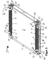
- FIG. 1 shows an isometric representation of a heat exchanger 1 for intercooling with two side parts 8, each with four stiffening angles 9.
- the heat exchanger 1 in particular the charge air cooler, has a finned tube block 2 with a number of flat tubes 3 and a number of corrugated fins 4.
- the flat tubes 13 are arranged substantially parallel to each other. Between adjacent flat tubes always a corrugated fin 4 is arranged.
- the flat tubes 3 are each inserted into two tube plates 7 in unspecified tube bottom openings.
- the flat tubes 3 are formed of a metal, in particular aluminum, in particular solder-plated aluminum.
- the corrugated fins 4 are also made of a metal, in particular aluminum. In the illustrated embodiment, the corrugated fins 4 are solder plated. In a Lotplatttechnik solder is rolled onto the appropriate metal.
- the flat tubes 3 are inserted into the two tubesheets 7 and positively connected, for example by reshaping or crimping, and / or materially connected by soldering, welding, gluing, etc. with the tube plates 7.
- the tube plate 7 is formed of a metal, in particular aluminum or stainless steel.
- the flat tubes 3 and / or the corrugated fins 4 may be formed of stainless steel.
- an air box 5 is cohesively, for example, by soldering, welding, gluing, etc., and / or positively connected by crimping, folding or crimping with the tube sheet 7.
- the air box is formed in the illustrated embodiment of a metal, such as aluminum, in particular solder-plated aluminum, or of another metal such as stainless steel.
- the air box 5 is made of plastic or of a fiber composite material.
- the air box 5 has an air inlet and / or air outlet nozzle for the inlet and / or outlet of charge air.
- the air inlet and / or outlet nozzle 6 grows, is arcuately in an elongated distribution or collection section of the air box 5 via.
- the air inlet and / or air outlet nozzle 6 is substantially straight or at an angle of 0 ° to 90 ° in the elongated unspecified air distribution or air collecting section over.
- the air inlet and / or air outlet nozzle 6 is formed in one piece with the air box 5 in the illustrated embodiment.
- the side part 8 is substantially made of a metal such as aluminum or stainless steel or of any other steel or of a fiber composite material substantially laterally on the two unspecified sides of the heat exchanger 1 substantially parallel to the flat tubes 3 educated.
- the side part essentially has an unspecified sheet-like, essentially rectangular middle section.
- Side panel slots 14 are incorporated in the center section. The side part slots essentially serve to adapt the spring constants of the side part 8 in the respective operating states of the heat exchanger, in particular the intercooler.
- a part of the side part material of the side part 8 is deformed, for example by bending, that the side part 8 adjacent corrugated fin 4 is deformed in the region of the 9.teilaussparung 12 by the material of the second part that they are not from the specified space between
- a tab is arranged in such a way and formed from the side part 8, that an unspecified designated side part and the adjacent to the side part 8 arranged flat tube Tongue of the tube sheet 7 can be inserted through the unspecified tab of the side part 8, so that the side part 8 and the tubesheet 7 are positively connected, for example by bending or bending, or at least fixed together.
- stiffening angles 9 are respectively formed at the ends of the side part. At one end are two stiffening angles 9 arranged.
- the side part 8 a total of four stiffening angle 9, two at each of two end portions of the side part 8.
- the stiffening angle 9 are arranged substantially perpendicular to the unspecified extension direction of the flat tubes 3.
- the stiffening angles are arranged such that the air flow direction LR forms the normal vector of the unspecified stiffening angle surface of the stiffening angle 9.
- the stiffening angle 9 have in the illustrated embodiment substantially a triangular shape.
- the stiffening angles can have, at least in sections, a round and / or corrugated and / or polygonal and / or elliptical shape and / or a combination of the abovementioned shapes.
- two stiffening angles 9 essentially surround the finned tube block 2, at least in sections.
- all four stiffening angles 9 have at least one stiffening angle opening 13.
- Stiffening angle opening 13 is formed substantially window-like, so that air for cooling the charge air through the stiffening angle through unspecified openings can flow into the corrugated fins, so that the air flow of the cooling air is only slightly impeded.
- the stiffening angle 9 has two, three, four or more than four stiffening angle openings 13.
- the stiffening angle openings 13 may be formed, for example, as bores, as triangular or quadrangular or polygonal openings or as oval slots or as a combination of the aforementioned forms.
- the stiffening angle 9 touch the tube sheet 7 at least in sections in the connecting region 15.
- the stiffening angle 9 at least partially cohesively with flat tubes 3 and / or corrugated fins 4, for example, by soldering, welding, gluing, etc.
- the stiffening angle 9, material fit, for example by soldering, gluing, welding, and / or positively connected, for example by folding, crimping, crimping, etc. in the connection region 15 with the tube sheets 7 and / or connected to at least one tubesheet 7.
- a first fastener 10 serves for fastening the heat exchanger 1, in particular the charge air cooler, for example for attachment to a coolant radiator, for example a cooling module or for attachment to a vehicle body or combustion engine section.
- the first fastening element 10 is formed integrally with the air box 5.
- the first fastening element 10 is positively and / or materially connected to the air box 5, for example by soldering, welding, gluing, etc. with the air box 5.
- a second fastening element 11 is arranged on the air box 5.
- the fastener 10 is integrally formed with the air box 5.
- the second fastening element 11 with the air box 5 is materially connected, for example, by soldering, welding, gluing, etc. with the air box 5.
- the second fastening element 11 also serves to attach another heat exchanger, such as a coolant radiator and / or for fastening the heat exchanger 1 for charge air cooling in the vehicle body and / or on a motor element.
- the second fastener 11 has in the illustrated embodiment 2 holes for the passage of fasteners such as screws.
- the fastening element 11 has two, three or more than three or one bore.
- the first fastener 10 also has a bore for passing through a fastener such as a screw.
- the fastening element 10 has two, three or more than three bores, in particular slot bores, for passing through fastening means such as screws.
- charge air inlet LLE uncooled charge air flows into the heat exchanger 1 in the air box 5, is divided onto the flat tubes of the finned tube block two, flows through the flat tubes 3, it is through the flowing cooling air, which flows through the heat exchanger 1 substantially in the air flow direction LR, cooled and is brought together again in another air box 5 and leaves the heat exchanger 1 through the Air outlet pipe 6 of the air box 5 in the direction of the air outlet direction LLA.
- charge air inlet LLE and charge air outlet LLA may be reversed compared to the illustrated embodiment.
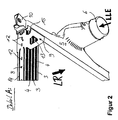
- FIG. 2 shows an isometric detailed representation of a detail A, of a heat exchanger section of a heat exchanger 1 for intercooling with a side part 8 and two Verstungsungswinkeln 9. The same features are provided with the same reference numerals as in Figure 1.
- FIG. 2 shows, compared to FIG. 1, the detail A enlarged.
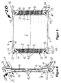
- FIG. 3 shows an isometric view of another exemplary embodiment of a heat exchanger 20 for intercooling with two side parts 28, each with four stiffening angles 29, wherein the stiffening angles 29 have a recess 24 for improved deformation of the stiffening angle.
- stiffening angles 29 are formed integrally with the side part 28.
- one, two, three, four or more than four stiffening angles 29 may be formed integrally with the side part 28.
- one, two, three, four or more than four side parts 28 with the side part 28 at least partially positively and / or cohesively, for example, by soldering, welding, gluing, etc. connected.
- the side part 28, which is integrally formed with one, two, three, four or more than four stiffening angles 29, is usually produced in such a way that first in a first method step, the essential contour and / or the recesses of the side part and the essential contour of at least a stiffening angle 29 are generated.
- the stiffening angle opening 13 from the sheet, which in the future will form the stiffening angle 29, punched out also the side part slots 14 and / or the recess 24 shown in the embodiment of the side part 28 and from the future stiffening angle 29, in particular from the future stiffening angle 29, punched out.
- the side part recesses 12, which are the later attachment of the side member 28 adjacent corrugated fin 4 at this manufacturing step or in another embodiment at a later manufacturing step in the side part 28 can be introduced.
- 8 side part recesses 12 are inserted into the side part 28.
- one to eight or more than eight recesses 12 may be incorporated into the side member 28.
- the side part pocket 23 is inserted into the side part 28.
- the side panel 28 has two side panel flaps.
- the side member 28 may have one or two or more than two side-part pockets 23.
- the tube plate 7 has a number of tubesheet openings 21.
- flat tubes 3 which have at least one flat tube opening 22, inserted into the tubesheet 7 and with this form-fitting manner, for example by a reshaping manufacturing process such as bending or expansion, and / or cohesively, such as soldering, welding, gluing, etc. with the tube sheet 7, connected.
- Figure 4 shows an isometric view of a side member 28 with four stiffening angles 29. The same features are provided with the same reference numerals as in the previous figures.
- FIG. 5 shows a front view of a heat exchanger 20 for intercooling with two side parts 28 each having four stiffening angles 29. Identical features are provided with the same reference number as in the preceding figures.
- FIG. 6 shows an isometric view of a cooling module 60 with a charge air cooler 1, 20 with a coolant radiator 80, with a condenser 70 for an air conditioner and with a fan cowl 90.
- a cooling module 60 with a charge air cooler 1, 20 with a coolant radiator 80, with a condenser 70 for an air conditioner and with a fan cowl 90.
- the same features are provided with the same reference numerals as in the previous figures.
- the cooling module 60 is shown as an exploded view.
- the condenser 70 and the coolant cooler 80 are disposed adjacent to the intercooler 1, 20.
- the condenser 70 and / or the coolant radiator 80 are arranged substantially parallel to the intercooler 1, 20 such that the condenser for an air conditioner on the one side of the intercooler 1, 20 and the coolant radiator 80 on the other side of the intercooler 1, 20 are arranged is.
- the condenser 70 for an air conditioning system has a condenser finned tube block 71 with pipes (not shown) for the flow of refrigerant, in particular flat tubes, and fins for improved heat transfer, in particular corrugated fins. Furthermore, a dryer and / or collecting container is arranged on the capacitor 70 or connected to this form-fitting manner, for example by screwing and / or material fit, for example by soldering or welding or in one embodiment with the capacitor 70. Refrigerant lines 74 lead from a capacitor collecting box unspecified to a valve element 75.
- the condenser 70 has a fifth fastening element, two, three or more than three fifth fastening elements 73, via which the capacitor 70 is positively connected to the heat exchanger 1, 20 for intercooling, For example, by screwing, are fixed and / or material fit, for example by soldering, welding, etc., are attached.
- the condenser 70 is attached to the heat exchanger 1, 20 via third screws.
- the condenser 70 is attached to the heat exchanger 1, 20 for charge air cooling with one to four or more than four third screws 67.
- the coolant cooler 80 has a coolant radiator finned tube block 81 with a number of tubes, in particular flat tubes, and with a number of fins, in particular corrugated fins for improved heat conduction. Furthermore, the coolant cooler 80 has at least one coolant cooler side element 82, in particular two or more than two coolant center side elements 82. Furthermore, the coolant cooler 80 has two water boxes 82. The two water boxes 83 are arranged opposite one another substantially at right angles to the coolant cooler side elements 82. The water boxes 83 are formed in the illustrated embodiment of plastic and / or of a fiber composite material. In another embodiment, the water boxes 83 are formed of a metal such as aluminum.
- the water boxes 83 are in the illustrated embodiment by means of a urformenden manufacturing process such as injection molding, in particular plastic injection molding produced.
- the tubes, in particular flat tubes, of the coolant cooler 80 and the corrugated ribs are formed of a metal, in particular aluminum, which is solder-plated in the illustrated embodiment. Lot is rolled in particular on the aluminum.
- the coolant radiator 80 is in the illustrated embodiment positively connected to the heat exchanger 1, 20 for charge air cooling.
- second screws 66 are inserted through first fastening elements 10 and / or second fastening elements 11 of the intercooler 1, 20 and screwed into the water boxes 83 of the coolant radiator 80.
- a first connecting element 63 by means of first screws 65, in particular by means of two or more than two first screws 65, screwed and positively connected to the vehicle body, for example by screwing
- the intercooler 1, 20 is connected to two first connecting elements 63 to the vehicle body.
- a fan frame 90 is further arranged on the coolant cooler 80.
- the fan cowl 90 has a fan door opening 91, which in the Is designed substantially as a round opening.
- the fan frame 90 is formed in the illustrated embodiment of plastic in another embodiment, it is formed for example of a fiber composite material.
- Figure 7 shows a system with a charge air cooler LLK1, a coolant radiator KMK, a condenser for an air conditioner KO, an exhaust gas heat exchanger AGK on the low pressure side of the turbocharger with single-stage supercharging.
- Identical features are provided with the same reference numerals as in the previous figures.
- the illustrated system shows an internal combustion engine M and a heat exchanger AGK and a valve VT1, which is arranged on the low pressure side, wherein the charging of the charge air takes place in one stage.
- the arrangement on the low-pressure side means that the heat exchanger AGK and / or the valve VP1 are arranged downstream of the first turbine at a low pressure level ND1.
- the charge air is drawn in from the environment and is at the low pressure level ND1 and is then compressed by the compressor V1 to high pressure level HD.
- the charged air heats up and is cooled in the charge air cooler LLK1, which essentially corresponds to the heat exchanger for charge air cooling 1, 20.
- the cooled charge air which also has recirculated exhaust gas, the internal combustion engine M is supplied.
- a condenser for an air conditioner KO Adjacent to the intercooler LLK1, a condenser for an air conditioner KO is disposed.
- a coolant cooler KMK is arranged adjacent to the first charge air cooler LLK1.
- a fan Adjacent to the coolant radiator, a fan is arranged substantially parallel to the coolant radiator KMK. The fan L is used for the intake of air through the condenser and / or through the intercooler LLK1 and / or through the coolant radiator KMK.
- the fan L may be arranged in front of the condenser KO or in front of the intercooler LLK1 or between intercooler LLK1 and the coolant radiator KMK.
- Coolant such as cooling water flows through the motor M and passes through a valve, which is not specified, in the coolant radiator, is cooled there and is fed back into the engine M and flows through it again.
- coolant is fitted on the coolant cooler KMK and is not passed through the coolant cooler KMK.
- the condenser KO refrigerant flows, which is cooled in the condenser KO.
- the valve in particular the exhaust valve VT1 is arranged in front of the exhaust gas heat exchanger AGK.
- the valve VT1 is arranged downstream of the exhaust gas cooler AGK.
- the valve VT1 is integrated into the exhaust gas heat exchanger AGK or formed integrally therewith.
- Figure 8 shows a system with a charge air cooler LLK1, a coolant cooler KMK, a condenser KO for an air conditioner, an exhaust gas cooler AGK, which is arranged on the low pressure side of the turbocharger T2 / V2, wherein the charging takes place in two stages.
- Identical features are provided with the same reference numerals as in the previous figures.
- FIG. 8 has two turbochargers.
- the first turbocharger consists of a first turbine T1, which drives a first compressor V1.
- the first compressor V1 is used for charge air compression.
- the system from FIG. 8 has a second turbocharger with a second turbine T2, in particular an exhaust gas turbine, which drives a second compressor V2 for charge air charging.
- the exhaust gas cooler AGK is arranged on the low-pressure side ND2 of the turbine or of the compressor V2.
- the valve VT1 is arranged in the illustrated embodiment in front of the exhaust gas cooler AGK.
- the valve VT1 is arranged downstream of the exhaust gas cooler AGK.
- the valve VP1 is integrated into the exhaust gas cooler AGK or integrally formed therewith. Charge air is sucked in from the environment. The charge air that has not yet been compressed is admixed with recirculated exhaust gas, for example, and then the compressed charge air and / or the supplied exhaust gas are compressed from the low pressure level ND2 in the compressor V2 to the low pressure level ND1.
- the low pressure level ND1 is higher than the low pressure level ND2, that is, the pressure in the low pressure region ND1 is higher than the pressure in the low pressure region ND1 Low pressure range ND2.
- the charged air and / or the supplied and recirculated exhaust gas is cooled in an intercooler, in particular a charge air cooler LLK2, before it is compressed from the low pressure level ND1 by means of the compressor V1 to the high pressure level HD.
- the high pressure level HD there is a higher pressure than in the low pressure range ND1.
- the compressed charge air and / or the recirculated exhaust gas in the charge air cooler LLK1 is cooled before it is supplied to the motor M.
- Figure 9 shows a system with a charge air cooler LLK1, a coolant cooler KMK, a condenser for an air conditioner KO, an exhaust gas cooler AGK, which is arranged on the high pressure side, ie on the high pressure side with the pressure level HD of the turbine, in particular the first turbine T1. Charging takes place in one stage.
- Identical features are provided with the same reference numerals as in the previous figures.
- valve VT1 After flowing through the engine M1, a part of the exhaust gas is branched off and passed through a valve VT1 through an exhaust gas cooler AGK, cooled therein and the charge air cooled in the charge air cooler LLK1 mixed in as required, the mixture then being fed back to the engine M.
- the valve VT1 can also be arranged downstream of the exhaust gas cooler AGK or integrated into the exhaust gas cooler AGK or be formed integrally therewith.
- FIG. 10 shows a system with a charge air cooler LLK 1, 20, a coolant cooler KMK 80, a condenser KO 70, an exhaust gas cooler AGK, wherein the exhaust gas cooler on the high pressure side of the first turbine T1 is arranged at the high pressure level HD.
- the system is essentially the same as the system in FIG. 9, except that the charging of the charge air sucked in from the environment takes place in two stages. Identical features are provided with the same reference numerals as in the previous figures.
- the charge air drawn in from the environment is at the low pressure level ND2 and is then compressed in the second compressor V2 to the low pressure level ND1.
- the low pressure level ND1 has a higher pressure than the low pressure level ND2.
- the compressed charge air is cooled in an intercooler, in particular in a charge air cooler LLK2 and then compressed with the first compressor V1 to the high pressure level HD.
- the charge air is cooled in the first charge air cooler LLK1 1, 20 and, if necessary, mixed with recirculated exhaust gas and then fed to the motor M.
Landscapes
- Engineering & Computer Science (AREA)
- Physics & Mathematics (AREA)
- Thermal Sciences (AREA)
- Chemical & Material Sciences (AREA)
- Combustion & Propulsion (AREA)
- Mechanical Engineering (AREA)
- General Engineering & Computer Science (AREA)
- Heat-Exchange Devices With Radiators And Conduit Assemblies (AREA)
Applications Claiming Priority (1)
| Application Number | Priority Date | Filing Date | Title |
|---|---|---|---|
| DE102006017610.3A DE102006017610B4 (de) | 2006-04-12 | 2006-04-12 | Wärmetauscher zur Ladeluftkühlung für Kraftfahrzeuge, System |
Publications (1)
| Publication Number | Publication Date |
|---|---|
| EP1845242A2 true EP1845242A2 (fr) | 2007-10-17 |
Family
ID=38038919
Family Applications (1)
| Application Number | Title | Priority Date | Filing Date |
|---|---|---|---|
| EP07007157A Withdrawn EP1845242A2 (fr) | 2006-04-12 | 2007-04-05 | Échangeur de chaleur pour refroidissement d'air d'admission pour véhicule et système |
Country Status (2)
| Country | Link |
|---|---|
| EP (1) | EP1845242A2 (fr) |
| DE (1) | DE102006017610B4 (fr) |
Cited By (3)
| Publication number | Priority date | Publication date | Assignee | Title |
|---|---|---|---|---|
| WO2009062697A1 (fr) * | 2007-11-12 | 2009-05-22 | Behr Gmbh & Co. Kg | Dispositif de refroidissement des gaz d'échappement pour véhicule à moteur |
| WO2010118848A1 (fr) * | 2009-04-17 | 2010-10-21 | Behr Gmbh & Co. Kg | Canal d'air de suralimentation pour moteur à combustion interne |
| CN104912650A (zh) * | 2014-12-26 | 2015-09-16 | 无锡久盛换热器有限公司 | 应用于大型重卡的中冷器 |
Families Citing this family (2)
| Publication number | Priority date | Publication date | Assignee | Title |
|---|---|---|---|---|
| DE102014101386A1 (de) | 2014-02-05 | 2015-08-06 | Dr. Ing. H.C. F. Porsche Aktiengesellschaft | Ladeluftkühler |
| SE538914C2 (en) | 2014-12-11 | 2017-02-14 | Scania Cv Ab | A charge air cooler tank with an integrated protective structure |
Family Cites Families (11)
| Publication number | Priority date | Publication date | Assignee | Title |
|---|---|---|---|---|
| DE3303986A1 (de) | 1983-02-05 | 1984-08-09 | Süddeutsche Kühlerfabrik Julius Fr. Behr GmbH & Co KG, 7000 Stuttgart | Wasser/luft-kuehler fuer wassergekuehlte verbrennungskraftmaschinen, insbesondere von nutzfahrzeugen |
| US5095882A (en) | 1990-05-29 | 1992-03-17 | Paccar Inc. | Cleanable air-to-air cooling system |
| GB2303437A (en) | 1995-06-12 | 1997-02-19 | Ford Motor Co | Stress relief in heat exchangers |
| US6029345A (en) | 1995-11-13 | 2000-02-29 | Alliedsignal Inc. | Radiator, charge air cooler and condenser mounting method |
| US6412547B1 (en) | 2000-10-04 | 2002-07-02 | Modine Manufacturing Company | Heat exchanger and method of making the same |
| DE10255011A1 (de) | 2002-04-09 | 2003-10-30 | Behr Gmbh & Co | Wärmeübertragereinheit, insbesondere für ein Kraftfahrzeug |
| SE525967C2 (sv) | 2003-10-30 | 2005-06-07 | Scania Cv Abp | Kylanordning |
| DE102005004778A1 (de) | 2004-02-01 | 2005-08-18 | Behr Gmbh & Co. Kg | Anordnung zur Kühlung von Abgas und Ladeluft |
| EP1716378B1 (fr) | 2004-02-02 | 2008-02-20 | Behr GmbH & Co. KG | Tole laterale de radiateur |
| FR2873434B1 (fr) | 2004-07-20 | 2017-12-29 | Valeo Thermique Moteur Sa | Echangeur de chaleur muni de joues |
| DE102006016066A1 (de) | 2005-04-05 | 2006-10-19 | Behr Gmbh & Co. Kg | Wärmeübertrager, insbesondere für ein Kraftfahrzeug |
-
2006
- 2006-04-12 DE DE102006017610.3A patent/DE102006017610B4/de not_active Expired - Fee Related
-
2007
- 2007-04-05 EP EP07007157A patent/EP1845242A2/fr not_active Withdrawn
Cited By (12)
| Publication number | Priority date | Publication date | Assignee | Title |
|---|---|---|---|---|
| WO2009062697A1 (fr) * | 2007-11-12 | 2009-05-22 | Behr Gmbh & Co. Kg | Dispositif de refroidissement des gaz d'échappement pour véhicule à moteur |
| CN101855429A (zh) * | 2007-11-12 | 2010-10-06 | 贝洱两合公司 | 车用废气冷却器 |
| JP2011503500A (ja) * | 2007-11-12 | 2011-01-27 | ベール ゲーエムベーハー ウント コー カーゲー | 自動車用の排ガス冷却器 |
| US8794300B2 (en) | 2007-11-12 | 2014-08-05 | Behr Gmbh & Co. Kg | Exhaust gas cooler for a motor vehicle |
| US20140299294A1 (en) * | 2007-11-12 | 2014-10-09 | Behr Gmbh & Co. Kg | Exhaust gas cooler for a motor vehicle |
| WO2010118848A1 (fr) * | 2009-04-17 | 2010-10-21 | Behr Gmbh & Co. Kg | Canal d'air de suralimentation pour moteur à combustion interne |
| WO2010118847A1 (fr) * | 2009-04-17 | 2010-10-21 | Behr Gmbh & Co. Kg | Canal d'air de suralimentation pour moteur à combustion interne |
| CN102459840A (zh) * | 2009-04-17 | 2012-05-16 | 贝洱两合公司 | 用于内燃机的增压空气管道 |
| US8733327B2 (en) | 2009-04-17 | 2014-05-27 | Behr Gmbh & Co. Kg | Charge air duct for an internal combustion engine |
| US8813729B2 (en) | 2009-04-17 | 2014-08-26 | Behr Gmbh & Co. Kg | Charge air duct for an internal combustion engine |
| CN102459840B (zh) * | 2009-04-17 | 2015-07-01 | 贝洱两合公司 | 用于内燃机的增压空气管道 |
| CN104912650A (zh) * | 2014-12-26 | 2015-09-16 | 无锡久盛换热器有限公司 | 应用于大型重卡的中冷器 |
Also Published As
| Publication number | Publication date |
|---|---|
| DE102006017610B4 (de) | 2020-08-06 |
| DE102006017610A1 (de) | 2007-10-18 |
Similar Documents
| Publication | Publication Date | Title |
|---|---|---|
| EP1911946B1 (fr) | Dispositif de refroidissement de l'air de suralimentation pour un moteur à combustion interne, système doté d'un dispositif de refroidissement de l'air de suralimentation | |
| EP2628896B1 (fr) | Dispositif de transfert de chaleur | |
| EP1985953B1 (fr) | Echangeur thermique, en particulier destiné au refroidissement des gaz d'échappement, procédé d'utilisation d'un tel échangeur et système comprenant un refroidisseur EGR | |
| EP2501912B1 (fr) | Tuyau d'aspiration pour un moteur à combustion interne | |
| EP1279805B1 (fr) | Refroidisseur de l'air de charge aéroréfrigérée | |
| EP1989432B1 (fr) | Soupape de regulation de l'ecoulement de gaz d'echappement d'un moteur a combustion interne, echangeur de chaleur destine au refroidissement des gaz d'echappement, systeme dote d'au moins une soupape et d'au moins un echangeur de chaleur | |
| EP2765286B1 (fr) | Dispositif d'alimentation en air frais d'un moteur à combustion interne | |
| DE102017208494B4 (de) | Krümmer-integrierter zwischenkühler mit strukturkern | |
| EP2655828A1 (fr) | Tube aspirant avec refroidisseur d'air de suralimentation intégré | |
| WO2008104402A1 (fr) | Dispositif de refroidissement d'air de suralimentation, système de suralimentation par turbocompresseur et/ou de refroidissement d'air de suralimentation et procédé de refroidissement d'air de suralimentation | |
| DE102007010123A1 (de) | Vorrichtung zur Ladeluftkühlung, System zur Turboaufladung und/oder Ladeluftkühlung, Verfahren zur Ladeluftkühlung | |
| DE102006048667A1 (de) | Wärmeübertrageranordnung und Verfahren zur Wärmeübertragung | |
| DE102008014373A1 (de) | Strömungskanal, Wärmetauscher, Abgasrückführsystem, Ladeluft-Zuführsystem, Verwendung eines Wärmetauschers | |
| DE102007031824A1 (de) | Wärmetauscher | |
| EP1657512B1 (fr) | Echangeur de chaleur avec un profilé ouvert en tant que boîtier | |
| EP1845242A2 (fr) | Échangeur de chaleur pour refroidissement d'air d'admission pour véhicule et système | |
| EP1690056B1 (fr) | Echangeur thermique conçu en particulier pour des vehicules automobiles | |
| EP1956212A1 (fr) | Agencement d'un refroidisseur d'air de suralimentation dans un système d'aspiration d'un moteur à combustion interne | |
| DE19909672B4 (de) | Kühlmodul | |
| EP2048345B1 (fr) | Echangeur thermique, notamment destiné au refroidissement des gaz d'échappement | |
| EP2029953A1 (fr) | Échangeur thermique, notamment refroidisseur d'air de suralimentation, à fond tubulaire renforcé | |
| EP3097379B1 (fr) | Échangeur de chaleur | |
| EP1938035A1 (fr) | Echangeur thermique conçu en particulier pour des vehicules automobiles | |
| EP3303969B1 (fr) | Combinaison d'un échangeur de chaleur et d'au moins deux éléments de raccordement pouvant être raccordés alternativement à l'échangeur de chaleur | |
| DE102005028510A1 (de) | Verstellbarer innerer Wärmeübertrager |
Legal Events
| Date | Code | Title | Description |
|---|---|---|---|
| PUAI | Public reference made under article 153(3) epc to a published international application that has entered the european phase |
Free format text: ORIGINAL CODE: 0009012 |
|
| AK | Designated contracting states |
Kind code of ref document: A2 Designated state(s): AT BE BG CH CY CZ DE DK EE ES FI FR GB GR HU IE IS IT LI LT LU LV MC MT NL PL PT RO SE SI SK TR |
|
| AX | Request for extension of the european patent |
Extension state: AL BA HR MK YU |
|
| STAA | Information on the status of an ep patent application or granted ep patent |
Free format text: STATUS: THE APPLICATION IS DEEMED TO BE WITHDRAWN |
|
| 18D | Application deemed to be withdrawn |
Effective date: 20091103 |