EP1635165A2 - Dispositif de formation d'images fluorométriques - Google Patents
Dispositif de formation d'images fluorométriques Download PDFInfo
- Publication number
- EP1635165A2 EP1635165A2 EP05111237A EP05111237A EP1635165A2 EP 1635165 A2 EP1635165 A2 EP 1635165A2 EP 05111237 A EP05111237 A EP 05111237A EP 05111237 A EP05111237 A EP 05111237A EP 1635165 A2 EP1635165 A2 EP 1635165A2
- Authority
- EP
- European Patent Office
- Prior art keywords
- specimen
- imaging apparatus
- light
- fluorometric imaging
- excitation light
- Prior art date
- Legal status (The legal status is an assumption and is not a legal conclusion. Google has not performed a legal analysis and makes no representation as to the accuracy of the status listed.)
- Withdrawn
Links
Images


Classifications
-
- G—PHYSICS
- G02—OPTICS
- G02B—OPTICAL ELEMENTS, SYSTEMS OR APPARATUS
- G02B21/00—Microscopes
- G02B21/0004—Microscopes specially adapted for specific applications
- G02B21/002—Scanning microscopes
- G02B21/0024—Confocal scanning microscopes (CSOMs) or confocal "macroscopes"; Accessories which are not restricted to use with CSOMs, e.g. sample holders
- G02B21/0052—Optical details of the image generation
- G02B21/0076—Optical details of the image generation arrangements using fluorescence or luminescence
-
- G—PHYSICS
- G01—MEASURING; TESTING
- G01N—INVESTIGATING OR ANALYSING MATERIALS BY DETERMINING THEIR CHEMICAL OR PHYSICAL PROPERTIES
- G01N21/00—Investigating or analysing materials by the use of optical means, i.e. using sub-millimetre waves, infrared, visible or ultraviolet light
- G01N21/62—Systems in which the material investigated is excited whereby it emits light or causes a change in wavelength of the incident light
- G01N21/63—Systems in which the material investigated is excited whereby it emits light or causes a change in wavelength of the incident light optically excited
- G01N21/64—Fluorescence; Phosphorescence
- G01N21/6428—Measuring fluorescence of fluorescent products of reactions or of fluorochrome labelled reactive substances, e.g. measuring quenching effects, using measuring "optrodes"
-
- G—PHYSICS
- G01—MEASURING; TESTING
- G01N—INVESTIGATING OR ANALYSING MATERIALS BY DETERMINING THEIR CHEMICAL OR PHYSICAL PROPERTIES
- G01N21/00—Investigating or analysing materials by the use of optical means, i.e. using sub-millimetre waves, infrared, visible or ultraviolet light
- G01N21/62—Systems in which the material investigated is excited whereby it emits light or causes a change in wavelength of the incident light
- G01N21/63—Systems in which the material investigated is excited whereby it emits light or causes a change in wavelength of the incident light optically excited
- G01N21/64—Fluorescence; Phosphorescence
- G01N21/645—Specially adapted constructive features of fluorimeters
- G01N21/6452—Individual samples arranged in a regular 2D-array, e.g. multiwell plates
-
- G—PHYSICS
- G01—MEASURING; TESTING
- G01N—INVESTIGATING OR ANALYSING MATERIALS BY DETERMINING THEIR CHEMICAL OR PHYSICAL PROPERTIES
- G01N21/00—Investigating or analysing materials by the use of optical means, i.e. using sub-millimetre waves, infrared, visible or ultraviolet light
- G01N21/62—Systems in which the material investigated is excited whereby it emits light or causes a change in wavelength of the incident light
- G01N21/63—Systems in which the material investigated is excited whereby it emits light or causes a change in wavelength of the incident light optically excited
- G01N21/64—Fluorescence; Phosphorescence
- G01N21/645—Specially adapted constructive features of fluorimeters
- G01N21/6456—Spatial resolved fluorescence measurements; Imaging
- G01N21/6458—Fluorescence microscopy
-
- G—PHYSICS
- G02—OPTICS
- G02B—OPTICAL ELEMENTS, SYSTEMS OR APPARATUS
- G02B21/00—Microscopes
- G02B21/0004—Microscopes specially adapted for specific applications
- G02B21/002—Scanning microscopes
- G02B21/0024—Confocal scanning microscopes (CSOMs) or confocal "macroscopes"; Accessories which are not restricted to use with CSOMs, e.g. sample holders
- G02B21/0036—Scanning details, e.g. scanning stages
- G02B21/0044—Scanning details, e.g. scanning stages moving apertures, e.g. Nipkow disks, rotating lens arrays
-
- G—PHYSICS
- G02—OPTICS
- G02B—OPTICAL ELEMENTS, SYSTEMS OR APPARATUS
- G02B21/00—Microscopes
- G02B21/16—Microscopes adapted for ultraviolet illumination ; Fluorescence microscopes
-
- G—PHYSICS
- G01—MEASURING; TESTING
- G01N—INVESTIGATING OR ANALYSING MATERIALS BY DETERMINING THEIR CHEMICAL OR PHYSICAL PROPERTIES
- G01N21/00—Investigating or analysing materials by the use of optical means, i.e. using sub-millimetre waves, infrared, visible or ultraviolet light
- G01N21/62—Systems in which the material investigated is excited whereby it emits light or causes a change in wavelength of the incident light
- G01N21/63—Systems in which the material investigated is excited whereby it emits light or causes a change in wavelength of the incident light optically excited
- G01N21/64—Fluorescence; Phosphorescence
- G01N21/645—Specially adapted constructive features of fluorimeters
- G01N2021/6463—Optics
- G01N2021/6478—Special lenses
-
- G—PHYSICS
- G01—MEASURING; TESTING
- G01N—INVESTIGATING OR ANALYSING MATERIALS BY DETERMINING THEIR CHEMICAL OR PHYSICAL PROPERTIES
- G01N21/00—Investigating or analysing materials by the use of optical means, i.e. using sub-millimetre waves, infrared, visible or ultraviolet light
- G01N21/62—Systems in which the material investigated is excited whereby it emits light or causes a change in wavelength of the incident light
- G01N21/63—Systems in which the material investigated is excited whereby it emits light or causes a change in wavelength of the incident light optically excited
- G01N21/64—Fluorescence; Phosphorescence
- G01N2021/6491—Measuring fluorescence and transmission; Correcting inner filter effect
Definitions
- the present invention relates to a biochip reader for reading weak fluorescent light produced by exciting samples on a biochip with excitation. light. More specifically, the present invention relates to improvements made to accelerate measurement, simplify the apparatus, reduce damage to samples, flatten the intensity distribution within the spot of light produced when a beam of excitation laser light is condensed with a microlens, and enable free definition of the pitch at which samples on a biochip are arranged.
- the present invention further relates to a fluoromatric imaging apparatus for measuring biochips of DNA, RNA, protein, and the like and, more specifically, to the positioning of specimens.
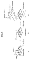
- FIG. 1 is a conceptual schematic view showing one example of a conventional epi-illuminated biochip reader.
- this reader reads samples made, as shown in FIG. 1(b), by hybridizing unknown gene ⁇ with biochip 6 wherein a plurality of DNA molecules (genes) A, B, C ..., with a known sequence are arranged on substrate 5 as shown in FIG. I(a).
- a mechanism as discussed above is the same as the prior art mechanism of FIG. 2 shown in the Patent Application 09/562,317 filed in the US by the inventors mentioned in the application concerned.
- light (laser light) from light source 1 is collimated by lens 2, passes through dichroic mirror 4, and is condensed by lens 3 onto specimen 6 (biochip 6 in this example).
- Light returning from biochip 6 reverts to parallel light by means of lens 3, reflects off dichroic mirror 4, and forms an image on detector 9a by means of lens 8.
- a stage (not shown in the figure) loaded with biochip 6 is moved in the XY direction by a drive means, so that the surface of biochip 6 is scanned and the image thereof obtained.
- An image of the biochip's surface is obtained by scanning across the stage with a single spot of light being irradiated at biochip 6.
- This method has the disadvantage that the mechanism for moving the stage is too complex and requires extra time before the image is obtained.
- Another disadvantage is that the intensity of light beams must be high enough for the method to be effective. Higher intensities of light may result in the problem, however, of bleaching of the fluorescent dyes of samples.
- An object of the present invention is to solve the aforementioned problems by providing a biochip reader that eliminates the need for moving a stage on which samples are mounted, and avoids the risk of bleaching of fluorescent dyes.
- the biochip reader features a simple construction, making it possible to accelerate measurement, simplify the apparatus, reduce damage to samples, and flatten the intensity distribution within the spot of light produced when rays of excitation laser light are condensed with a microlens.
- the biochip reader makes it possible to freely define the pitch at which samples on a biochip are arranged, and measure even weak light emitted from the samples.
- fluorometric imaging apparatuses for measuring fluorescent images using, for example, an epi-illuminated confocal laser microscope have been well known among those skilled in the art.
- the epi-illuminated confocal laser microscope there is the confocal optical scanner described in the US Patent 5,428,475.
- a dedicated positioning means is required. Although no such positioning means is shown for the aforementioned confocal optical scanner, the means can be materialized by applying, for example, the positioning method described on page 19 of the BME journal (Vol. 11, No. 10 (1997)) of the Japanese Society for Medical and Biological Engineering.
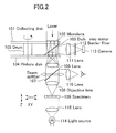
- FIG. 2 is a schematic view showing one embodiment of the aforementioned fluorometric imaging apparatus.
- Beams of laser light (excitation light) are focused using a plurality of microlenses 102 formed on collecting disk 101, and condensed into the pinholes of pinhole disk 104.
- Collecting disk 101 and pinhole disk 104 are coupled with each other through drum 105, so that the pinholes are positioned at the focal points of the plurality of microlens, and the two disks rotate in an integral manner.
- Excitation light projected through pinholes is collimated with lens 106, and then condensed onto specimen 109 with objective lens 108. Fluorescent light is produced when a fluorescent substance attached to specimen 109 is irradiated with excitation light. The fluorescent light thus produced then passes through objective lens 108 and lens 106, and converges onto the pinholes of pinhole disk 104, where fluorescent images of the specimen's surface are formed.
- Fluorescent light that has passed through the pinholes reflects off dichroic mirror 103 located between collecting disk 101 and pinhole disk 104, passes through lens 111 and barrier filter 112, and forms an image on the photoreceptive surface of camera 113.
- Barrier filter 112 allows fluorescent light to pass therethrough but rejects background light with wavelengths other than that of the fluorescent light.
- beam splitter 107 is moved out of the optical path at the time of fluorescence measurement.
- a spot of light is projected onto specimen 109 from the illumination system located underneath specimen 109. Then, a spot image of specimen 109's top surface is visually observed through the observation system.
- the illumination system is configured so that light from light source 114 is collimated with lens 115, as shown in the figure, and then irradiated at specimen 108 as Koehler illumination.
- specimen 109 When specimen 109 is positioned in the XY direction, specimen 109 is moved in the XY direction by means of a movement mechanism, in order to determine the area of the specimen to be observed.
- a movement mechanism can be used for this purpose and, therefore, the configuration of the mechanism is not explained and illustrated in this example.
- Fluorometric imaging apparatuses are often used for such applications as fluorescence-based observation of the movement of specific proteins inside a cell. In this application, however, it is not possible to observe the entire cell by means of fluorescence alone. Since the method of this example permits the entire cell to be observed with transmitted light, it is easy to move the cell to the center of the screen.
- the specimen When positioning specimen 109 in the Z direction, the specimen is moved in the Z direction (the movement mechanism is not shown in the figure) so that the specimen is placed in the position where images being observed are sharpest and most crisp.
- An object of the present invention is to solve the aforementioned problems by providing a fluorometric imaging apparatus that is simple in configuration and inexpensive, and permits easy positioning of specimens.
- the present invention provides a scanless biochip reader for reading the image information of samples using a photoreceptor device, by irradiating a corresponding beam of excitation light at each site of a biochip on which a plurality of the samples are arranged at equal pitches, the biochip reader comprising:
- excitation light from the light source is transformed into a multibeam by means of microlenses and multiple beams are simultaneously irradiated at the specimen through the zoom lens. Accordingly, there is no need to perform optical scanning as has been conventionally done, thus simplifying the apparatus configuration.
- excitation light used for the biochip reader of the present invention can be made weaker, in inverse proportion to the number of beams, than that used for optical scanning. Since there is no need for irradiating high-intensity laser light as has been conventionally done, the apparatus of the present invention avoids the risk of bleaching of fluorescent dyes. In addition, it is possible to measure even weak fluorescent light.
- the biochip reader of the present invention uses a zoom lens, it is possible to easily change the pitch between beams for irradiating specimens. This means that the biochip reader offers another advantage that even if sites of a specimen are arranged at an arbitrary pitch, it is possible to make the pitch between the sites of the specimen agree with the pitch between beams.
- the present invention provides a fluorometric imaging apparatus for detecting the image of a specimen by irradiating excitation light at samples on the specimen arranged in a two-dimensional manner and measuring fluorescent light produced from a fluorescent substance attached to the specimen, the fluorometric imaging apparatus comprising:
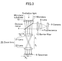
- FIG. 3 is a schematic view showing one embodiment of the biochip reader in accordance with the present invention.
- elements identical to those shown in FIG. 1 are referenced alike and excluded from the description hereinafter presented.
- numeral 10 denotes a microlens substrate
- numeral 11 denotes a microlens
- numeral 12 denotes a barrier filter
- numeral 20 denotes a telecentric zoom lens.
- microlens substrate 10 On microlens substrate 10, a plurality of microlenses 11 are arranged at equal pitch P 1 .
- Zoom lens 20 comprises lens 21 with focal length f 1 and lens 21 with focal length f 2 , where both focal length f 1 and focal length f 2 are variable. Zoom lens 20 is located between dichroic mirror 4 and specimen 6.
- each of lenses 21 and 22 is illustrated as a single lens for the sake of convenience, these lenses are usually composed of multiple lenses.
- Barrier filter 12 which is located between dichroic mirror 4 and lens 8, has the effect of letting fluorescent light arising from specimen 6 to pass through and rejecting light with wavelengths other than that of the fluorescent light.
- excitation light projected from the topside of microlens substrate 10 is transformed into a multibeam by means of a plurality of microlenses 11, and perpendicularly enters zoom lens 20.
- light transformed into a beam with microlens 11 converges onto the focal point of microlens 11 (the pitch between points of convergence is defined as P 1 ), and then diverges again and enters zoom lens 20.
- Each beam vertically projected from the lens 22 of zoom lens 20 is condensed (the pitch between points of convergence is defined as P 2 ) and spot-irradiates the surface of specimen 6.
- the zoom lens may be a non-telecentric lens, as shown in FIG. 4.
- excitation light beams projected from the zoom lens do not vertically enter the specimen's surface, but diverge as shown in FIG. 4(a) or converge as shown in FIG. 4(b). This modification does not pose any problem provided the beams are for the purpose of exciting the biochip.
- the portion ranging from dichroic mirror 4 to camera 9 of the apparatus of FIG. 3 may be located between lens 22 and specimen 6.
- the excitation light beams may be defocused to irradiate the specimen with a uniform energy of luminance.
- the present invention offers the following advantages.
- FIG. 5 is a schematic view showing one embodiment of the fluorometric imaging apparatus in accordance with the present invention.
- elements identical to those shown in FIG. 2 are referenced alike and excluded from the description hereinafter presented.
- FIG. 5 differs from FIG. 2 in that the illumination system composed of light source 114 and lens 115 and the spots-of-light observation system composed of beam splitter 107 and lens 110 are excluded, and lens 121 and camera 122 having a two-dimensional photoreceptor device are included instead.
- Lens 121 condenses excitation light passing through specimen 109 onto the photoreceptive surface of camera 122.
- samples on the specimen arranged in a two-dimensional manner are irradiated with multiple beams of excitation light, enabling the image of the specimen to be observed on camera 122.
- a conventional confocal fluorescence microscope does not make use of excitation light passing through specimen 109.
- the present invention makes use of the light in order to position specimen 109. This is one of the characteristics of the present invention.
- Positioning of specimen 109 in the XY direction is performed while checking images observed on camera 122.
- Positioning in the Z direction can be achieved by means of an auto-focusing mechanism (not shown in the figure). Note that the present invention is not limited to moving only the specimen in the X, Y and Z directions. Alternatively, the excitation light side of the apparatus may be moved by moving objective lens 108 in the X, Y and Z directions.
- an auto-focusing mechanism based on, for example, a maximum contrast method, it is possible to adopt a mechanism for automatically controlling the movement of the specimen in the Z direction so that the difference between the darkest and brightest points in images observed on camera 122 is maximum.
- FIG. 6 is a schematic view showing another embodiment of the present invention.
- FIG. 6 shows a non-optically-scanned (scanless) microscope.
- elements identical to those shown in FIG. 5 are referenced alike and excluded from the explanation hereafter presented.
- numeral 10 denotes a microlens substrate where a plurality of microlenses 11 are arranged on a transparent substrate.
- Numeral 109 denotes a specimen, for which a DNA chip on which samples are arranged in a two-dimensional manner or a DNA microarray, for example, may be adopted. In this case, each microlens 11 and each site of specimen 109 are arranged in a one-to-one positional relationship.
- each laser beam (excitation light) projected from the topside of microlens substrate 21 is condensed by each microlens 22, and each site of specimen 109 is irradiated with the condensed laser beam.
- the subsequent steps are the same as those explained with reference to FIG. 5. That is, fluorescent light emitted from specimen 109 is reflected by dichroic mirror 103, enters lens 111 and is condensed thereby, passes through barrier filter 112, and forms an image on the photoreceptor device of camera 113.
- excitation light passing through specimen 109 converges onto the surface of the photoreceptor device of camera 132 by means of lens 131.
- Specimen 109 is positioned according to images observed on the photoreceptor device surface. Specimen positioning is the same as in the case of FIG. 5. That is, positioning in the XY direction is performed while checking images observed on camera 132. For positioning in the Z direction, the specimen is automatically positioned by means of an auto-focusing mechanism that functions according to observed images.
- markers for XYZ positioning may be provided on specimen 109, so that positioning in the XYZ directions is achieved on the basis of these markers.
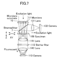
- FIG. 7 is a schematic view showing yet another embodiment in accordance with the present invention. Unlike the scanless reflecting fluorescence microscope of FIG. 6, the apparatus of FIG. 7 is a scanless transmission fluorescence microscope. In FIG. 7, elements identical to those shown in FIG. 6 are referenced alike.
- Fluorescent light produced in specimen 109 passes therethrough to enter lens 141, wherein the light is collimated, and enters lens 142.
- other types of light (known as background light) with wavelengths other than that of the fluorescent light are removed by barrier filter 112 inserted between lenses 141 and 142.
- the fluorescent light wherefrom background light has been removed is condensed by lens 142 and forms an image on the photoreceptor device surface of camera 113.
- Catoptric light (excitation light), which reflects from specimen 109 and is used to position the specimen, reflects off beam splitter 7 to enter lens 131, whereby the light is focused, and converges onto the photoreceptor device surface of camera 132.
- specimen positioning can be achieved in the same way as in the case of FIG. 6, according to images of the specimen's surface observed on the photoreceptor device.
Landscapes
- Physics & Mathematics (AREA)
- Chemical & Material Sciences (AREA)
- Health & Medical Sciences (AREA)
- General Physics & Mathematics (AREA)
- Analytical Chemistry (AREA)
- Immunology (AREA)
- Optics & Photonics (AREA)
- Life Sciences & Earth Sciences (AREA)
- Biochemistry (AREA)
- General Health & Medical Sciences (AREA)
- Nuclear Medicine, Radiotherapy & Molecular Imaging (AREA)
- Pathology (AREA)
- Chemical Kinetics & Catalysis (AREA)
- Investigating, Analyzing Materials By Fluorescence Or Luminescence (AREA)
- Microscoopes, Condenser (AREA)
- Length Measuring Devices By Optical Means (AREA)
Applications Claiming Priority (3)
| Application Number | Priority Date | Filing Date | Title |
|---|---|---|---|
| JP2001241862A JP2003057557A (ja) | 2001-08-09 | 2001-08-09 | バイオチップ読取装置 |
| JP2001241863A JP3968629B2 (ja) | 2001-08-09 | 2001-08-09 | 蛍光画像計測装置 |
| EP02016363A EP1283416A3 (fr) | 2001-08-09 | 2002-07-25 | Lecteur de biopuces et dispositif de formation d'images fluorométriques |
Related Parent Applications (1)
| Application Number | Title | Priority Date | Filing Date |
|---|---|---|---|
| EP02016363A Division EP1283416A3 (fr) | 2001-08-09 | 2002-07-25 | Lecteur de biopuces et dispositif de formation d'images fluorométriques |
Publications (2)
| Publication Number | Publication Date |
|---|---|
| EP1635165A2 true EP1635165A2 (fr) | 2006-03-15 |
| EP1635165A3 EP1635165A3 (fr) | 2006-03-22 |
Family
ID=26620262
Family Applications (2)
| Application Number | Title | Priority Date | Filing Date |
|---|---|---|---|
| EP02016363A Ceased EP1283416A3 (fr) | 2001-08-09 | 2002-07-25 | Lecteur de biopuces et dispositif de formation d'images fluorométriques |
| EP05111237A Withdrawn EP1635165A3 (fr) | 2001-08-09 | 2002-07-25 | Dispositif de formation d'images fluorométriques |
Family Applications Before (1)
| Application Number | Title | Priority Date | Filing Date |
|---|---|---|---|
| EP02016363A Ceased EP1283416A3 (fr) | 2001-08-09 | 2002-07-25 | Lecteur de biopuces et dispositif de formation d'images fluorométriques |
Country Status (2)
| Country | Link |
|---|---|
| US (3) | US20030031596A1 (fr) |
| EP (2) | EP1283416A3 (fr) |
Cited By (1)
| Publication number | Priority date | Publication date | Assignee | Title |
|---|---|---|---|---|
| EP2203735A4 (fr) * | 2007-10-29 | 2012-03-21 | Ca Nat Research Council | Procédé et appareil de détection de la fluorescence émise par des fluorophores liés à des particules confinées dans des pièges à particules |
Families Citing this family (24)
| Publication number | Priority date | Publication date | Assignee | Title |
|---|---|---|---|---|
| US7292333B2 (en) * | 2003-06-24 | 2007-11-06 | Corning Incorporated | Optical interrogation system and method for 2-D sensor arrays |
| US7057720B2 (en) * | 2003-06-24 | 2006-06-06 | Corning Incorporated | Optical interrogation system and method for using same |
| DE10350918B3 (de) | 2003-10-31 | 2005-04-14 | Evotec Technologies Gmbh | Vorrichtung und Verfahren zur Messung der Transmission eines Objekts |
| JP4370900B2 (ja) * | 2003-12-22 | 2009-11-25 | 横河電機株式会社 | バイオチップ基板保持方法およびバイオチップ読取装置 |
| US7247494B2 (en) * | 2004-02-27 | 2007-07-24 | Agilent Technologies, Inc. | Scanner with array anti-degradation features |
| DE602005004332T2 (de) | 2004-06-17 | 2009-01-08 | Cadent Ltd. | Verfahren zum Bereitstellen von Daten im Zusammenhang mit der Mundhöhle |
| JP2006078772A (ja) * | 2004-09-09 | 2006-03-23 | Yokogawa Electric Corp | 共焦点顕微鏡 |
| JP2008524578A (ja) * | 2004-12-17 | 2008-07-10 | コーニンクレッカ フィリップス エレクトロニクス エヌ ヴィ | マルチスポット調査装置 |
| US8504140B2 (en) * | 2008-04-08 | 2013-08-06 | Bruker Biospin Corporation | Apparatus and method for fluorescence imaging and tomography using spatially structured illumination |
| JP5095935B2 (ja) * | 2005-11-15 | 2012-12-12 | オリンパス株式会社 | 顕微鏡装置 |
| US7560711B2 (en) * | 2006-08-09 | 2009-07-14 | King Fahd University Of Petroleum And Minerals | Multiple fingerprinting of petroleum oils using normalized time-resolved laser-induced fluorescence spectral subtractions |
| US20080277595A1 (en) * | 2007-05-10 | 2008-11-13 | Pacific Biosciences Of California, Inc. | Highly multiplexed confocal detection systems and methods of using same |
| EP2150806A4 (fr) * | 2007-05-10 | 2013-01-02 | Pacific Biosciences California | Procédés et systèmes d'analyse de matière fluorescente à autofluorescence limitée |
| US20100167413A1 (en) * | 2007-05-10 | 2010-07-01 | Paul Lundquist | Methods and systems for analyzing fluorescent materials with reduced autofluorescence |
| WO2009002225A2 (fr) * | 2007-06-25 | 2008-12-31 | Closed Company 'molecular-Medicine Technologies' | Dispositif multifonctions de diagnostic et procédé de test pour objets biologiques |
| US7994485B2 (en) * | 2008-04-08 | 2011-08-09 | Carestream Health, Inc. | Apparatus and method for fluorescence measurements using spatially structured illumination |
| US8796011B2 (en) * | 2008-10-20 | 2014-08-05 | Samsung Electronics Co., Ltd. | Apparatus for fabricating and optically detecting biochip |
| KR101022769B1 (ko) * | 2008-10-20 | 2011-03-17 | 삼성전자주식회사 | 바이오칩용 광검출 장치 |
| CA2741105C (fr) | 2008-10-21 | 2019-01-15 | Chemometec A/S | Appareil et procedes pour analyser des particules fluorescentes |
| US20110129125A1 (en) * | 2009-12-01 | 2011-06-02 | Soo Kyung Kim | Biochip detection system with image correction unit and distorted image correcting method using the same |
| DE102010007727A1 (de) * | 2010-02-12 | 2011-08-18 | Leica Microsystems CMS GmbH, 35578 | Vorrichtung nach Art eines Scan-Mikroskops, Vorrichtung in Form einer Baueinheit für ein Mikroskop und Verfahren und Vorrichtung zum optischen Abtasten einer oder mehrerer Proben |
| TWI457562B (zh) * | 2011-11-22 | 2014-10-21 | Wistron Corp | 流式細胞儀及生物晶片檢測方法 |
| US10772506B2 (en) | 2014-07-07 | 2020-09-15 | Align Technology, Inc. | Apparatus for dental confocal imaging |
| CN116087159A (zh) * | 2021-11-08 | 2023-05-09 | 深圳市云际生物技术有限公司 | 一种免疫荧光分析仪 |
Citations (2)
| Publication number | Priority date | Publication date | Assignee | Title |
|---|---|---|---|---|
| US5428475A (en) | 1991-10-31 | 1995-06-27 | Yokogawa Electric Corporation | Confocal optical scanner |
| FR2784189A1 (fr) * | 1998-10-05 | 2000-04-07 | Commissariat Energie Atomique | Biopuce et dispositif de lecture d'une biopuce comportant une pluralite de zones de reconnaissance moleculaire |
Family Cites Families (14)
| Publication number | Priority date | Publication date | Assignee | Title |
|---|---|---|---|---|
| US4637690A (en) * | 1981-04-06 | 1987-01-20 | Konishiroku Photo Industry Co., Ltd. | Telecentric zoom lens system |
| US4844617A (en) * | 1988-01-20 | 1989-07-04 | Tencor Instruments | Confocal measuring microscope with automatic focusing |
| WO1995009346A1 (fr) * | 1993-09-30 | 1995-04-06 | Kabushiki Kaisha Komatsu Seisakusho | Appareil optique a foyer commun |
| US5517235A (en) * | 1993-11-03 | 1996-05-14 | Control Automation, Inc. | Method and apparatus for inspecting printed circuit boards at different magnifications |
| US5578832A (en) * | 1994-09-02 | 1996-11-26 | Affymetrix, Inc. | Method and apparatus for imaging a sample on a device |
| US5631734A (en) * | 1994-02-10 | 1997-05-20 | Affymetrix, Inc. | Method and apparatus for detection of fluorescently labeled materials |
| US5523583A (en) * | 1995-04-03 | 1996-06-04 | Optical Gaging Products, Inc. | Telecentric variable magnification optical system for video based inspection system |
| US6133986A (en) * | 1996-02-28 | 2000-10-17 | Johnson; Kenneth C. | Microlens scanner for microlithography and wide-field confocal microscopy |
| DE19651667C2 (de) * | 1996-12-12 | 2003-07-03 | Rudolf Groskopf | Vorrichtung zur dreidimensionalen Untersuchung eines Objektes |
| JP3816632B2 (ja) * | 1997-05-14 | 2006-08-30 | オリンパス株式会社 | 走査型顕微鏡 |
| AT410718B (de) * | 1998-10-28 | 2003-07-25 | Schindler Hansgeorg Dr | Vorrichtung zur visualisierung von molekülen |
| EP1983331B1 (fr) * | 1999-05-28 | 2011-07-13 | Yokogawa Electric Corporation | Système optique de lecture de biopuce |
| WO2001001112A1 (fr) * | 1999-06-26 | 2001-01-04 | Packard Instrument Company, Inc. | Lecteur pour microplaques |
| JP3824135B2 (ja) * | 2001-01-10 | 2006-09-20 | 横河電機株式会社 | バイオチップ読取り装置 |
-
2002
- 2002-07-19 US US10/198,174 patent/US20030031596A1/en not_active Abandoned
- 2002-07-25 EP EP02016363A patent/EP1283416A3/fr not_active Ceased
- 2002-07-25 EP EP05111237A patent/EP1635165A3/fr not_active Withdrawn
-
2005
- 2005-10-14 US US11/249,333 patent/US20060029523A1/en not_active Abandoned
-
2008
- 2008-09-23 US US12/232,704 patent/US20090032736A1/en not_active Abandoned
Patent Citations (2)
| Publication number | Priority date | Publication date | Assignee | Title |
|---|---|---|---|---|
| US5428475A (en) | 1991-10-31 | 1995-06-27 | Yokogawa Electric Corporation | Confocal optical scanner |
| FR2784189A1 (fr) * | 1998-10-05 | 2000-04-07 | Commissariat Energie Atomique | Biopuce et dispositif de lecture d'une biopuce comportant une pluralite de zones de reconnaissance moleculaire |
Non-Patent Citations (2)
| Title |
|---|
| BME JOURNAL, vol. 11, no. 10, 1997, pages 19 |
| BOGDANOV V ET AL: "PARALLEL, CONFOCOL, AND COMPLETE SPECTRUM IMAGER FOR FLUORESCENT DETECTION OF HIGH-DENSITY MICROARRAY", PROCEEDINGS OF SPIE, THE INTERNATIONAL SOCIETY FOR OPTICAL ENGINEERING SPIE, USA, vol. 3605, 24 January 1999 (1999-01-24), pages 298 - 307, XP000917120, ISSN: 0277-786X, DOI: 10.1117/12.347576 * |
Cited By (1)
| Publication number | Priority date | Publication date | Assignee | Title |
|---|---|---|---|---|
| EP2203735A4 (fr) * | 2007-10-29 | 2012-03-21 | Ca Nat Research Council | Procédé et appareil de détection de la fluorescence émise par des fluorophores liés à des particules confinées dans des pièges à particules |
Also Published As
| Publication number | Publication date |
|---|---|
| EP1283416A3 (fr) | 2003-05-28 |
| EP1635165A3 (fr) | 2006-03-22 |
| US20060029523A1 (en) | 2006-02-09 |
| US20030031596A1 (en) | 2003-02-13 |
| US20090032736A1 (en) | 2009-02-05 |
| EP1283416A2 (fr) | 2003-02-12 |
Similar Documents
| Publication | Publication Date | Title |
|---|---|---|
| US20090032736A1 (en) | Biochip reader and fluorometric imaging apparatus | |
| US8072680B2 (en) | Confocal microscope apparatus | |
| JP3824135B2 (ja) | バイオチップ読取り装置 | |
| US6471916B1 (en) | Apparatus and method for calibration of a microarray scanning system | |
| US6355934B1 (en) | Imaging system for an optical scanner | |
| JP3551860B2 (ja) | Dna検査方法及びdna検査装置 | |
| EP1650554B1 (fr) | Lecteur de biopuce | |
| EP1548481A1 (fr) | Microscope confocal, procede de mesure de fluorescence et procede de mesure de lumiere polarisee mettant en application un microscope confocal | |
| JP5068121B2 (ja) | 顕微鏡および三次元情報取得方法 | |
| US20060209399A1 (en) | Confocal microscope | |
| US20030002040A1 (en) | Light modulated microarray reader and methods relating thereto | |
| US7126688B2 (en) | Microarray scanning | |
| JP2005121796A (ja) | レーザー顕微鏡 | |
| JP2002005834A (ja) | 蛍光標識物の分布計測装置 | |
| US20250283169A1 (en) | Enhanced resolution imaging | |
| JP3968629B2 (ja) | 蛍光画像計測装置 | |
| JP2004184379A (ja) | マイクロアレイの読取方法 | |
| US20230236408A1 (en) | A method for obtaining an optically-sectioned image of a sample, and a device suitable for use in such a method | |
| JP2006003747A (ja) | 光走査型観察装置 | |
| JP2003057557A (ja) | バイオチップ読取装置 | |
| JP4207467B2 (ja) | 顕微鏡照明装置 | |
| US20050269523A1 (en) | Light modulated microarray reader and methods relating thereto | |
| WO2000067060A1 (fr) | Procedes et appareil pour une resolution en profondeur amelioree en microscopie, au moyen d'informations hors foyer | |
| JP2005098722A (ja) | スクリーニング方法およびスクリーニング装置 | |
| KR100371560B1 (ko) | 유전자 판독기 |
Legal Events
| Date | Code | Title | Description |
|---|---|---|---|
| PUAI | Public reference made under article 153(3) epc to a published international application that has entered the european phase |
Free format text: ORIGINAL CODE: 0009012 |
|
| PUAL | Search report despatched |
Free format text: ORIGINAL CODE: 0009013 |
|
| 17P | Request for examination filed |
Effective date: 20051124 |
|
| AC | Divisional application: reference to earlier application |
Ref document number: 1283416 Country of ref document: EP Kind code of ref document: P |
|
| AK | Designated contracting states |
Kind code of ref document: A2 Designated state(s): AT BE BG CH CY CZ DE DK EE ES FI FR GB GR HU IE IS IT LI LT LU LV MC NL PL PT RO SE SI SK TR |
|
| AX | Request for extension of the european patent |
Extension state: AL BA HR MK YU |
|
| AK | Designated contracting states |
Kind code of ref document: A3 Designated state(s): AT BE BG CH CY CZ DE DK EE ES FI FR GB GR HU IE IS IT LI LT LU LV MC NL PL PT RO SE SI SK TR |
|
| AX | Request for extension of the european patent |
Extension state: AL BA HR MK YU |
|
| 17Q | First examination report despatched |
Effective date: 20061018 |
|
| AKX | Designation fees paid |
Designated state(s): DE GB |
|
| STAA | Information on the status of an ep patent application or granted ep patent |
Free format text: STATUS: THE APPLICATION IS DEEMED TO BE WITHDRAWN |
|
| 18D | Application deemed to be withdrawn |
Effective date: 20120217 |