EP1635236A2 - Système de commande de la position d'un actionneur - Google Patents
Système de commande de la position d'un actionneur Download PDFInfo
- Publication number
- EP1635236A2 EP1635236A2 EP05255369A EP05255369A EP1635236A2 EP 1635236 A2 EP1635236 A2 EP 1635236A2 EP 05255369 A EP05255369 A EP 05255369A EP 05255369 A EP05255369 A EP 05255369A EP 1635236 A2 EP1635236 A2 EP 1635236A2
- Authority
- EP
- European Patent Office
- Prior art keywords
- value
- controller
- characteristic
- mechanical device
- providing
- Prior art date
- Legal status (The legal status is an assumption and is not a legal conclusion. Google has not performed a legal analysis and makes no representation as to the accuracy of the status listed.)
- Granted
Links
Images

Classifications
-
- H—ELECTRICITY
- H02—GENERATION; CONVERSION OR DISTRIBUTION OF ELECTRIC POWER
- H02P—CONTROL OR REGULATION OF ELECTRIC MOTORS, ELECTRIC GENERATORS OR DYNAMO-ELECTRIC CONVERTERS; CONTROLLING TRANSFORMERS, REACTORS OR CHOKE COILS
- H02P3/00—Arrangements for stopping or slowing electric motors, generators, or dynamo-electric converters
- H02P3/06—Arrangements for stopping or slowing electric motors, generators, or dynamo-electric converters for stopping or slowing an individual dynamo-electric motor or dynamo-electric converter
-
- G—PHYSICS
- G05—CONTROLLING; REGULATING
- G05B—CONTROL OR REGULATING SYSTEMS IN GENERAL; FUNCTIONAL ELEMENTS OF SUCH SYSTEMS; MONITORING OR TESTING ARRANGEMENTS FOR SUCH SYSTEMS OR ELEMENTS
- G05B19/00—Program-control systems
- G05B19/02—Program-control systems electric
- G05B19/18—Numerical control [NC], i.e. automatically operating machines, in particular machine tools, e.g. in a manufacturing environment, so as to execute positioning, movement or co-ordinated operations by means of program data in numerical form
- G05B19/406—Numerical control [NC], i.e. automatically operating machines, in particular machine tools, e.g. in a manufacturing environment, so as to execute positioning, movement or co-ordinated operations by means of program data in numerical form characterised by monitoring or safety
- G05B19/4062—Monitoring servoloop, e.g. overload of servomotor, loss of feedback or reference
-
- G—PHYSICS
- G05—CONTROLLING; REGULATING
- G05B—CONTROL OR REGULATING SYSTEMS IN GENERAL; FUNCTIONAL ELEMENTS OF SUCH SYSTEMS; MONITORING OR TESTING ARRANGEMENTS FOR SUCH SYSTEMS OR ELEMENTS
- G05B19/00—Program-control systems
- G05B19/02—Program-control systems electric
- G05B19/18—Numerical control [NC], i.e. automatically operating machines, in particular machine tools, e.g. in a manufacturing environment, so as to execute positioning, movement or co-ordinated operations by means of program data in numerical form
- G05B19/416—Numerical control [NC], i.e. automatically operating machines, in particular machine tools, e.g. in a manufacturing environment, so as to execute positioning, movement or co-ordinated operations by means of program data in numerical form characterised by control of velocity, acceleration or deceleration
-
- G—PHYSICS
- G05—CONTROLLING; REGULATING
- G05B—CONTROL OR REGULATING SYSTEMS IN GENERAL; FUNCTIONAL ELEMENTS OF SUCH SYSTEMS; MONITORING OR TESTING ARRANGEMENTS FOR SUCH SYSTEMS OR ELEMENTS
- G05B2219/00—Program-control systems
- G05B2219/30—Nc systems
- G05B2219/41—Servomotor, servo controller till figures
- G05B2219/41383—Observe current, voltage, derive position
-
- G—PHYSICS
- G05—CONTROLLING; REGULATING
- G05B—CONTROL OR REGULATING SYSTEMS IN GENERAL; FUNCTIONAL ELEMENTS OF SUCH SYSTEMS; MONITORING OR TESTING ARRANGEMENTS FOR SUCH SYSTEMS OR ELEMENTS
- G05B2219/00—Program-control systems
- G05B2219/30—Nc systems
- G05B2219/42—Servomotor, servo controller kind till VSS
- G05B2219/42281—If estimated temperature rise of motor is too high, inhibit motor
-
- G—PHYSICS
- G05—CONTROLLING; REGULATING
- G05B—CONTROL OR REGULATING SYSTEMS IN GENERAL; FUNCTIONAL ELEMENTS OF SUCH SYSTEMS; MONITORING OR TESTING ARRANGEMENTS FOR SUCH SYSTEMS OR ELEMENTS
- G05B2219/00—Program-control systems
- G05B2219/30—Nc systems
- G05B2219/43—Speed, acceleration, deceleration control ADC
- G05B2219/43194—Speed steps, switch over as function of position
-
- G—PHYSICS
- G05—CONTROLLING; REGULATING
- G05B—CONTROL OR REGULATING SYSTEMS IN GENERAL; FUNCTIONAL ELEMENTS OF SUCH SYSTEMS; MONITORING OR TESTING ARRANGEMENTS FOR SUCH SYSTEMS OR ELEMENTS
- G05B2219/00—Program-control systems
- G05B2219/30—Nc systems
- G05B2219/45—Nc applications
- G05B2219/45006—Valves
Definitions
- the present invention relates generally to an actuator position control system and more specifically to an actuator that could benefit from having motor overheat or soft stop algorithmic controls.
- EGR exhaust gas recirculation valves
- a motorized actuator is used to open and close the recirculation valve at various times throughout the engine cycle.
- Actuators can also be found in other systems such as transmission systems, wherein an actuator such as a solenoid is used to control the flow of hydraulic fluid throughout the transmission system.
- Motorized actuators are also used in gearshift systems for controlling the shifting of gears in both manual and automatic transmissions.
- the present invention is directed to a method of protecting an actuator by monitoring conditions in a circuit having an input and an output with a first characteristic flowing through the circuit between the input and the output.
- the first characteristic has a value that can fluctuate over a period of time.
- the circuit also has a controller that controls the flow of the first characteristic in response to one or more limit reference values or target values.
- the circuit operates by detecting and monitoring the value of the first characteristic using the controller.
- the controller generates a range of signal values each corresponding to the value of the first characteristic at a given time.
- the controller then calculates an integral value from the range of signal values.
- the integral value is compared to one or more limit reference or target values to determine if the motor is exceeding any of its predetermined limits, such as whether or not the motor is overheating and incurring damage. If it is determined that the integral value is too high than a control algorithm is activated that has a lower cool down limit reference value. The controller reduces the amount of current flowing through the motor for a period of time until the integral value is equal to or less than the lower cool down limit reference value. Once this occurs the system will reset itself and the limit reference value will return to a higher value and the controller will no longer inhibit the amount of current flowing through the motor.
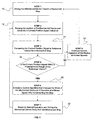
- Fig. 1 is a flow diagram depicting the operation of the soft stop control algorithm
- Fig. 2 is a flow diagram of the motor over heat control algorithm.
- While the present embodiment describes using the control algorithms described herein with an electronic throttle control actuator, it is within the scope of this invention to incorporate the control algorithms for both soft stop and motor overheat with any type of actuator.
- the control algorithms described herein can be used to protect actuators used in transmissions, gear shifts, exhaust gas recirculation systems and turbo systems. All of the above systems incorporate actuators that include both AC and DC motors and can include but certainly not be limited to both brush and brushless DC motors, servo motors, solenoids and torque motors. All of the above actuators are linked with mechanical components that are controlled by the movement of the actuator.
- Fig. 1 depicts a flow diagram of the control algorithm for providing soft stop control of the mechanical throttle control device.
- a mechanical throttle control device typically has a throttle body with a butterfly valve rotatably disposed within an orifice of the throttle body. The butterfly valve rotates with the rotation of a throttle shaft. There are generally two mechanical stops provided on the valve body which prevent the throttle shaft from rotating 360 degrees. These mechanical stops will allow the butterfly valve portion to move from a closed position where the butterfly valve completely covers the opening in the throttle body to a fully open position where the butterfly valve is moved to an approximately perpendicular plane with respect to the butterfly valve's fully closed position.
- the fully closed position has a first mechanical stop that prevents the butterfly valve from rotating past the fully closed position and a second mechanical stop which prevents the butterfly valve from rotating past the fully open position.
- One of the problems addressed by this invention is to prevent the components of the throttle valve from striking the first or second mechanical stops at a high velocity which can damage the control components. In an ETC setting it is desirable to prevent the portions of the throttle valve from forcefully contacting or striking the mechanical stops by using non-mechanical means.
- First step 10 includes driving the mechanical device toward a mechanical stop.
- the mechanical stop can be either the first stop (valve fully closed position) or a second stop (valve fully open position).
- the throttle valve is driven under normal operation and normal operating speeds.
- a second step 12 of figure 1 provides for sensing the position of the mechanical device (the throttle valve position) and converting the position to a current position signal.
- Sensors are used in conjunction with the throttle body to sense the position of the valve plate.
- Sensor types can include Hall Effect sensors, induction sensors as well as any other type of contact or non-contact sensors.
- the sensors function to convert the position of the butterfly valve plate by assigning it a signal value that is called the current position signal.
- the current position signal is transmitted to a comparator.
- the current position signal is compared to reference values.
- the comparator has a look up table with preprogrammed reference values that represent signal values indicative of the location of the mechanical stop.
- the comparator When the current position signal is compared to reference values, the comparator will carry out a fourth step 16 of the method, where the comparator determines whether the current position signal is within a predetermined range or error of the reference values for the mechanical stop. If the current position is not within the predetermined range of the reference values the system carries out a fifth step 18 where the throttle control valve will continue normal operation of the device at normal speeds and steps one through four 10, 12, 14, 16 will be repeated.
- a sixth step 20 is executed and a control algorithm is activated within a controller so that the mechanical device operates at a slower speed prior to contacting the stop.
- a seventh step 22 returns the throttle valve to normal operation and drives the throttle in a direction away from the mechanical stop. The system will reset itself and the second step 12 is carried out causing the system to begin sensing the position of the mechanical device.
- Figure 2 depicts a flow chart diagram for a control algorithm for preventing motor overheat in an electronic throttle control system.
- the first step 110 includes introducing an electric current to the motor for the driving valve between the open and closed position.
- the second step 112 includes using a sensor connected to a motor to constantly sense the amount of current flowing through the motor or position actuator.
- the sensors also perform a third step 114 of generating a range of signal values that are indicative of the current flowing through the motor at a given time.
- the range of signal values are sent to a comparator that carries out a fourth step 116 of calculating the integral value of the range of signal values generated by the sensors at step 114.
- the comparator also carries out a fifth step 118 of comparing the integral value to a limit reference value that is an integral value that represents the operational threshold of the motor.
- the limit reference value represents the amount of work that the motor can perform until the motor starts to overheat and sustain damage.
- the limit reference value and the integral value can be any value and it is also contemplated that this value can hold the value of zero.
- the limit reference value can also be set at a level that is lower than the threshold of the motor.
- the method described herein specifies that the limit reference value can take on a "cool down" limit reference value which may be used to limit the amount of current flowing through the motor for a set period of time while the motor cools off and recovers from a potential overheat situation.
- the comparator then examines and will then carry out a sixth step 120 of determining whether the integral value exceeds the limit reference value. If the integral value does not exceed the limit reference value then steps one through six 110, 112, 114, 116, 118, 120 are repeated. If the integral value exceeds the limit reference value established in the fifth step 118, then the controller will carry out a seventh step 122. During the seventh step 122 the controller will activate a control algorithm that sets the limit reference value to a lower "cool down" limit reference value. Simultaneously the controller will reduce the amount of current flowing through the motor for a period of time until the integral value drops and is equal to or below the lower "cool down" limit reference value.
- This process allows for the actuator to continue operating at a lower capacity while protecting the motor from damage that could be sustained if current is allowed to continue to exceed the threshold set by the limit reference value established in the fifth step 118.
- the limit reference value in the fifth step 118 and the lower "cool down" limit reference in the seventh step 122 as well as the integral value calculated in the fourth step 116 can be any type of value including the value of zero.
- Fig. 1 and Fig. 2 both have a second step 12, 112 respectfully, that describes the use of sensor devices that operate by sensing current flow through an actuator. It is possible to carry out both methods described herein by determining actuator position as well as motor overheat virtually based on other parameters. Using a virtual detection system would be helpful in the event that there is a system failure. For example, a system failure can only occur if a sensor failed and it was no longer possible to sense throttle plate position or the amount of voltage applied to the motor. A virtual system would act as a backup using data from other sensors to operate the controller. For instance throttle position could be determined using a motor overheat sensor, which could indicate the direction and the amount of time a current has been flowing through the motor.
- the throttle plate position could be estimated based on these parameters.
- data could be inputted from the throttle position sensor that would indicate the length of time and amount of current flowing through the system (i.e., the motor) based upon the position of the throttle.
- Both of the above described virtual systems would involve extrapolating the position of the mechanical device from the second step 12 and/or determining the amount of current flowing through a position actuator in the second step 112 using data inputted from other sources. While the above description of virtual systems specifically mention using the throttle position motor overheat sensors to generate data, it is within the scope of this invention use any sensor in the vehicle that can be used to extrapolate data for use in the methods described herein.
Landscapes
- Engineering & Computer Science (AREA)
- Human Computer Interaction (AREA)
- Manufacturing & Machinery (AREA)
- Physics & Mathematics (AREA)
- General Physics & Mathematics (AREA)
- Automation & Control Theory (AREA)
- Power Engineering (AREA)
- Control Of Throttle Valves Provided In The Intake System Or In The Exhaust System (AREA)
- Control Of Electric Motors In General (AREA)
- Safety Devices In Control Systems (AREA)
- Electrical Control Of Air Or Fuel Supplied To Internal-Combustion Engine (AREA)
Priority Applications (1)
| Application Number | Priority Date | Filing Date | Title |
|---|---|---|---|
| EP10175572A EP2256567A1 (fr) | 2004-09-09 | 2005-09-01 | Système de commande de la position d'un actionneur |
Applications Claiming Priority (2)
| Application Number | Priority Date | Filing Date | Title |
|---|---|---|---|
| US60830804P | 2004-09-09 | 2004-09-09 | |
| US11/195,907 US7064508B2 (en) | 2004-09-09 | 2005-08-03 | Actuator position control system |
Related Child Applications (1)
| Application Number | Title | Priority Date | Filing Date |
|---|---|---|---|
| EP10175572A Division-Into EP2256567A1 (fr) | 2004-09-09 | 2005-09-01 | Système de commande de la position d'un actionneur |
Publications (3)
| Publication Number | Publication Date |
|---|---|
| EP1635236A2 true EP1635236A2 (fr) | 2006-03-15 |
| EP1635236A3 EP1635236A3 (fr) | 2008-04-23 |
| EP1635236B1 EP1635236B1 (fr) | 2017-08-23 |
Family
ID=35448139
Family Applications (2)
| Application Number | Title | Priority Date | Filing Date |
|---|---|---|---|
| EP05255369.0A Expired - Lifetime EP1635236B1 (fr) | 2004-09-09 | 2005-09-01 | Méthode de protection contre la surchauffe d'un moteur |
| EP10175572A Withdrawn EP2256567A1 (fr) | 2004-09-09 | 2005-09-01 | Système de commande de la position d'un actionneur |
Family Applications After (1)
| Application Number | Title | Priority Date | Filing Date |
|---|---|---|---|
| EP10175572A Withdrawn EP2256567A1 (fr) | 2004-09-09 | 2005-09-01 | Système de commande de la position d'un actionneur |
Country Status (4)
| Country | Link |
|---|---|
| US (1) | US7064508B2 (fr) |
| EP (2) | EP1635236B1 (fr) |
| JP (1) | JP2006077768A (fr) |
| KR (1) | KR101301565B1 (fr) |
Cited By (1)
| Publication number | Priority date | Publication date | Assignee | Title |
|---|---|---|---|---|
| EP3620872B1 (fr) * | 2015-10-06 | 2021-11-03 | Belimo Holding AG | Actionneur et procédé de fonctionnement associé |
Families Citing this family (15)
| Publication number | Priority date | Publication date | Assignee | Title |
|---|---|---|---|---|
| US7191754B2 (en) * | 2002-03-06 | 2007-03-20 | Borgwarner Inc. | Position sensor apparatus and method |
| DE60309361T2 (de) * | 2002-03-06 | 2007-02-08 | Borgwarner Inc., Auburn Hills | Elektronische Drosselklappensteuerung mit berührlosem Positionsgeber |
| JP4539642B2 (ja) * | 2006-11-20 | 2010-09-08 | 株式会社デンソー | 内燃機関の吸気制御装置 |
| DE102007008384A1 (de) * | 2007-02-21 | 2008-08-28 | Robert Bosch Gmbh | Elektromotorischer Antrieb für ein Kraftfahrzeug-Stellteil sowie Ansteuerverfahren |
| US7800332B2 (en) | 2007-08-29 | 2010-09-21 | Honda Motor Co., Ltd. | Motor drive system and method for predicting position during power interruption |
| EP2274521B1 (fr) * | 2008-04-22 | 2020-06-17 | Borgwarner Inc. | Procédé pour commander un actionneur |
| CN101813209B (zh) * | 2009-02-20 | 2013-09-04 | 德昌电机(深圳)有限公司 | 采用无刷直流电机的执行阀控制模组及执行阀控制方法 |
| JP2011069336A (ja) * | 2009-09-28 | 2011-04-07 | Keihin Corp | 内燃機関の制御装置 |
| EP2621078B1 (fr) * | 2012-01-26 | 2014-08-13 | Siemens Aktiengesellschaft | Procédé et dispositif destinés au fonctionnement d'un moteur à courant continu sans balais lors du réglage d'un élément de réglage |
| JP6725975B2 (ja) * | 2015-09-30 | 2020-07-22 | 株式会社ケーヒン | 電子制御スロットル装置 |
| US10125699B2 (en) | 2016-11-03 | 2018-11-13 | Borgwarner Inc. | Method and actuator for use on an engine having a monitoring arrangement for determining a characteristic of [(and)] the actuator and system |
| US11397563B2 (en) * | 2017-07-21 | 2022-07-26 | Husky Injection Molding Systems Ltd. | Programming a protection device for a molding machine |
| US10976757B2 (en) | 2019-04-18 | 2021-04-13 | Flowserve Management Company | Control systems for valve actuators, valve actuators and related systems and methods |
| US11421619B2 (en) * | 2020-12-01 | 2022-08-23 | Garrett Transportation I Inc. | Wear monitoring for electrical actuators |
| JP2024018640A (ja) * | 2022-07-29 | 2024-02-08 | マツダ株式会社 | 車載デバイスの制御装置 |
Citations (1)
| Publication number | Priority date | Publication date | Assignee | Title |
|---|---|---|---|---|
| EP0794475A1 (fr) | 1995-09-26 | 1997-09-10 | Fanuc Ltd | Procede de commande en temps minimal base sur la tache, destine a un robot |
Family Cites Families (18)
| Publication number | Priority date | Publication date | Assignee | Title |
|---|---|---|---|---|
| JPS62119020A (ja) * | 1985-11-20 | 1987-05-30 | Fanuc Ltd | 射出成形機の計量装置 |
| JPH033692A (ja) * | 1989-05-29 | 1991-01-09 | Secoh Giken Inc | 負荷の数値制御装置 |
| JPH079127B2 (ja) * | 1989-08-17 | 1995-02-01 | ワイケイケイ株式会社 | 自動ドアの開閉制御方法 |
| US6246204B1 (en) * | 1994-06-27 | 2001-06-12 | Nikon Corporation | Electromagnetic alignment and scanning apparatus |
| JPH08221131A (ja) * | 1995-02-15 | 1996-08-30 | Yoshikatsu Naito | 位置決め装置 |
| KR0163918B1 (ko) * | 1995-07-03 | 1999-04-15 | 김광호 | 시간보상 기능을 갖는 직류 전동기 과전류 검출장치 |
| KR100275036B1 (ko) * | 1997-12-02 | 2000-12-15 | 김형벽 | 엘리베이터의 도어 폐쇄 제어 방법 |
| JP4320885B2 (ja) * | 1998-12-17 | 2009-08-26 | 日産自動車株式会社 | 電磁駆動弁の制御装置 |
| US6564332B1 (en) * | 1998-12-23 | 2003-05-13 | Intel Corporation | Method and apparatus for managing power consumption in a computer system responsive to the power delivery specifications of a power outlet |
| US6157888A (en) | 1999-02-08 | 2000-12-05 | Ford Global Technologies, Inc. | Input smoothing method and apparatus for an electronic throttle control system |
| JP2001221360A (ja) * | 1999-12-02 | 2001-08-17 | Nissan Motor Co Ltd | 電磁駆動弁の制御装置 |
| US6435169B1 (en) | 2000-03-17 | 2002-08-20 | Borgwarner Inc. | Integrated motor and controller for turbochargers, EGR valves and the like |
| US6289874B1 (en) | 2000-03-31 | 2001-09-18 | Borgwarner Inc. | Electronic throttle control |
| JP2002070588A (ja) * | 2000-09-04 | 2002-03-08 | Hitachi Ltd | 電子制御スロットル装置 |
| JP2003061374A (ja) * | 2001-08-20 | 2003-02-28 | Nidec Shibaura Corp | 電動アクチュエータの制御装置 |
| US6683429B2 (en) | 2002-04-24 | 2004-01-27 | Borgwarner Inc. | Electric positional actuator |
| JP2004032826A (ja) * | 2002-06-21 | 2004-01-29 | Meidensha Corp | モータ可変速制御における制動制御装置 |
| US6873894B2 (en) * | 2002-07-16 | 2005-03-29 | Magna Drivetrain Of America, Inc. | Method for operating an adaptive clutch in a power transfer assembly |
-
2005
- 2005-08-03 US US11/195,907 patent/US7064508B2/en not_active Expired - Lifetime
- 2005-09-01 EP EP05255369.0A patent/EP1635236B1/fr not_active Expired - Lifetime
- 2005-09-01 EP EP10175572A patent/EP2256567A1/fr not_active Withdrawn
- 2005-09-05 JP JP2005255800A patent/JP2006077768A/ja active Pending
- 2005-09-09 KR KR1020050084280A patent/KR101301565B1/ko not_active Expired - Fee Related
Patent Citations (1)
| Publication number | Priority date | Publication date | Assignee | Title |
|---|---|---|---|---|
| EP0794475A1 (fr) | 1995-09-26 | 1997-09-10 | Fanuc Ltd | Procede de commande en temps minimal base sur la tache, destine a un robot |
Cited By (1)
| Publication number | Priority date | Publication date | Assignee | Title |
|---|---|---|---|---|
| EP3620872B1 (fr) * | 2015-10-06 | 2021-11-03 | Belimo Holding AG | Actionneur et procédé de fonctionnement associé |
Also Published As
| Publication number | Publication date |
|---|---|
| US7064508B2 (en) | 2006-06-20 |
| JP2006077768A (ja) | 2006-03-23 |
| EP1635236A3 (fr) | 2008-04-23 |
| EP1635236B1 (fr) | 2017-08-23 |
| KR101301565B1 (ko) | 2013-09-04 |
| US20060049789A1 (en) | 2006-03-09 |
| EP2256567A1 (fr) | 2010-12-01 |
| KR20060051176A (ko) | 2006-05-19 |
Similar Documents
| Publication | Publication Date | Title |
|---|---|---|
| US7064508B2 (en) | Actuator position control system | |
| US11214303B2 (en) | Control device for vehicle | |
| US8733319B2 (en) | Electronic governor system and control device of the same | |
| US7603980B2 (en) | Sensor abnormality detecting method and electronic throttle control apparatus | |
| JP5575749B2 (ja) | アクチュエータの制御方法 | |
| CA2380340A1 (fr) | Dispositif de commande de moteur electrique et dispositif de commande de vehicule hybride | |
| US20200271221A1 (en) | Shift range control device | |
| JPWO2008081643A1 (ja) | Egrバルブ制御装置 | |
| EP1037370B1 (fr) | Commande d'un entrainement moteur avec remise à zéro du compteur mesurant le courant de surintensité | |
| US6291955B1 (en) | Motor drive control with low current limitation value | |
| CA2126129A1 (fr) | Capteur de vitesse redondant pour la regulation d'un moteur | |
| KR100394654B1 (ko) | 자동차용 전자 스로틀 시스템의 림프 홈 제어방법 | |
| US6539918B1 (en) | Electronic throttle servo hard stop detection system | |
| US6816772B2 (en) | Electronic throttle control system having operation monitor | |
| US20210313911A1 (en) | An actuator with an electric motor and a method of controlling the electric motor to maintain a current position | |
| JP3737106B2 (ja) | アイドリング段階における内燃機関の回転数制御のための方法および装置 | |
| JP3712956B2 (ja) | サーボモータの制御方法 | |
| EP3942208B1 (fr) | Procédé d'actionnement de soupape de commande, actionneur de chauffage, de ventilation et de climatisation et produit programme d'ordinateur | |
| US6763804B2 (en) | Electronic throttle servo overheat protection system | |
| CN108667392B (zh) | 电机控制器及其控制方法 | |
| JP2002070588A (ja) | 電子制御スロットル装置 | |
| JP4309530B2 (ja) | 摩擦付着性設定要素の制御方法および装置 | |
| Guo et al. | Analysis and Research on the Parameterization of Automotive Power Tailgate | |
| Lee et al. | The High Response and Precision Control of ETC Module without the Hall Position Sensor for Detecting Rotor Position of BLDC Motor | |
| US20200373865A1 (en) | Motor Control Device and Motor Control Method |
Legal Events
| Date | Code | Title | Description |
|---|---|---|---|
| PUAI | Public reference made under article 153(3) epc to a published international application that has entered the european phase |
Free format text: ORIGINAL CODE: 0009012 |
|
| AK | Designated contracting states |
Kind code of ref document: A2 Designated state(s): AT BE BG CH CY CZ DE DK EE ES FI FR GB GR HU IE IS IT LI LT LU LV MC NL PL PT RO SE SI SK TR |
|
| AX | Request for extension of the european patent |
Extension state: AL BA HR MK YU |
|
| RIN1 | Information on inventor provided before grant (corrected) |
Inventor name: WILSON, JOSEPH A. Inventor name: KEEFOVER, ROBERT |
|
| RIC1 | Information provided on ipc code assigned before grant |
Ipc: G05B 19/416 20060101ALI20071213BHEP Ipc: G05B 19/4062 20060101AFI20071213BHEP |
|
| PUAL | Search report despatched |
Free format text: ORIGINAL CODE: 0009013 |
|
| AK | Designated contracting states |
Kind code of ref document: A3 Designated state(s): AT BE BG CH CY CZ DE DK EE ES FI FR GB GR HU IE IS IT LI LT LU LV MC NL PL PT RO SE SI SK TR |
|
| AX | Request for extension of the european patent |
Extension state: AL BA HR MK YU |
|
| RIC1 | Information provided on ipc code assigned before grant |
Ipc: G05B 19/23 20060101ALI20080318BHEP Ipc: G05B 19/416 20060101ALI20080318BHEP Ipc: G05B 19/4062 20060101AFI20071213BHEP |
|
| 17P | Request for examination filed |
Effective date: 20080623 |
|
| 17Q | First examination report despatched |
Effective date: 20080731 |
|
| AKX | Designation fees paid |
Designated state(s): DE FR GB IT |
|
| STAA | Information on the status of an ep patent application or granted ep patent |
Free format text: STATUS: EXAMINATION IS IN PROGRESS |
|
| REG | Reference to a national code |
Ref country code: DE Ref legal event code: R079 Ref document number: 602005052576 Country of ref document: DE Free format text: PREVIOUS MAIN CLASS: G05B0019190000 Ipc: G05B0019406200 |
|
| GRAP | Despatch of communication of intention to grant a patent |
Free format text: ORIGINAL CODE: EPIDOSNIGR1 |
|
| STAA | Information on the status of an ep patent application or granted ep patent |
Free format text: STATUS: GRANT OF PATENT IS INTENDED |
|
| RIC1 | Information provided on ipc code assigned before grant |
Ipc: G05B 19/4062 20060101AFI20170428BHEP |
|
| INTG | Intention to grant announced |
Effective date: 20170515 |
|
| GRAS | Grant fee paid |
Free format text: ORIGINAL CODE: EPIDOSNIGR3 |
|
| GRAA | (expected) grant |
Free format text: ORIGINAL CODE: 0009210 |
|
| STAA | Information on the status of an ep patent application or granted ep patent |
Free format text: STATUS: THE PATENT HAS BEEN GRANTED |
|
| AK | Designated contracting states |
Kind code of ref document: B1 Designated state(s): DE FR GB IT |
|
| REG | Reference to a national code |
Ref country code: GB Ref legal event code: FG4D |
|
| REG | Reference to a national code |
Ref country code: DE Ref legal event code: R096 Ref document number: 602005052576 Country of ref document: DE |
|
| REG | Reference to a national code |
Ref country code: DE Ref legal event code: R097 Ref document number: 602005052576 Country of ref document: DE |
|
| PG25 | Lapsed in a contracting state [announced via postgrant information from national office to epo] |
Ref country code: IT Free format text: LAPSE BECAUSE OF FAILURE TO SUBMIT A TRANSLATION OF THE DESCRIPTION OR TO PAY THE FEE WITHIN THE PRESCRIBED TIME-LIMIT Effective date: 20170823 |
|
| PLBE | No opposition filed within time limit |
Free format text: ORIGINAL CODE: 0009261 |
|
| REG | Reference to a national code |
Ref country code: FR Ref legal event code: ST Effective date: 20180531 |
|
| STAA | Information on the status of an ep patent application or granted ep patent |
Free format text: STATUS: NO OPPOSITION FILED WITHIN TIME LIMIT |
|
| GBPC | Gb: european patent ceased through non-payment of renewal fee |
Effective date: 20171123 |
|
| 26N | No opposition filed |
Effective date: 20180524 |
|
| PG25 | Lapsed in a contracting state [announced via postgrant information from national office to epo] |
Ref country code: FR Free format text: LAPSE BECAUSE OF NON-PAYMENT OF DUE FEES Effective date: 20171023 |
|
| PG25 | Lapsed in a contracting state [announced via postgrant information from national office to epo] |
Ref country code: GB Free format text: LAPSE BECAUSE OF NON-PAYMENT OF DUE FEES Effective date: 20171123 |
|
| PGFP | Annual fee paid to national office [announced via postgrant information from national office to epo] |
Ref country code: DE Payment date: 20210812 Year of fee payment: 17 |
|
| REG | Reference to a national code |
Ref country code: DE Ref legal event code: R119 Ref document number: 602005052576 Country of ref document: DE |
|
| PG25 | Lapsed in a contracting state [announced via postgrant information from national office to epo] |
Ref country code: DE Free format text: LAPSE BECAUSE OF NON-PAYMENT OF DUE FEES Effective date: 20230401 |