EP1635362B1 - Hochleistungswiderstand mit Kühlmedium - Google Patents
Hochleistungswiderstand mit Kühlmedium Download PDFInfo
- Publication number
- EP1635362B1 EP1635362B1 EP05015436A EP05015436A EP1635362B1 EP 1635362 B1 EP1635362 B1 EP 1635362B1 EP 05015436 A EP05015436 A EP 05015436A EP 05015436 A EP05015436 A EP 05015436A EP 1635362 B1 EP1635362 B1 EP 1635362B1
- Authority
- EP
- European Patent Office
- Prior art keywords
- housing
- power resistor
- cooling medium
- high power
- separators
- Prior art date
- Legal status (The legal status is an assumption and is not a legal conclusion. Google has not performed a legal analysis and makes no representation as to the accuracy of the status listed.)
- Expired - Lifetime
Links
Images




Classifications
-
- H—ELECTRICITY
- H01—ELECTRIC ELEMENTS
- H01C—RESISTORS
- H01C3/00—Non-adjustable metal resistors made of wire or ribbon, e.g. coiled, woven or formed as grids
- H01C3/02—Non-adjustable metal resistors made of wire or ribbon, e.g. coiled, woven or formed as grids arranged or constructed for reducing self-induction, capacitance or variation with frequency
-
- H—ELECTRICITY
- H01—ELECTRIC ELEMENTS
- H01C—RESISTORS
- H01C1/00—Details
- H01C1/08—Cooling, heating or ventilating arrangements
-
- H—ELECTRICITY
- H01—ELECTRIC ELEMENTS
- H01C—RESISTORS
- H01C1/00—Details
- H01C1/08—Cooling, heating or ventilating arrangements
- H01C1/082—Cooling, heating or ventilating arrangements using forced fluid flow
-
- H—ELECTRICITY
- H02—GENERATION; CONVERSION OR DISTRIBUTION OF ELECTRIC POWER
- H02K—DYNAMO-ELECTRIC MACHINES
- H02K11/00—Structural association of dynamo-electric machines with electric components or with devices for shielding, monitoring or protection
- H02K11/0094—Structural association with other electrical or electronic devices
-
- H—ELECTRICITY
- H02—GENERATION; CONVERSION OR DISTRIBUTION OF ELECTRIC POWER
- H02K—DYNAMO-ELECTRIC MACHINES
- H02K7/00—Arrangements for handling mechanical energy structurally associated with dynamo-electric machines, e.g. structural association with mechanical driving motors or auxiliary dynamo-electric machines
- H02K7/10—Structural association with clutches, brakes, gears, pulleys or mechanical starters
- H02K7/106—Structural association with clutches, brakes, gears, pulleys or mechanical starters with dynamo-electric brakes
Definitions
- the invention relates to a high power resistor and a resistor unit consisting of several such high power resistors.
- High-power resistors are used in particular for braking electric motors, in particular in thyristor drives, in particular high-frequency thyristor drives, but also for many other applications in the field of control and regulation of electric drives. High-power resistors are needed in particular in automotive technology.
- Known high power resistors include a wire made of an electrically resistive material wound around a core, which core is generally capable of withstanding high temperatures.
- high power resistors consisting of a spiral wire that is not wound around a core. The wire is provided with electrical insulation. It is located in a thermally conductive material, which is surrounded by a metallic housing, which acts as a heat exchanger.
- the prior art high power resistors are particularly troublesome when the operating frequency is high, for example, higher than one kHz, and / or when it is important to maintain the waveform of the current.
- the problems arise in the prior art power resistors, in particular the fact that they have a certain capacity and / or inductance by their construction, by the shape and format of the voltage signal and / or the current signal, which may be rectangular or sinusoidal, for example, in an inadmissible manner can be affected.
- a high-performance resistor according to the preamble of claim 1 is known from US-A-3 550 058 known.
- the object of the invention is to improve a high-performance resistor.
- the high-performance resistor comprises a housing which can be traversed or flowed through by a cooling medium and in which a plurality, preferably three, sheet-like resistance elements are provided, between which separators are provided.
- the separators serve as guide devices for the cooling medium.
- the cooling medium may be liquid or gaseous.
- the cooling medium is liquid.
- the resistive elements may be connected in parallel or in series. It is particularly advantageous if the sheet-like resistance elements are arranged parallel to one another.
- the separators allow the resistance elements to be isolated from each other. A particularly simple solution is achieved if the sheet-like resistance elements are separated from one another by sheet-like separators.
- the housing made of plastic, preferably made of thermoplastic material.
- Such a housing is inexpensive to produce.
- a terminal box is provided on the housing.
- the terminal box may have electrical contacts for connecting electrical lines.
- a further advantageous embodiment is characterized by sealed connections for connecting the resistor element to the terminal box.
- the invention further relates to a resistance unit, which consists of several high-power resistors according to the invention.
- the invention provides a cooling medium-cooled, in particular liquid-cooled, high-performance resistor. It enables the realization of a resistor with high power values and in particular with a low impedance and a low induction.
- the high-performance resistor can be used with particular advantage in the braking of electric motors, in particular in high-frequency thyristor drives, but also in many other applications in the field of electric drive technology, in particular the control and regulation of electric drives. Another important field of application is automotive technology.
- the high-power resistor shown in the drawing figures comprises a housing which consists of an upper housing part 1 and a lower housing part 1.
- the housing parts 1 are molded parts made of thermoplastic material. They are glued together and form a closed, pressure-resistant, sealed housing.
- plastic material for example, Nylon 6.6 or Nylon 4.6 with 30% nylon and 40% glass filling is suitable, as it is used by default in the automotive industry, but also other plastic materials.
- the resistance elements 3 are designed in a planar shape. They run parallel to each other and at a distance from each other.
- the resistance elements 3 have a rectangular shape, wherein the rectangle is slightly smaller than the rectangle formed by the housing parts 1.
- the resistance elements 3 are separated from each other by two separators 2.
- the separators 2 are also planar. They have a rectangular shape, which is slightly larger than the rectangles of the resistance elements 3 and slightly smaller than the rectangles of the housing parts 1.
- the separators 3 are made of thermoplastic material. For the separators 2, the same materials are suitable as for the housing parts 1.
- the separators 3 may be made of the same material as the housing parts. 1
- connections 6, namely hose connections are connected to the housing parts.
- the terminals 6 are located at the ends of a longitudinal side of the housing parts 1.
- One of the terminals 6 serves as a supply line for a cooling medium, the other as a derivative of the cooling medium.
- the cooling medium is water or a water-glycol mixture or oil. Other cooling media are suitable.
- the liquid cooling medium flows through the housing 1. It cools the heated by the action of the electric current resistance elements 3.
- the parts 1 of the housing are sealingly and pressure-tightly connected to each other, so that no coolant can escape.
- the separators 2 pass the cooling medium past the resistance elements 3 through the housing 1. They bring about a uniform distribution of the cooling medium and a uniform cooling of the resistance elements 3.
- the resistance elements 3 When the resistance elements 3 are to be connected in series, they are provided with a connecting material 4, which are configured U-shaped and which are welded to a respective resistance element 3. The connecting materials 4 are then connected to each other by an electric wire (not shown in the drawing).
- a junction box 7 is provided, which is located on a narrow side of the rectangular housing 1 and whose length coincides with the length of this narrow side.
- the junction box 7 has a rectangular cross-section, its height coinciding with that of the housing 1.
- the height of the terminal box 7 can also be a multiple of the height of the housing, for example twice ( Fig. 5 ) or quadruple ( Fig. 6 ).
- connecting pins 5 In the housing 1 side facing the terminal box 7 openings are provided in the connecting pins 5 can be inserted.
- the connecting pins 5 have in their middle O-rings which are clamped between the housing 1 facing wall of the junction box 7 and a shoulder in the connecting pins 5 and which cause a seal against the housing 1.
- the connecting pins 5 also have tongues which protrude into the housing 1 and which are electrically conductively connected to one or more resistance elements 3.
- junction box 7 electrically conductive connections are present (not shown in the drawing), which connect the protruding into the terminal box 7 parts of the pins 5 with contacts 9 electrically conductive.
- the contacts 9 are provided at the ends of the junction box 7. They form sockets for it to be attached connector of the electrical leads for the resistor element.
- the junction box 7 is closed by the cover 8. By removing the cover 8, the interior of the junction box 7 is accessible.
- the junction box 7 are parts that make the necessary connection between the resistive elements, which may be connected in series or in parallel, and the contacts 9 (not shown in the drawing).
- Fig. 6 shows a resistance unit consisting of four high-power resistors 11. On the longitudinal sides of the resistance elements 11 are each four spaced, outwardly facing projections present, in which there are holes that are each aligned with each other and can be inserted through the fasteners, such as mounting screws or mounting bolts.
- thermoplastic the weight of the high-performance resistors can be significantly reduced.
- shape and structure are also better suited for many applications, especially in the automotive industry.
- a cooling medium in particular a liquid cooling medium, causes a high efficiency of the heat transfer between the one or more resistance elements and the particular liquid cooling medium.
- the resistive element may be made of a large flat strip of suitable resistance material, such as alumina, nickel-chromium or other suitable materials. It can easily be shaped to achieve the desired resistance and power level. Suitable materials are in particular Aluchrom of the type Yhf, Y and ISE, nickel chrome 80/20, 70/30 and 30/20, but also other materials. The thickness of the material depends on the desired power distribution and the desired current; it is generally 0.25 to 0.5 mm, although lower or higher values are possible. The size of the resistance elements can be up to 400mm ⁇ 250mm and in special cases even larger.
- suitable resistance material such as alumina, nickel-chromium or other suitable materials. It can easily be shaped to achieve the desired resistance and power level. Suitable materials are in particular Aluchrom of the type Yhf, Y and ISE, nickel chrome 80/20, 70/30 and 30/20, but also other materials.
- the thickness of the material depends on the desired power distribution and the desired current; it is generally 0.25 to 0.5 mm, although lower
- the material of the housing parts 1 and the separators 2 is selected according to the requirements, in particular according to the nature of the particular liquid cooling medium.
- Particularly suitable are thermally conductive plastics, in particular synthetic resins, which cause a constant and accurate electrical and thermal insulation.
- Particularly suitable are Protavic, L112-2, L135, L163 or L181, but also other materials.
Landscapes
- Engineering & Computer Science (AREA)
- Microelectronics & Electronic Packaging (AREA)
- Physics & Mathematics (AREA)
- Fluid Mechanics (AREA)
- Details Of Resistors (AREA)
- Non-Adjustable Resistors (AREA)
- Electric Propulsion And Braking For Vehicles (AREA)
- Ignition Installations For Internal Combustion Engines (AREA)
- Cooling Or The Like Of Electrical Apparatus (AREA)
- Inorganic Insulating Materials (AREA)
- Compositions Of Oxide Ceramics (AREA)
Description
- Die Erfindung betrifft einen Hochleistungswiderstand und eine Widerstandseinheit, die aus mehreren derartigen Hochleistungswiderständen besteht.
- Hochleistungswiderstände werden insbesondere zum Bremsen von Elektromotoren verwendet, insbesondere in Thyristor-Antrieben, insbesondere Hochfrequenz-Thyristor-Antrieben, aber auch für viele andere Anwendungen auf dem Gebiet der Steuerung und Regelung von elektrischen Antrieben. Hochleistungswiderstände werden insbesondere auch in der Automobiltechnik benötigt.
- Bekannte Hochleistungswiderstände umfassen einen Draht aus einem einen elektrischen Widerstand aufweisenden Material, der um einen Kern gewickelt ist, wobei der Kern im Allgemeinen hohe Temperaturen aushalten kann. Es sind auch Hochleistungswiderstände bekannt, die aus einem Spiraldraht bestehen, der nicht um einen Kern gewickelt ist. Der Draht ist mit einer elektrischen Isolierung versehen. Er befindet sich in einem wärmeleitenden Material, das von einem metallischen Gehäuse umgeben ist, das als Wärmetauscher wirkt.
- Bei den vorbekannten Hochleistungswiderständen entstehen insbesondere dann Probleme, wenn die Betriebsfrequenz hoch ist, beispielsweise höher als ein kHz, und/oder wenn es wichtig ist, die Wellenform des Stromes beizubehalten. Die Probleme entstehen bei den vorbekannten Leistungswiderständen insbesondere dadurch, daß sie kraft ihrer Konstruktion eine gewisse Kapazität und/oder Induktivität aufweisen, durch die die Form und das Format des Spannungssignals und/oder des Stromsignals, das beispielsweise rechteckig oder sinusförmig sein kann, in unzulässiger Weise beeinträchtigt werden kann.
- Ein Hochleistungswiderstand nach dem Oberbegriff des Anspruchs 1 ist aus der
US-A-3 550 058 bekannt. - Aufgabe der Erfindung ist es, einen Hochleistungswiderstand zu verbessern.
- Erfindungsgemäß wird diese Aufgabe durch die Merkmale des Anspruchs 1 gelöst. Der Hochleistungswiderstand umfaßt ein Gehäuse, das von einem Kühlmedium durchströmbar oder durchströmt ist und in dem mehrere, vorzugsweise drei, flächenförmige Widerstandselemente vorgesehen sind, zwischen denen Separatoren vorgesehen sind. Erfindungsgemäß dienen die Separatoren als Leitvorrichtungen für das Kühlmedium. Das Kühlmedium kann flüssig oder gasförmig sein. Vorzugsweise ist das Kühlmedium flüssig. Die Widerstandselemente können parallel oder in Reihe geschaltet sein. Besonders vorteilhaft ist es, wenn die flächenförmigen Widerstandselemente parallel zueinander angeordnet sind. Durch die Separatoren können die Widerstandselemente voneinander isoliert werden. Eine besonders einfache Lösung wird erreicht, wenn die flächenförmigen Widerstandselemente durch flächenförmige Separatoren voneinander getrennt werden.
- Vorteilhafte Weiterbildungen sind in den Unteransprüchen beschrieben.
- Eine vorteilhafte Weiterbildung ist dadurch gekennzeichnet, daß das Gehäuse aus Kunststoff, vorzugsweise aus thermoplastischem Kunststoff, besteht. Ein derartiges Gehäuse ist kostengünstig herstellbar.
- Vorzugsweise ist an dem Gehäuse ein Anschlußkasten vorgesehen. Der Anschlußkasten kann elektrische Kontakte zum Anschluß von elektrischen Leitungen aufweisen.
- Eine weitere vorteilhafte Weiterbildung ist durch abgedichtete Anschlüsse zur Verbindung des Widerstandselements mit dem Anschlußkasten gekennzeichnet.
- Die Erfindung betrifft ferner eine Widerstandseinheit, die aus mehreren erfindungsgemäßen Hochleistungswiderständen besteht.
- Durch die Erfindung wird ein kühlmedium-gekühlter, insbesondere flüssigkeitsgekühlter Hochleistungswiderstand geschaffen. Sie ermöglicht die Realisierung eines Widerstandes mit hohen Leistungswerten und insbesondere mit einer geringen Impedanz und einer geringen Induktion. Der Hochleistungswiderstand kann mit besonderem Vorteil beim Bremsen von elektrischen Motoren, insbesondere in Hochfrequenz-Thyristor-Antrieben, verwendet werden, aber auch in vielen anderen Anwendungen auf dem Gebiet der elektrischen Antriebstechnik, insbesondere der Steuerung und Regelung von elektrischen Antrieben. Ein weiteres bedeutsames Anwendungsfeld ist die Automobiltechnik.
- Insbesondere in Anwendungsgebieten, in denen es auf ein geringes Gewicht und/oder eine hohe Packungsdichte der elektrischen und/oder elektronischen Komponenten ankommt, insbesondere in der Automobilindustrie, wird eine möglichst hohe Leistungsdisipation angestrebt. Dies ist insbesondere bei starken Bremsvorgängen erforderlich. Zur gleichen Zeit soll der benötigte Platz gering gehalten werden. Die Erfindung ermöglicht es, diese Probleme zu lösen.
- Ausführungsbeispiele der Erfindung werden nachstehend anhand der beigefügten Zeichnung im einzelnen erläutert. In der Zeichnung zeigt
- Fig. 1
- einen Hochleistungswiderstand in einer perspektivischen Explosionsansicht,
- Fig. 2
- den Hochleistungswiderstand gemäß
Fig. 1 in einer Seitenansicht, - Fig. 3
- den Hochleistungswiderstand gemäß
Fig. 1 und2 in einer Ansicht von oben, - Fig. 4
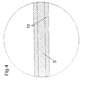
- einen Schnitt durch ein Widerstandselement des Hochleistungswiderstands gemäß
Fig. 1 bis 3 , - Fig. 5
- den Hochleistungswiderstand gemäß
Fig. 1 bis 3 in zusammengebautem Zustand in einer perspektivischen Ansicht und - Fig. 6
- eine Widerstandseinheit, die aus vier Hochleistungswiderständen gemäß
Fig. 1 bis 3 und5 besteht. - Der in den Zeichnungsfiguren dargestellte Hochleistungswiderstand umfaßt ein Gehäuse, das aus einem oberen Gehäuseteil 1 und einem unteren Gehäuseteil 1 besteht. Die Gehäuseteile 1 sind Formteile aus thermoplastischem Kunststoff. Sie sind miteinander verklebt und bilden ein geschlossenes, druckfestes, abgedichtetes Gehäuse. Als Kunststoffmaterial ist beispielsweise Nylon 6.6 oder Nylon 4.6 mit 30% Nylon und 40% Glasfüllung geeignet, wie es standardmäßig in der Automobilindustrie verwendet wird, aber auch andere Kunststoffmaterialien.
- In dem Gehäuse sind drei Widerstandselemente 3 angeordnet. Die Widerstandselemente 3 sind flächenförmig ausgestaltet. Sie verlaufen parallel zueinander und im Abstand voneinander. Die Widerstandselemente 3 weisen eine Rechteckform auf, wobei das Rechteck etwas kleiner ist als das von den Gehäuseteilen 1 gebildete Rechteck.
- Die Widerstandselemente 3 werden durch zwei Separatoren 2 voneinander getrennt. Die Separatoren 2 sind ebenfalls flächenförmig. Sie weisen eine rechteckige Form auf, die etwas größer ist als die Rechtecke der Widerstandselemente 3 und etwas kleiner als die Rechtecke der Gehäuseteile 1. Die Separatoren 3 sind aus thermoplastischem Kunststoff. Für die Separatoren 2 sind dieselben Materialien geeignet wie für die Gehäuseteile 1. Die Separatoren 3 können aus demselben Material gefertigt sein wie die Gehäuseteile 1.
- Im zusammengebauten Zustand sind mit den Gehäuseteilen 1 Anschlüsse 6, nämlich Schlauchanschlüsse, verbunden. Die Anschlüsse 6 befinden sich an den Enden einer Längsseite der Gehäuseteile 1. Einer der Anschlüsse 6 dient als Zuleitung für ein Kühlmedium, der andere als Ableitung für das Kühlmedium. Bei dem Kühlmedium handelt es sich um Wasser oder eine Wasser-Glykol-Mischung oder Öl. Auch andere Kühlmedien sind geeignet. Das flüssige Kühlmedium durchströmt das Gehäuse 1. Es kühlt dabei die sich durch die Wirkung des elektrischen Stroms erhitzenden Widerstandselemente 3. Die Teile 1 des Gehäuses sind dichtend und druckdicht miteinander verbunden, so daß kein Kühlmittel austreten kann. Die Separatoren 2 leiten das Kühlmedium an den Widerstandselementen 3 vorbei durch das Gehäuse 1. Sie bewirken eine gleichmäßige Verteilung des Kühlmediums und eine gleichmäßige Kühlung der Widerstandselemente 3.
- Wenn die Widerstandselemente 3 in Serie geschalten werden sollen, werden sie mit einem Verbindungsmaterial 4 versehen, die U-förmig ausgestaltet sind und die mit jeweils einem Widerstandselement 3 verschweißt werden. Die Verbindungsmaterialien 4 werden dann durch eine elektrische Leitung miteinander verbunden (in der Zeichnung nicht dargestellt).
- An dem Gehäuse 1 ist ein Anschlußkasten 7 vorgesehen, der sich an einer Schmalseite des rechteckigen Gehäuses 1 befindet und dessen Länge mit der Länge dieser Schmalseite übereinstimmt. Der Anschlußkasten 7 hat einen rechtekkigen Querschnitt, wobei seine Höhe mit derjenigen des Gehäuses 1 übereinstimmt. Die Höhe des Anschlußkastens 7 kann allerdings auch ein Vielfaches der Höhe des Gehäuses betragten, beispielsweise das Doppelte (
Fig. 5 ) oder das Vierfache (Fig. 6 ). - In der dem Gehäuse 1 zugewandten Seite des Anschlußkastens 7 sind Öffnungen vorgesehen, in die Verbindungsstifte 5 einsteckbar sind. Die Verbindungsstifte 5 weisen in ihrer Mitte O-Ringe auf, die zwischen der dem Gehäuse 1 zugewandten Wand des Anschlußkastens 7 und einem Absatz in den Verbindungsstiften 5 eingeklemmt sind und die eine Abdichtung gegenüber dem Gehäuse 1 bewirken. Die Verbindungsstifte 5 weisen ferner Zungen auf, die in das Gehäuse 1 hineinragen und die mit jeweils einem oder mehreren Widerstandselementen 3 elektrisch leitend verbunden sind.
- In dem Anschlußkasten 7 sind elektrisch leitende Verbindungen vorhanden (in der Zeichnung nicht dargestellt), die die in den Anschlußkasten 7 hineinragenden Teile der Anschlußstifte 5 mit Kontakten 9 elektrisch leitend verbinden. Die Kontakte 9 sind an den Enden des Anschlußkastens 7 vorgesehen. Sie bilden Buchsen für daran anzubringende Stecker der elektrischen Anschlußleitungen für das Widerstandselement. Der Anschlußkasten 7 wird durch die Abdeckung 8 geschlossen. Durch eine Entfernung der Abdeckung 8 ist das Innere des Anschlußkastens 7 zugänglich. In dem Anschlußkasten 7 sind Teile vorhanden, die die notwendige Verbindung zwischen den Widerstandselementen, die in Reihe oder parallel geschaltet sein können, und den Kontakten 9 herstellen (in der Zeichnung nicht dargestellt).
-
Fig. 6 zeigt eine Widerstandseinheit, die aus vier Hochleistungswiderständen 11 besteht. An den Längsseiten der Widerstandselemente 11 sind jeweils vier beabstandete, nach außen weisende Vorsprünge vorhanden, in denen sich Löcher befinden, die jeweils miteinander fluchten und durch die Befestigungsteile, beispielsweise Befestigungsschrauben oder Befestigungsbolzen, hindurchgesteckt werden können. - Durch die Verwendung von Kunststoff, insbesondere thermoplastischem Kunststoff, kann das Gewicht der Hochleistungswiderstände erheblich vermindert werden. Auch die Form und die Struktur ist für viele Anwendungsfälle besser geeignet, insbesondere in der Automobilindustrie. Die Verwendung eines Kühlmediums, insbesondere eines flüssigen Kühlmediums, bewirkt eine hohe Wirksamkeit des Wärmeübergangs zwischen dem oder den Widerstandselementen und dem insbesondere flüssigen Kühlmedium.
- Das Widerstandselement kann aus einem großen flachen Streifen eines geeigneten Widerstandsmaterials gefertigt sein, beispielsweise aus Aluchrom, Nickel-Chrom oder anderen geeigneten Materialien. Es kann auf einfache Weise derart geformt werden, daß der gewünschte Widerstandswert und der gewünschte Leistungswert erreicht werden. Als Material eignen sich insbesondere Aluchrom vom Typ Yhf, Y und ISE, Nickelchrom 80/20, 70/30 und 30/20, aber auch andere Materialien. Die Dicke des Materials hängt von der gewünschten Leistungsverteilung und dem gewünschten Strom ab; sie beträgt im Allgemeinen 0,25 bis 0,5mm, wobei allerdings auch geringere oder höhere Werte möglich sind. Die Größe der Widerstandselemente kann bis zu 400mm × 250mm betragen und in besonderen Fällen auch noch größer sein.
- Das Material der Gehäuseteile 1 und der Separatoren 2 wird nach den Anforderungen ausgewählt, insbesondere nach der Art des insbesondere flüssigen Kühlmediums. Besonders geeignet sind wärmeleitende Kunststoffe, insbesondere Kunstharze, die eine konstante und genaue elektrische und thermische Isolierung bewirken. Geeignet sind insbesondere Protavic, L112-2, L135, L163 oder L181, aber auch andere Materialien.
Claims (6)
- Hochleistungswiderstand mit einem Gehäuse (1), das von einem Kühlmedium durchströmbar oder durchströmt ist und in dem mehrere flächenförmige Widerstandselemente (3) vorgesehen sind, zwischen denen Separatoren (2) vorgesehen sind,
dadurch gekennzeichnet,
daß die Separatoren (2) als Leitvorrichtungen für das Kühlmedium dienen. - Hochleistungswiderstand nach Anspruch 1, dadurch gekennzeichnet, daß das Gehäuse (1) aus Kunststoff, vorzugsweise aus thermoplastischem Kunststoff, besteht.
- Hochleistungswiderstand nach einem der vorhergehenden Ansprüche, dadurch gekennzeichnet, daß an dem Gehäuse (1) Anschlüsse (6) für die Zuleitung und die Ableitung des Kühlmediums vorgesehen sind.
- Hochleistungswiderstand nach einem der vorhergehenden Ansprüche, dadurch gekennzeichnet, daß an dem Gehäuse (1) ein Anschlußkasten (7) vorgesehen ist.
- Hochleistungswiderstand nach Anspruch 4, gekennzeichnet durch abgedichtete Anschlüsse (5) zur Verbindung des Widerstandselements (3) mit dem Anschlußkasten (7).
- Widerstandseinheit, bestehend aus mehreren Hochleistungswiderständen (11) nach einem der Ansprüche 1 bis 5.
Priority Applications (1)
| Application Number | Priority Date | Filing Date | Title |
|---|---|---|---|
| PL05015436T PL1635362T3 (pl) | 2004-09-09 | 2005-07-15 | Rezystor wielkiej mocy z czynnikiem chłodzącym |
Applications Claiming Priority (1)
| Application Number | Priority Date | Filing Date | Title |
|---|---|---|---|
| DE102004048661A DE102004048661A1 (de) | 2004-09-09 | 2004-09-09 | Hochleistungswiderstand |
Publications (3)
| Publication Number | Publication Date |
|---|---|
| EP1635362A1 EP1635362A1 (de) | 2006-03-15 |
| EP1635362B1 true EP1635362B1 (de) | 2009-03-25 |
| EP1635362B8 EP1635362B8 (de) | 2009-08-19 |
Family
ID=35044567
Family Applications (1)
| Application Number | Title | Priority Date | Filing Date |
|---|---|---|---|
| EP05015436A Expired - Lifetime EP1635362B8 (de) | 2004-09-09 | 2005-07-15 | Hochleistungswiderstand mit Kühlmedium |
Country Status (9)
| Country | Link |
|---|---|
| US (1) | US7501927B2 (de) |
| EP (1) | EP1635362B8 (de) |
| JP (1) | JP4740698B2 (de) |
| KR (1) | KR101158932B1 (de) |
| CN (1) | CN1763869B (de) |
| AT (1) | ATE426905T1 (de) |
| DE (2) | DE102004048661A1 (de) |
| ES (1) | ES2321953T3 (de) |
| PL (1) | PL1635362T3 (de) |
Families Citing this family (4)
| Publication number | Priority date | Publication date | Assignee | Title |
|---|---|---|---|---|
| CN101916634B (zh) * | 2010-08-03 | 2011-09-28 | 荣信电力电子股份有限公司 | 自冷型超大功率电阻器 |
| CN105097155B (zh) * | 2015-08-21 | 2018-05-22 | 孝感华工高理电子有限公司 | 一种汽车空调调速电阻器的芯片模块部分及调速电阻器 |
| US9941036B2 (en) * | 2016-02-02 | 2018-04-10 | Raytheon Company | Modular, high density, low inductance, media cooled resistor |
| CN106683808B (zh) * | 2016-11-25 | 2019-02-01 | 航天重型工程装备有限公司 | 一种电阻箱 |
Family Cites Families (17)
| Publication number | Priority date | Publication date | Assignee | Title |
|---|---|---|---|---|
| US635719A (en) * | 1896-12-10 | 1899-10-24 | Goss Printing Press Co Ltd | Folding and delivery mechanism for printing-presses. |
| US3550058A (en) | 1968-05-29 | 1970-12-22 | Marvin A Du Bois Jr | Electrical resistor structure |
| JPS596601B2 (ja) * | 1980-02-28 | 1984-02-13 | 毅 飯岡 | 畦盛り装置 |
| JPS5772301A (en) * | 1980-10-24 | 1982-05-06 | Tokyo Shibaura Electric Co | Water-cooled resistor |
| DE3267531D1 (en) * | 1981-05-21 | 1986-01-02 | Bbc Brown Boveri & Cie | Liquid-cooled power resistor and its application |
| JPS5899801A (ja) * | 1981-12-09 | 1983-06-14 | Yanmar Agricult Equip Co Ltd | 農業機械の自動制御装置 |
| JPS61177393A (ja) * | 1985-01-31 | 1986-08-09 | Furukawa Electric Co Ltd:The | リン青銅のSn又はSn合金メツキ方法 |
| JPS61177393U (de) | 1985-04-22 | 1986-11-05 | ||
| US4716396A (en) * | 1986-07-10 | 1987-12-29 | Dale Electronics, Inc. | High power density, low corona resistor |
| US4727351A (en) * | 1987-06-23 | 1988-02-23 | E-Systems, Inc. | High power RF resistor |
| IL89384A (en) * | 1989-02-22 | 1993-01-31 | Alexander Drabkin | High-precision, high-stability resistor elements |
| DE4008422A1 (de) * | 1990-03-16 | 1991-09-19 | Asea Brown Boveri | Leistungswiderstand |
| DE9203354U1 (de) * | 1992-03-12 | 1992-04-30 | Siemens AG, 80333 München | Flüssigkeitsgekühlter Hochlastwiderstand |
| US5796584A (en) * | 1996-04-30 | 1998-08-18 | Telefonaktiebolaget Lm Ericsson | Bridge for power transistors with improved cooling |
| JP3831572B2 (ja) * | 2000-04-19 | 2006-10-11 | 三菱電機株式会社 | 水冷抵抗器 |
| CN2494022Y (zh) * | 2001-07-17 | 2002-05-29 | 刘少峰 | 大功率水冷线绕电阻器 |
| US6924726B2 (en) * | 2002-11-19 | 2005-08-02 | Abb Ab | Liquid-cooled high-power resistor |
-
2004
- 2004-09-09 DE DE102004048661A patent/DE102004048661A1/de not_active Withdrawn
-
2005
- 2005-07-15 ES ES05015436T patent/ES2321953T3/es not_active Expired - Lifetime
- 2005-07-15 EP EP05015436A patent/EP1635362B8/de not_active Expired - Lifetime
- 2005-07-15 AT AT05015436T patent/ATE426905T1/de not_active IP Right Cessation
- 2005-07-15 DE DE502005006932T patent/DE502005006932D1/de not_active Expired - Lifetime
- 2005-07-15 PL PL05015436T patent/PL1635362T3/pl unknown
- 2005-09-07 KR KR1020050083055A patent/KR101158932B1/ko not_active Expired - Fee Related
- 2005-09-07 JP JP2005259639A patent/JP4740698B2/ja not_active Expired - Fee Related
- 2005-09-09 CN CN2005100998930A patent/CN1763869B/zh not_active Expired - Fee Related
- 2005-09-09 US US11/223,442 patent/US7501927B2/en not_active Expired - Fee Related
Also Published As
| Publication number | Publication date |
|---|---|
| PL1635362T3 (pl) | 2009-10-30 |
| DE502005006932D1 (de) | 2009-05-07 |
| ATE426905T1 (de) | 2009-04-15 |
| US7501927B2 (en) | 2009-03-10 |
| EP1635362A1 (de) | 2006-03-15 |
| CN1763869A (zh) | 2006-04-26 |
| US20060158797A1 (en) | 2006-07-20 |
| KR101158932B1 (ko) | 2012-06-21 |
| DE102004048661A1 (de) | 2006-03-30 |
| CN1763869B (zh) | 2010-06-16 |
| JP2006080520A (ja) | 2006-03-23 |
| ES2321953T3 (es) | 2009-06-15 |
| JP4740698B2 (ja) | 2011-08-03 |
| KR20060051066A (ko) | 2006-05-19 |
| EP1635362B8 (de) | 2009-08-19 |
| HK1088709A1 (en) | 2006-11-10 |
Similar Documents
| Publication | Publication Date | Title |
|---|---|---|
| EP2428746B1 (de) | Wärmeübertrager | |
| EP1318694B1 (de) | Elektrische Heizvorrichtung | |
| EP2428747B1 (de) | Wärmeübertrager | |
| DE3939017C2 (de) | Induktiv beheizbare Vorrichtung | |
| DE102019133043A1 (de) | Platine und Fluidheizer | |
| DE19542162C2 (de) | Überstrombegrenzer | |
| DE102007001234A1 (de) | Halbleiterbaugruppe zum Anschluss an eine Transformatorwicklung und Transformatoranordnung | |
| DE112016001620T5 (de) | Rauschfilter | |
| WO2008083839A1 (de) | Windungselement für eine spulenwicklung und transformatoranordnung | |
| DE112007001364T5 (de) | Wärmewiderstand sowie Halbleitereinrichtung und elektrische Einrichtung mit einem derartigen Wärmewiderstand | |
| DE102013211579A1 (de) | Wärmetauschereinrichtung und Heizvorrichtung | |
| DE102013211581A1 (de) | Heizvorrichtung | |
| EP0604481B1 (de) | Flüssigkeitsgekühlter hochlastwiderstand | |
| DE1589808B2 (de) | Vorrichtung zur Materialverformung durch magnetische Kräfte | |
| DE102011007334A1 (de) | Flüssigkeitsgekühlte induktive Komponente | |
| WO2024200354A1 (de) | Elektrische kontaktierung in einem kühlbaren widerstand | |
| EP2346304B1 (de) | Wärmeübertrager | |
| EP1635362A1 (de) | Hochleistungswiderstand mit Kühlung durch ein strömendes Medium | |
| EP0560139A2 (de) | Flüssigkeitsgekühlter Hochlastwiderstand | |
| DE102020202195A1 (de) | Elektrische Heizeinrichtung | |
| DE10208153A1 (de) | Vorrichtung zum Austausch von Wärme | |
| DE102019214722A1 (de) | Modulares Kühlsystem und Kühlsystemkonfiguration | |
| EP2977996A1 (de) | Drosselspule eines Stromrichters | |
| DE10236525A1 (de) | Ventilbautelement-Satz in Zweigpaar-Konfiguration für einen elektrischen Wechselrichter | |
| DE102022112762A1 (de) | Heizvorrichtung und Verfahren zur Herstellung der Heizvorrichtung |
Legal Events
| Date | Code | Title | Description |
|---|---|---|---|
| PUAI | Public reference made under article 153(3) epc to a published international application that has entered the european phase |
Free format text: ORIGINAL CODE: 0009012 |
|
| AK | Designated contracting states |
Kind code of ref document: A1 Designated state(s): AT BE BG CH CY CZ DE DK EE ES FI FR GB GR HU IE IS IT LI LT LU LV MC NL PL PT RO SE SI SK TR |
|
| AX | Request for extension of the european patent |
Extension state: AL BA HR MK YU |
|
| 17P | Request for examination filed |
Effective date: 20060725 |
|
| 17Q | First examination report despatched |
Effective date: 20060825 |
|
| 17Q | First examination report despatched |
Effective date: 20060825 |
|
| AKX | Designation fees paid |
Designated state(s): AT BE BG CH CY CZ DE DK EE ES FI FR GB GR HU IE IS IT LI LT LU LV MC NL PL PT RO SE SI SK TR |
|
| 17Q | First examination report despatched |
Effective date: 20060825 |
|
| GRAP | Despatch of communication of intention to grant a patent |
Free format text: ORIGINAL CODE: EPIDOSNIGR1 |
|
| GRAS | Grant fee paid |
Free format text: ORIGINAL CODE: EPIDOSNIGR3 |
|
| GRAA | (expected) grant |
Free format text: ORIGINAL CODE: 0009210 |
|
| AK | Designated contracting states |
Kind code of ref document: B1 Designated state(s): AT BE BG CH CY CZ DE DK EE ES FI FR GB GR HU IE IS IT LI LT LU LV MC NL PL PT RO SE SI SK TR |
|
| REG | Reference to a national code |
Ref country code: GB Ref legal event code: FG4D Free format text: NOT ENGLISH |
|
| REG | Reference to a national code |
Ref country code: CH Ref legal event code: EP |
|
| RAP2 | Party data changed (patent owner data changed or rights of a patent transferred) |
Owner name: ELDIS EHMKI & SCHMID OHG |
|
| REG | Reference to a national code |
Ref country code: IE Ref legal event code: FG4D Free format text: LANGUAGE OF EP DOCUMENT: GERMAN |
|
| REF | Corresponds to: |
Ref document number: 502005006932 Country of ref document: DE Date of ref document: 20090507 Kind code of ref document: P |
|
| REG | Reference to a national code |
Ref country code: SE Ref legal event code: TRGR |
|
| NLT2 | Nl: modifications (of names), taken from the european patent patent bulletin |
Owner name: ELDIS EHMKI & SCHMID OHG Effective date: 20090415 |
|
| REG | Reference to a national code |
Ref country code: ES Ref legal event code: FG2A Ref document number: 2321953 Country of ref document: ES Kind code of ref document: T3 |
|
| PG25 | Lapsed in a contracting state [announced via postgrant information from national office to epo] |
Ref country code: SI Free format text: LAPSE BECAUSE OF FAILURE TO SUBMIT A TRANSLATION OF THE DESCRIPTION OR TO PAY THE FEE WITHIN THE PRESCRIBED TIME-LIMIT Effective date: 20090325 Ref country code: LT Free format text: LAPSE BECAUSE OF FAILURE TO SUBMIT A TRANSLATION OF THE DESCRIPTION OR TO PAY THE FEE WITHIN THE PRESCRIBED TIME-LIMIT Effective date: 20090325 |
|
| PG25 | Lapsed in a contracting state [announced via postgrant information from national office to epo] |
Ref country code: LV Free format text: LAPSE BECAUSE OF FAILURE TO SUBMIT A TRANSLATION OF THE DESCRIPTION OR TO PAY THE FEE WITHIN THE PRESCRIBED TIME-LIMIT Effective date: 20090325 |
|
| REG | Reference to a national code |
Ref country code: IE Ref legal event code: FD4D |
|
| PG25 | Lapsed in a contracting state [announced via postgrant information from national office to epo] |
Ref country code: CZ Free format text: LAPSE BECAUSE OF FAILURE TO SUBMIT A TRANSLATION OF THE DESCRIPTION OR TO PAY THE FEE WITHIN THE PRESCRIBED TIME-LIMIT Effective date: 20090325 Ref country code: EE Free format text: LAPSE BECAUSE OF FAILURE TO SUBMIT A TRANSLATION OF THE DESCRIPTION OR TO PAY THE FEE WITHIN THE PRESCRIBED TIME-LIMIT Effective date: 20090325 Ref country code: PT Free format text: LAPSE BECAUSE OF FAILURE TO SUBMIT A TRANSLATION OF THE DESCRIPTION OR TO PAY THE FEE WITHIN THE PRESCRIBED TIME-LIMIT Effective date: 20090901 |
|
| REG | Reference to a national code |
Ref country code: PL Ref legal event code: T3 |
|
| PG25 | Lapsed in a contracting state [announced via postgrant information from national office to epo] |
Ref country code: IS Free format text: LAPSE BECAUSE OF FAILURE TO SUBMIT A TRANSLATION OF THE DESCRIPTION OR TO PAY THE FEE WITHIN THE PRESCRIBED TIME-LIMIT Effective date: 20090725 Ref country code: SK Free format text: LAPSE BECAUSE OF FAILURE TO SUBMIT A TRANSLATION OF THE DESCRIPTION OR TO PAY THE FEE WITHIN THE PRESCRIBED TIME-LIMIT Effective date: 20090325 Ref country code: RO Free format text: LAPSE BECAUSE OF FAILURE TO SUBMIT A TRANSLATION OF THE DESCRIPTION OR TO PAY THE FEE WITHIN THE PRESCRIBED TIME-LIMIT Effective date: 20090325 |
|
| PG25 | Lapsed in a contracting state [announced via postgrant information from national office to epo] |
Ref country code: IE Free format text: LAPSE BECAUSE OF FAILURE TO SUBMIT A TRANSLATION OF THE DESCRIPTION OR TO PAY THE FEE WITHIN THE PRESCRIBED TIME-LIMIT Effective date: 20090325 Ref country code: BG Free format text: LAPSE BECAUSE OF FAILURE TO SUBMIT A TRANSLATION OF THE DESCRIPTION OR TO PAY THE FEE WITHIN THE PRESCRIBED TIME-LIMIT Effective date: 20090625 Ref country code: DK Free format text: LAPSE BECAUSE OF FAILURE TO SUBMIT A TRANSLATION OF THE DESCRIPTION OR TO PAY THE FEE WITHIN THE PRESCRIBED TIME-LIMIT Effective date: 20090325 |
|
| PLBE | No opposition filed within time limit |
Free format text: ORIGINAL CODE: 0009261 |
|
| STAA | Information on the status of an ep patent application or granted ep patent |
Free format text: STATUS: NO OPPOSITION FILED WITHIN TIME LIMIT |
|
| BERE | Be: lapsed |
Owner name: ELDIS EHMKI & SCHMID OHG Effective date: 20090731 |
|
| PG25 | Lapsed in a contracting state [announced via postgrant information from national office to epo] |
Ref country code: MC Free format text: LAPSE BECAUSE OF NON-PAYMENT OF DUE FEES Effective date: 20090731 |
|
| REG | Reference to a national code |
Ref country code: CH Ref legal event code: PL |
|
| 26N | No opposition filed |
Effective date: 20091229 |
|
| PG25 | Lapsed in a contracting state [announced via postgrant information from national office to epo] |
Ref country code: CH Free format text: LAPSE BECAUSE OF NON-PAYMENT OF DUE FEES Effective date: 20090731 Ref country code: LI Free format text: LAPSE BECAUSE OF NON-PAYMENT OF DUE FEES Effective date: 20090731 |
|
| PG25 | Lapsed in a contracting state [announced via postgrant information from national office to epo] |
Ref country code: BE Free format text: LAPSE BECAUSE OF NON-PAYMENT OF DUE FEES Effective date: 20090731 |
|
| PG25 | Lapsed in a contracting state [announced via postgrant information from national office to epo] |
Ref country code: GR Free format text: LAPSE BECAUSE OF FAILURE TO SUBMIT A TRANSLATION OF THE DESCRIPTION OR TO PAY THE FEE WITHIN THE PRESCRIBED TIME-LIMIT Effective date: 20090626 |
|
| PG25 | Lapsed in a contracting state [announced via postgrant information from national office to epo] |
Ref country code: AT Free format text: LAPSE BECAUSE OF NON-PAYMENT OF DUE FEES Effective date: 20090715 |
|
| PG25 | Lapsed in a contracting state [announced via postgrant information from national office to epo] |
Ref country code: LU Free format text: LAPSE BECAUSE OF NON-PAYMENT OF DUE FEES Effective date: 20090715 |
|
| PG25 | Lapsed in a contracting state [announced via postgrant information from national office to epo] |
Ref country code: HU Free format text: LAPSE BECAUSE OF FAILURE TO SUBMIT A TRANSLATION OF THE DESCRIPTION OR TO PAY THE FEE WITHIN THE PRESCRIBED TIME-LIMIT Effective date: 20090926 |
|
| PG25 | Lapsed in a contracting state [announced via postgrant information from national office to epo] |
Ref country code: TR Free format text: LAPSE BECAUSE OF FAILURE TO SUBMIT A TRANSLATION OF THE DESCRIPTION OR TO PAY THE FEE WITHIN THE PRESCRIBED TIME-LIMIT Effective date: 20090325 |
|
| PG25 | Lapsed in a contracting state [announced via postgrant information from national office to epo] |
Ref country code: CY Free format text: LAPSE BECAUSE OF FAILURE TO SUBMIT A TRANSLATION OF THE DESCRIPTION OR TO PAY THE FEE WITHIN THE PRESCRIBED TIME-LIMIT Effective date: 20090325 |
|
| REG | Reference to a national code |
Ref country code: DE Ref legal event code: R082 Ref document number: 502005006932 Country of ref document: DE Representative=s name: RECHTS- UND PATENTANWAELTE LORENZ SEIDLER GOSS, DE |
|
| REG | Reference to a national code |
Ref country code: DE Ref legal event code: R081 Ref document number: 502005006932 Country of ref document: DE Owner name: HIPAS AUTOMOTIVE GMBH, DE Free format text: FORMER OWNER: ELDIS EHMKI & SCHMID OHG, 85777 FAHRENZHAUSEN, DE Effective date: 20111202 Ref country code: DE Ref legal event code: R082 Ref document number: 502005006932 Country of ref document: DE Representative=s name: LORENZ SEIDLER GOSSEL RECHTSANWAELTE PATENTANW, DE Effective date: 20111202 |
|
| REG | Reference to a national code |
Ref country code: NL Ref legal event code: SD Effective date: 20130729 |
|
| REG | Reference to a national code |
Ref country code: FR Ref legal event code: TP Owner name: HIPAS AUTOMOTIVE GMBH, DE Effective date: 20130719 |
|
| REG | Reference to a national code |
Ref country code: GB Ref legal event code: 732E Free format text: REGISTERED BETWEEN 20130815 AND 20130821 |
|
| REG | Reference to a national code |
Ref country code: ES Ref legal event code: PC2A Owner name: HIPAS AUTOMOTIVE GMBH Effective date: 20130902 |
|
| REG | Reference to a national code |
Ref country code: FR Ref legal event code: PLFP Year of fee payment: 11 |
|
| PGFP | Annual fee paid to national office [announced via postgrant information from national office to epo] |
Ref country code: PL Payment date: 20150626 Year of fee payment: 11 |
|
| PGFP | Annual fee paid to national office [announced via postgrant information from national office to epo] |
Ref country code: NL Payment date: 20150723 Year of fee payment: 11 |
|
| PGFP | Annual fee paid to national office [announced via postgrant information from national office to epo] |
Ref country code: FI Payment date: 20150727 Year of fee payment: 11 Ref country code: GB Payment date: 20150723 Year of fee payment: 11 Ref country code: DE Payment date: 20150730 Year of fee payment: 11 Ref country code: ES Payment date: 20150713 Year of fee payment: 11 |
|
| PGFP | Annual fee paid to national office [announced via postgrant information from national office to epo] |
Ref country code: FR Payment date: 20150727 Year of fee payment: 11 Ref country code: SE Payment date: 20150723 Year of fee payment: 11 |
|
| PGFP | Annual fee paid to national office [announced via postgrant information from national office to epo] |
Ref country code: IT Payment date: 20150731 Year of fee payment: 11 |
|
| REG | Reference to a national code |
Ref country code: DE Ref legal event code: R119 Ref document number: 502005006932 Country of ref document: DE |
|
| REG | Reference to a national code |
Ref country code: NL Ref legal event code: MM Effective date: 20160801 |
|
| REG | Reference to a national code |
Ref country code: SE Ref legal event code: EUG |
|
| GBPC | Gb: european patent ceased through non-payment of renewal fee |
Effective date: 20160715 |
|
| PG25 | Lapsed in a contracting state [announced via postgrant information from national office to epo] |
Ref country code: SE Free format text: LAPSE BECAUSE OF NON-PAYMENT OF DUE FEES Effective date: 20160716 Ref country code: FR Free format text: LAPSE BECAUSE OF NON-PAYMENT OF DUE FEES Effective date: 20160801 Ref country code: FI Free format text: LAPSE BECAUSE OF NON-PAYMENT OF DUE FEES Effective date: 20160715 Ref country code: NL Free format text: LAPSE BECAUSE OF NON-PAYMENT OF DUE FEES Effective date: 20160801 Ref country code: DE Free format text: LAPSE BECAUSE OF NON-PAYMENT OF DUE FEES Effective date: 20170201 |
|
| REG | Reference to a national code |
Ref country code: FR Ref legal event code: ST Effective date: 20170331 |
|
| PG25 | Lapsed in a contracting state [announced via postgrant information from national office to epo] |
Ref country code: GB Free format text: LAPSE BECAUSE OF NON-PAYMENT OF DUE FEES Effective date: 20160715 |
|
| PG25 | Lapsed in a contracting state [announced via postgrant information from national office to epo] |
Ref country code: IT Free format text: LAPSE BECAUSE OF NON-PAYMENT OF DUE FEES Effective date: 20160715 |
|
| PG25 | Lapsed in a contracting state [announced via postgrant information from national office to epo] |
Ref country code: PL Free format text: LAPSE BECAUSE OF NON-PAYMENT OF DUE FEES Effective date: 20160715 |
|
| PG25 | Lapsed in a contracting state [announced via postgrant information from national office to epo] |
Ref country code: ES Free format text: LAPSE BECAUSE OF NON-PAYMENT OF DUE FEES Effective date: 20160716 |
|
| REG | Reference to a national code |
Ref country code: ES Ref legal event code: FD2A Effective date: 20181130 |