EP1635539A2 - Positionierungsstruktur, Methode zum Positionieren, Gehäuse und mobiles Endgerät - Google Patents
Positionierungsstruktur, Methode zum Positionieren, Gehäuse und mobiles Endgerät Download PDFInfo
- Publication number
- EP1635539A2 EP1635539A2 EP05107978A EP05107978A EP1635539A2 EP 1635539 A2 EP1635539 A2 EP 1635539A2 EP 05107978 A EP05107978 A EP 05107978A EP 05107978 A EP05107978 A EP 05107978A EP 1635539 A2 EP1635539 A2 EP 1635539A2
- Authority
- EP
- European Patent Office
- Prior art keywords
- positioning
- convexity
- case
- rib
- positioning convexity
- Prior art date
- Legal status (The legal status is an assumption and is not a legal conclusion. Google has not performed a legal analysis and makes no representation as to the accuracy of the status listed.)
- Withdrawn
Links
Images



Classifications
-
- H—ELECTRICITY
- H04—ELECTRIC COMMUNICATION TECHNIQUE
- H04M—TELEPHONIC COMMUNICATION
- H04M1/00—Substation equipment, e.g. for use by subscribers
- H04M1/02—Constructional features of telephone sets
- H04M1/0202—Portable telephone sets, e.g. cordless phones, mobile phones or bar type handsets
-
- H—ELECTRICITY
- H04—ELECTRIC COMMUNICATION TECHNIQUE
- H04M—TELEPHONIC COMMUNICATION
- H04M1/00—Substation equipment, e.g. for use by subscribers
- H04M1/02—Constructional features of telephone sets
- H04M1/18—Telephone sets specially adapted for use in ships, mines, or other places exposed to adverse environment
- H04M1/185—Improving the shock resistance of the housing, e.g. by increasing the rigidity
Definitions
- the present invention relates to a positioning structure and a positioning method which are applied to a mobile communication terminal or the like and, more particularly, to a case and a mobile communication terminal to which the above-described positioning structure is applied.
- FIG. 7 is a partial sectional view of a cellular phone to show a positioning structure in a conventional example and, concretely, a partial sectional view of a display section in a folding cellular phone.
- the appearance of the display section of a folding cellular phone shown in FIG. 7 is composed of top and bottom covers 101, 102 which constitute a case 100, a transparent panel 103 which is fitted into a display window 101a of the top cover 101, and a decorative panel 104 which covers the bottom cover 102.
- a display panel 105 which displays characters and the like
- a lighting unit 106 which lights the display panel 105 from the back surface thereof
- a built-in frame 107 which holds these members.
- the positioning of the built-in frame 107 is performed by fitting together a positioning concavity 107a formed in the built-in frame 107 and a positioning convexity 101b which is integrally formed on the inner surface of the top cover 101. And in the example shown in FIG. 7, the built-in frame 107 is fixed in a co-tightened manner by screws 108 which fix the top cover 101 and the bottom cover 102 together.
- the size of the positioning convexity 101b is increased, a defective appearance such as shrinkage is apt to occur in the molding of the case 100 and, therefore, it is difficult to impart sufficient strength to the positioning convexity 101b, as a result of which there is a possibility that the positioning convexity 101b is broken by such impacts as caused by a fall.
- the present invention has as its object the provision of apositioningstructure, apositioningmethod, acaseandamobile communication terminal which can resolve the problem that a positioning convexity integrally formed on the inner surface of a case is broken due to such impacts as caused by a fall by increasing the strength of the positioning convexity without causing a defective appearance during the molding of the case in spite of the integral forming of the positioning convexity on the inner surface of the case.
- the present invention provides a positioning structure which positions an incorporated member which is to be incorporated in a case with respect to the case.
- This positioning structure is constituted by a positioning concavity which is formed in the incorporated member and a positioning convexity which is integrally formed on an inner surface of the case and positions the incorporated member by fitting into the positioning concavity, the positioning convexity being formed from a rib.
- the positioning structure of the present invention is constructed in such a manner that the positioning convexity is formed from a rib which is continuous in at least two directions.
- the positioning convexity is formed in rib shapes such as a hollow quadrangle, a hollow triangle, a hollow circle, a cross, an X-shaped configuration, an L-shaped configuration, a II-shaped configuration and a C-shaped configuration, whereby the strength of the positioning convexity can be increased.
- the positioning structure of the present invention is constructed in such a manner that the positioning convexity is formed from a rib which is continuous in an endless manner.
- the positioning convexity is formed in rib shapes such as a hollow quadrangle, a hollow triangle and a hollow circle, whereby the strength of the positioning convexity can be further increased.
- the positioning structure of the present invention is constructed in such a manner that the positioning convexity is disposed in the vicinity of a screw fixing section which fixes at least the incorporated member to the case.
- the positioning structure of the present invention is constructed in such a manner that a curved surface or an inclined surface which guides the fitting into the positioning concavity is formed in a leading end portion of the rib.
- the present invention provides a positioning method for positioning an incorporated member which is to be incorporated in a case with respect to the case.
- This positioning method involves the steps of: integrally forming a positioning convexity formed from a rib on an inner surface of the case; and fitting the positioning convexity into a positioning concavity which is formed in the incorporated member, thereby positioning the incorporated member.
- the positioning convexity is formed from a rib which is continuous in at least tow directions.
- the positioning convexity is formed in rib shapes such as a hollow quadrangle, a hollow triangle, a hollow circle, a cross, an X-shaped configuration, an L-shaped configuration, a ⁇ -shaped configuration and a C-shaped configuration, whereby the strength of the positioning convexity can be increased.
- the positioning convexity is formed from a rib which is continuous in an endless manner.
- the positioning convexity is formed in rib shapes such as a hollow quadrangle, a hollow triangle and a hollow circle, whereby the strength of the positioning convexity can be further increased.
- the positioning convexity is disposed in the vicinity of a screw fixing section which fixes at least the incorporated member to the case.
- a curved surface or an inclined surface which guides the fitting into the positioning concavity is formed in a leading end portion of the rib.
- the present invention provides a case in which an incorporated member is to be incorporated, and this case integrally contains a positioning convexity which positions the incorporated member by fitting into a positioning concavity which is formed in the incorporated member.
- the positioning convexity is formed from a rib.
- the case of the present invention is constructed in such a manner that the positioning convexity is formed from a rib which is continuous in at least two directions.
- the positioning convexity is formed in rib shapes such as a hollow quadrangle, a hollow triangle, a hollow circle, a cross, an X-shaped configuration, an L-shaped configuration, a ⁇ -shaped configuration and a C-shaped configuration, whereby the strength of the positioning convexity can be increased.
- the case of the present invention is constructed in such a manner that the positioning convexity is formed from a rib which is continuous in an endless manner.
- the positioning convexity is formed in rib shapes such as a hollow quadrangle, a hollow triangle and a hollow circle, whereby the strength of the positioning convexity can be further increased.
- the case of the present invention is constructed in such a manner that the positioning convexity is disposed in the vicinity of a screw fixing section which fixes at least the incorporated member to the case.
- the case of the present invention is constructed in such a manner that a curved surface or an inclined surface which guides the fitting into the positioning concavity is formed in a leading end portion of the rib.
- the present invention provides a mobile communication terminal having a case in which a built-in frame is to be incorporated.
- This mobile communication terminal is constituted by a positioning concavity which is formed in the built-in frame and a positioning convexity which is integrally formed on an inner surface of the case and positions the built-in frame by fitting into the positioning concavity.
- the positioning convexity is formed from a rib.
- the mobile communication terminal of the present invention is constructed in such a manner that the positioning convexity is formed from a rib which is continuous in at least two directions.
- the positioning convexity is formed in rib shapes such as a hollow quadrangle, a hollow triangle, a hollow circle, a cross, an X-shaped configuration, an L-shaped configuration, a II-shaped configuration and a C-shaped configuration, whereby the strength of the positioning convexity can be increased.
- the mobile communication terminal of the present invention is constructed in such a manner that the positioning convexity is formed from a rib which is continuous in an endless manner.
- the positioning convexity is formed in rib shapes such as a hollow quadrangle, a hollow triangle and a hollow circle, whereby the strength of the positioning convexity can be further increased.
- the mobile communication terminal of the present invention is constructed in such a manner that the positioning convexity is disposed in the vicinity of a screw fixing section which fixes at least the built-in frame to the case.
- the mobile communication terminal of the present invention is constructed in such a manner that a curved surface or an inclined surface which guides the fitting into the positioning concavity is formed in a leading end portion of the rib.
- the present invention it is possible to increase the strength of a positioning convexity integrally formed on the inner surface of a case without causing a defective appearance in spite of the integral forming of the positioning convexity on the inner surface of the case. As a result, it is possible to prevent the breakage of the positioning convexity due to such impacts as caused by a fall by imparting strength high enough to withstand stress concentration to the positioning convexity.
- a description will be given of a cellular phone (a mobile communication terminal) to which the positioning structure (positioning method) according to an embodiment of the present invention is applied with reference to FIG. 1 to FIGS. 6A to 6H.
- FIG. 1 is a perspective view of a cellular phone
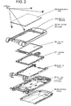
- FIG. 2 is an exploded perspective view of a display section
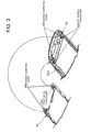
- FIG. 3 is a partial exploded perspective view of a top cover and a built-in frame
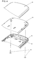
- FIG. 4 is a partial exploded perspective view of a display section
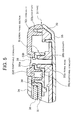
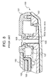
- FIG. 5 is a sectional view of a display section taken along the line A-A of FIG. 1
- FIGS. 6A to 6H are each an explanatory diagram to show various kinds of embodiments of a positioning convexity.
- the cellular phone As shown in FIG. 1, the cellular phone according to this embodiment is constructed by foldably connecting an operating section (a main body) 20 and a display section 30 together via a hinge section 10.
- the appearance of the display section 30 is constituted by top and bottom covers 32, 33 which constitute the case 31, a transparent panel 34 which is fitted in a display window 32a, and a decorative panel 35 which covers the bottom cover 33.
- a display panel 36 which displays characters and the like
- a lighting unit 37 which lights the display panel 36 from the back surface thereof
- a built-in frame 38 which holds these members.
- each of the screw fixing sections B is constituted by a screw insertion hole 32b which are formed in the top cover 32, a screw insertion hole 32a which are formed in the built-in frame 38, a fixing boss 33a which are formed in the bottom cover 33, and a screw 39. That is, the screws 39 inserted into the screw insertion holes 32b, 38a of the top cover 32 and the built-in frame 38 are screwed into the fixing bosses 33a of the bottom cover 33, whereby the top cover 32 and the bottom cover 33 are fixed together and, at the same time, the built-in frame 38 is fixed in a co-tightened manner between the top cover 32 and the bottom cover 33.
- the built-in frame 38 is first incorporated in the top cover 32, the bottom cover 33 is then fitted, and finally the screws 39 are tightened.
- the positioning of the top cover 32 and the bottom cover 33 is performed by fitting together a concavity 32c, which is integrally formed on the inner surface of an outer end portion of the top cover 32, and a convexity 33b, which is integrally formed on the inner surface of an outer end portion of the bottom cover 33.
- the positioning of the bottom cover 33 and the built-in frame 38 is performed by fitting together the fixing boss 33a of the bottom cover 33 and a downward concavity 38b, which is integrally formed in the built-in frame 38.
- the positioning of the top cover 32 and the built-in frame 38 is performed by fitting together a positioning convexity 32d, which is integrally formed on the inner surface of the top cover 32, and an upward concavity 38c, which is integrally formed in the built-in frame 38.
- the present invention is characterized by the shape and disposition of the positioning convexity 32d, and hereinafter the positioning convexity 32d will be described in detail.
- the positioning convexity 32d is formed in the shape of a rib having continuity in a prescribed direction, and not in the form of a solid pin.
- the positioning convexity 32d is formed in the shape of, for example, a hollow box (a hollow quadrangle) as shown in FIG. 6A.
- a hollow box a hollow quadrangle
- the positioning convexity 32d is formed in such a shape, it is possible to increase the strength of the positioning convexity 32d while suppressing the occurrence of a defective appearance such as shrinkage in the molding of the top cover 32. As a result, it becomes possible to prevent the breakage of the positioning convexity 32d due to impacts as caused by a fall by imparting strength high enough to withstand stress concentration to the positioning convexity 32d.
- the positioning convexity 32d be formed from a rib which is continuous in at least two directions. Shapes which may be enumerated are, for example, a hollow quadrangle shown in FIG. 6A, a hollow triangle shown in FIG. 6B, a hollow circle shown in FIG. 6C, a cross (an X-shaped configuration) shown in FIG. 6D, an L-shaped configuration shown in FIG. 6E, a ⁇ -shaped configuration shown in FIG. 6F, a C-shaped configuration shown in FIG. 6G, and a combination of L-shaped configurations shown in FIG. 6H.
- a large geometrical moment of inertia is obtained and the strength of the positioning convexity 32d can be increased.
- the positioning convexity 32d be formed from a rib which is continuous in an endless manner. Shapes which may be enumerated are, for example, the hollow quadrangle shown in FIG. 6A, the hollow triangle shown in FIG. 6B, and the hollow circle shown in FIG. 6C. When the section of the positioning convexity 32d has such shapes, the geometrical moment of inertia is further increased and the strength of the positioning convexity 32d can be increased.
- a curved surface or an inclined surface (chamfer) which guides the fitting into the positioning concavity 38c be formed in a leading end portion of the rib. This facilitates fitting together the positioning concavity 38c and the positioning convexity 32d and can improve the assemblability of the display section 30.
- the shape of the positioning concavity 38c is not especially limited so long as the shape permits fitting onto the positioning convexity 32d.
- the shape of the positioning concavity 38c may be such that the shape fits along the whole outside shape of the positioning convexity 32d as shown in FIGS. 6A to 6C or fits partially along the outside shape of the positioning convexity 32d as shown in FIGS. 6D to 6H.
- the positioning convexity 32d be disposed in the vicinity of the screw fixing section B.
- the positioning convexity 32d By disposing the positioning convexity 32d like this, in the vent of the deformation of the top cover 32 and the built-in frame 38 due to such impacts as caused by a fall, stress concentration on the positioning convexity 32d is lessened and the breakage of the positioning convexity 32d can be prevented.
- the screw insertion hole 32b of the top cover 32 and the screw insertion hole 38a of the built-in frame 38 can be positioned with good accuracy and, therefore, it is possible to resolve the problem that the screw 39 becomes slant during tightening, resulting in incomplete fastening and the problem that the tightening force of the screw 39 works on the positioning convexity 32d, thereby breaking the positioning convexity 32d.
- the cellular phone of this embodiment constructed as described above, in performing the positioning of the top cover 32 and the built-in frame 38 by fitting together the positioning concavity 38c, which is formed in the built-in frame 38, and the positioning convexity 32d, which is integrally formed on the inner surface of the top cover 32, because of the formation of the positioning convexity 32d from a rib, it becomes possible to increase the strength of the positioning convexity 32d without causing a defective appearance in the top cover 32. As a result of this, it is possible to prevent the breakage of the positioning convexity 32d due to a fall and the like by imparting strength high enough to withstand stress concentration to the positioning convexity 32d.
- the strength of the positioning convexity 32d can be increased by adopting a hollow quadrangle, a hollow triangle, a hollow circle, across, an X-shaped configuration, an L- shaped configuration , a II- shaped configuration and a C-shaped configuration, etc. as the sectional shape of the positioning convexity 32d.
- the strength of the positioning convexity 32d can be further increased by adopting a hollow quadrangle, a hollow triangle, a hollow circle, etc. as the sectional shape of the positioning convexity 32d.
- the positioning convexity 32d When the positioning convexity 32d is disposed in the vicinity of the screw fixing section B which fixes at least the built-in frame 38 to the top cover 32, stress concentration on the positioning convexity 32d can be lessenedwhen the positioning convexity 32d is subjected to such impacts as caused by a fall.
- the screw insertion holes 32b, 38a of the top cover 32 and the built-in frame 38 can be positioned with good accuracy, it is also possible to resolve the problem that during tightening, the screw 39 becomes slant and the tightening force of the screw 39 works on the positioning convexity 32d, with the result that the positioning convexity 32d is broken.
- the positioning convexity is formed on the top cover and the fixing boss is formed in the bottom cover, the positioning convexity and the fixing boss may be formed in the same cover.
- the positioning convexity is disposed in the vicinity of the inner_side of the screw fixing section
- the positioning convexity may be disposed in the vicinity of the right and left of the screw fixing section or in the vicinity of the outer side thereof.
- the built-in frame is fixed in a co-tightened manner between the top and bottom covers
- the built-in frame may be screw-fixed to either of the top and bottom covers and the positioning convexity can be disposed in the vicinity of a screw fixing section.
- the positioning structure (positioning method) of the present invention is useful also in mobile communication terminals other than a cellular phone and devices other than a mobile communication terminal.
- the present invention can be applied to equipment which performs the positioning of the case and the incorporated member.
- the present invention is also useful, in particular, in mobile communication terminals which may be subjected to such impacts as caused by a fall.
Landscapes
- Engineering & Computer Science (AREA)
- Signal Processing (AREA)
- Casings For Electric Apparatus (AREA)
- Telephone Set Structure (AREA)
Applications Claiming Priority (1)
| Application Number | Priority Date | Filing Date | Title |
|---|---|---|---|
| JP2004267299A JP2006086220A (ja) | 2004-09-14 | 2004-09-14 | 位置決め構造、位置決め方法、筐体、携帯通信端末 |
Publications (2)
| Publication Number | Publication Date |
|---|---|
| EP1635539A2 true EP1635539A2 (de) | 2006-03-15 |
| EP1635539A3 EP1635539A3 (de) | 2007-10-24 |
Family
ID=35428184
Family Applications (1)
| Application Number | Title | Priority Date | Filing Date |
|---|---|---|---|
| EP05107978A Withdrawn EP1635539A3 (de) | 2004-09-14 | 2005-08-31 | Positionierungsstruktur, Methode zum Positionieren, Gehäuse und mobiles Endgerät |
Country Status (4)
| Country | Link |
|---|---|
| US (1) | US7742791B2 (de) |
| EP (1) | EP1635539A3 (de) |
| JP (1) | JP2006086220A (de) |
| CN (1) | CN1750552B (de) |
Families Citing this family (16)
| Publication number | Priority date | Publication date | Assignee | Title |
|---|---|---|---|---|
| JP2008019993A (ja) * | 2006-07-13 | 2008-01-31 | Seiko Epson Corp | 接合構造、筐体及び電子機器 |
| JP2008191380A (ja) * | 2007-02-05 | 2008-08-21 | Nec Corp | 部材、表示部構造及び携帯端末装置 |
| JP5057085B2 (ja) * | 2008-05-30 | 2012-10-24 | Necカシオモバイルコミュニケーションズ株式会社 | 筐体構造、及び電子機器 |
| KR20100084325A (ko) * | 2009-01-16 | 2010-07-26 | 삼성전자주식회사 | 팝업 키패드 구조의 슬라이드 휴대폰 |
| TW201101963A (en) * | 2009-06-23 | 2011-01-01 | Hon Hai Prec Ind Co Ltd | Electronic device |
| JP2011117853A (ja) * | 2009-12-04 | 2011-06-16 | Denso Corp | 電流検出装置 |
| JP2012048128A (ja) * | 2010-08-30 | 2012-03-08 | Panasonic Corp | 電子機器 |
| JP5488448B2 (ja) * | 2010-12-22 | 2014-05-14 | カシオ計算機株式会社 | 携帯機器 |
| JP5686245B2 (ja) * | 2010-12-27 | 2015-03-18 | カシオ計算機株式会社 | 携帯機器 |
| WO2012127584A1 (ja) * | 2011-03-18 | 2012-09-27 | 富士通株式会社 | 携帯端末 |
| WO2013097952A1 (en) * | 2011-12-30 | 2013-07-04 | Sony Mobile Communications Ab | Corner improvement in window carrier for crack window |
| JP5556848B2 (ja) * | 2012-05-10 | 2014-07-23 | 日本電気株式会社 | 筐体構造、及び電子機器 |
| CN202918491U (zh) * | 2012-10-29 | 2013-05-01 | 瑞声光电科技(常州)有限公司 | 扬声器箱 |
| WO2014122699A1 (ja) | 2013-02-05 | 2014-08-14 | パナソニック株式会社 | 電子機器 |
| JP6512488B2 (ja) * | 2016-09-16 | 2019-05-15 | カシオ計算機株式会社 | 携帯機器 |
| CN107509339B (zh) * | 2017-09-22 | 2024-02-23 | 深圳传音制造有限公司 | 抗跌落壳体及电子产品 |
Family Cites Families (12)
| Publication number | Priority date | Publication date | Assignee | Title |
|---|---|---|---|---|
| JPS59169082A (ja) | 1983-03-16 | 1984-09-22 | Matsushita Electric Works Ltd | 充電器 |
| JPS6161878A (ja) | 1984-09-04 | 1986-03-29 | Nec Corp | スライド軸の固定構造 |
| JPH04344112A (ja) | 1991-05-20 | 1992-11-30 | Toshiba Lighting & Technol Corp | プレート |
| IT1263890B (it) * | 1993-02-11 | 1996-09-05 | Contenitore per apparecchiature elettriche o elettroniche | |
| JPH09321463A (ja) | 1996-05-24 | 1997-12-12 | Kokusai Electric Co Ltd | 電子機器の筐体構造 |
| JPH10260637A (ja) | 1997-03-19 | 1998-09-29 | Fujitsu General Ltd | 平面表示装置 |
| JPH11331333A (ja) * | 1998-05-14 | 1999-11-30 | Nec Saitama Ltd | 携帯電話機のプリント基板の実装構造 |
| JP2000223858A (ja) | 1999-02-03 | 2000-08-11 | Casio Comput Co Ltd | 小型電子機器 |
| US6678536B2 (en) * | 2000-12-07 | 2004-01-13 | Mark Wendell Fletcher | Wireless microphone |
| TW534574U (en) * | 2002-09-18 | 2003-05-21 | Benq Corp | House assembly of portable electronic device |
| TW557090U (en) * | 2003-01-29 | 2003-10-01 | Hon Hai Prec Ind Co Ltd | Portable electronic device and fastener mudule of printed circuit board tehrfor |
| US6876543B2 (en) * | 2003-03-07 | 2005-04-05 | Motorola, Inc. | Housing for a communication device and method assembling the same |
-
2004
- 2004-09-14 JP JP2004267299A patent/JP2006086220A/ja active Pending
-
2005
- 2005-08-31 EP EP05107978A patent/EP1635539A3/de not_active Withdrawn
- 2005-09-05 CN CN2005100986115A patent/CN1750552B/zh not_active Expired - Fee Related
- 2005-09-08 US US11/220,520 patent/US7742791B2/en not_active Expired - Fee Related
Also Published As
| Publication number | Publication date |
|---|---|
| JP2006086220A (ja) | 2006-03-30 |
| CN1750552B (zh) | 2010-05-26 |
| EP1635539A3 (de) | 2007-10-24 |
| US7742791B2 (en) | 2010-06-22 |
| US20060058078A1 (en) | 2006-03-16 |
| CN1750552A (zh) | 2006-03-22 |
Similar Documents
| Publication | Publication Date | Title |
|---|---|---|
| US7742791B2 (en) | Positioning structure, positioning method, case and mobile communication terminal | |
| KR100429427B1 (ko) | 디스플레이 장치와 정보 단말 기기 | |
| EP2015132A1 (de) | Tragbare elektronische Vorrichtung | |
| JP2001021869A (ja) | 液晶表示素子組立体 | |
| US20030046849A1 (en) | Carrier frame having in-frame elastic constraint structure | |
| US6937297B2 (en) | Liquid display device having a plurality of fixing pieces on corners of its panel module | |
| US6639635B2 (en) | Liquid crystal display device | |
| US20070165152A1 (en) | Liquid crystal display device | |
| US6426784B1 (en) | Liquid crystal display and method for assembling the same | |
| JP4428050B2 (ja) | 表示パネルの収納保持構造 | |
| EP1510853B9 (de) | Verfahren zur Montage eines Flüssigkristallanzeigemoduls | |
| KR100381084B1 (ko) | 플랫 패널 디스플레이 모듈과 그것을 구비하는 표시 유니트 | |
| JP2004240018A (ja) | ディスプレイ位置決め機構 | |
| JP5057085B2 (ja) | 筐体構造、及び電子機器 | |
| KR20000009873A (ko) | 엘시디 모듈 및 이를 이용한 디스플레이 장치 | |
| KR200359917Y1 (ko) | 이동통신 단말기용 메인 액정화면 보호장치 | |
| JP2006195224A (ja) | 液晶テレビジョンおよび液晶表示装置 | |
| KR100541201B1 (ko) | 액정표시모듈을 사용한 정보처리장치 및 액정표시모듈 실장방법 | |
| JP3199676B2 (ja) | 透光性プレートの取付構造 | |
| KR100442251B1 (ko) | Lcd 모니터의 프레임 | |
| US7959318B2 (en) | Backlight module | |
| JP4158172B2 (ja) | 液晶モジュールの保持装置 | |
| KR20030000305A (ko) | 몰드프레임에 체결된 바텀 섀시의 이탈 방지 구조 | |
| KR20040097572A (ko) | 휴대용 단말기의 엘시디 보호 장치 | |
| JP2007271894A (ja) | 表示パネルの保持構造及びそれを備えた電子機器 |
Legal Events
| Date | Code | Title | Description |
|---|---|---|---|
| PUAI | Public reference made under article 153(3) epc to a published international application that has entered the european phase |
Free format text: ORIGINAL CODE: 0009012 |
|
| AK | Designated contracting states |
Kind code of ref document: A2 Designated state(s): AT BE BG CH CY CZ DE DK EE ES FI FR GB GR HU IE IS IT LI LT LU LV MC NL PL PT RO SE SI SK TR |
|
| AX | Request for extension of the european patent |
Extension state: AL BA HR MK YU |
|
| PUAL | Search report despatched |
Free format text: ORIGINAL CODE: 0009013 |
|
| AK | Designated contracting states |
Kind code of ref document: A3 Designated state(s): AT BE BG CH CY CZ DE DK EE ES FI FR GB GR HU IE IS IT LI LT LU LV MC NL PL PT RO SE SI SK TR |
|
| AX | Request for extension of the european patent |
Extension state: AL BA HR MK YU |
|
| RIC1 | Information provided on ipc code assigned before grant |
Ipc: H01R 13/00 20060101ALI20070914BHEP Ipc: H04M 1/02 20060101AFI20051207BHEP |
|
| 17P | Request for examination filed |
Effective date: 20080220 |
|
| AKX | Designation fees paid |
Designated state(s): DE FR GB IT |
|
| RAP1 | Party data changed (applicant data changed or rights of an application transferred) |
Owner name: WARREN & LEWIS INVESTMENT CORPORATION |
|
| 17Q | First examination report despatched |
Effective date: 20130212 |
|
| STAA | Information on the status of an ep patent application or granted ep patent |
Free format text: STATUS: THE APPLICATION IS DEEMED TO BE WITHDRAWN |
|
| 18D | Application deemed to be withdrawn |
Effective date: 20140301 |