EP1635579A2 - Kodierungsverfahren und Wavelettransformationsvorrichtung - Google Patents
Kodierungsverfahren und Wavelettransformationsvorrichtung Download PDFInfo
- Publication number
- EP1635579A2 EP1635579A2 EP05025623A EP05025623A EP1635579A2 EP 1635579 A2 EP1635579 A2 EP 1635579A2 EP 05025623 A EP05025623 A EP 05025623A EP 05025623 A EP05025623 A EP 05025623A EP 1635579 A2 EP1635579 A2 EP 1635579A2
- Authority
- EP
- European Patent Office
- Prior art keywords
- data
- coefficient
- storage means
- stored
- code
- Prior art date
- Legal status (The legal status is an assumption and is not a legal conclusion. Google has not performed a legal analysis and makes no representation as to the accuracy of the status listed.)
- Withdrawn
Links
Images


















Classifications
-
- G—PHYSICS
- G06—COMPUTING OR CALCULATING; COUNTING
- G06F—ELECTRIC DIGITAL DATA PROCESSING
- G06F17/00—Digital computing or data processing equipment or methods, specially adapted for specific functions
- G06F17/10—Complex mathematical operations
- G06F17/14—Fourier, Walsh or analogous domain transformations, e.g. Laplace, Hilbert, Karhunen-Loeve, transforms
-
- H—ELECTRICITY
- H04—ELECTRIC COMMUNICATION TECHNIQUE
- H04N—PICTORIAL COMMUNICATION, e.g. TELEVISION
- H04N19/00—Methods or arrangements for coding, decoding, compressing or decompressing digital video signals
- H04N19/60—Methods or arrangements for coding, decoding, compressing or decompressing digital video signals using transform coding
- H04N19/63—Methods or arrangements for coding, decoding, compressing or decompressing digital video signals using transform coding using sub-band based transform, e.g. wavelets
- H04N19/635—Methods or arrangements for coding, decoding, compressing or decompressing digital video signals using transform coding using sub-band based transform, e.g. wavelets characterised by filter definition or implementation details
-
- H—ELECTRICITY
- H04—ELECTRIC COMMUNICATION TECHNIQUE
- H04N—PICTORIAL COMMUNICATION, e.g. TELEVISION
- H04N1/00—Scanning, transmission or reproduction of documents or the like, e.g. facsimile transmission; Details thereof
- H04N1/46—Colour picture communication systems
- H04N1/64—Systems for the transmission or the storage of the colour picture signal; Details therefor, e.g. coding or decoding means therefor
-
- H—ELECTRICITY
- H04—ELECTRIC COMMUNICATION TECHNIQUE
- H04N—PICTORIAL COMMUNICATION, e.g. TELEVISION
- H04N19/00—Methods or arrangements for coding, decoding, compressing or decompressing digital video signals
- H04N19/10—Methods or arrangements for coding, decoding, compressing or decompressing digital video signals using adaptive coding
- H04N19/102—Methods or arrangements for coding, decoding, compressing or decompressing digital video signals using adaptive coding characterised by the element, parameter or selection affected or controlled by the adaptive coding
- H04N19/12—Selection from among a plurality of transforms or standards, e.g. selection between discrete cosine transform [DCT] and sub-band transform or selection between H.263 and H.264
-
- H—ELECTRICITY
- H04—ELECTRIC COMMUNICATION TECHNIQUE
- H04N—PICTORIAL COMMUNICATION, e.g. TELEVISION
- H04N19/00—Methods or arrangements for coding, decoding, compressing or decompressing digital video signals
- H04N19/10—Methods or arrangements for coding, decoding, compressing or decompressing digital video signals using adaptive coding
- H04N19/102—Methods or arrangements for coding, decoding, compressing or decompressing digital video signals using adaptive coding characterised by the element, parameter or selection affected or controlled by the adaptive coding
- H04N19/129—Scanning of coding units, e.g. zig-zag scan of transform coefficients or flexible macroblock ordering [FMO]
-
- H—ELECTRICITY
- H04—ELECTRIC COMMUNICATION TECHNIQUE
- H04N—PICTORIAL COMMUNICATION, e.g. TELEVISION
- H04N19/00—Methods or arrangements for coding, decoding, compressing or decompressing digital video signals
- H04N19/10—Methods or arrangements for coding, decoding, compressing or decompressing digital video signals using adaptive coding
- H04N19/102—Methods or arrangements for coding, decoding, compressing or decompressing digital video signals using adaptive coding characterised by the element, parameter or selection affected or controlled by the adaptive coding
- H04N19/132—Sampling, masking or truncation of coding units, e.g. adaptive resampling, frame skipping, frame interpolation or high-frequency transform coefficient masking
-
- H—ELECTRICITY
- H04—ELECTRIC COMMUNICATION TECHNIQUE
- H04N—PICTORIAL COMMUNICATION, e.g. TELEVISION
- H04N19/00—Methods or arrangements for coding, decoding, compressing or decompressing digital video signals
- H04N19/10—Methods or arrangements for coding, decoding, compressing or decompressing digital video signals using adaptive coding
- H04N19/134—Methods or arrangements for coding, decoding, compressing or decompressing digital video signals using adaptive coding characterised by the element, parameter or criterion affecting or controlling the adaptive coding
- H04N19/136—Incoming video signal characteristics or properties
- H04N19/14—Coding unit complexity, e.g. amount of activity or edge presence estimation
-
- H—ELECTRICITY
- H04—ELECTRIC COMMUNICATION TECHNIQUE
- H04N—PICTORIAL COMMUNICATION, e.g. TELEVISION
- H04N19/00—Methods or arrangements for coding, decoding, compressing or decompressing digital video signals
- H04N19/10—Methods or arrangements for coding, decoding, compressing or decompressing digital video signals using adaptive coding
- H04N19/134—Methods or arrangements for coding, decoding, compressing or decompressing digital video signals using adaptive coding characterised by the element, parameter or criterion affecting or controlling the adaptive coding
- H04N19/146—Data rate or code amount at the encoder output
- H04N19/149—Data rate or code amount at the encoder output by estimating the code amount by means of a model, e.g. mathematical model or statistical model
-
- H—ELECTRICITY
- H04—ELECTRIC COMMUNICATION TECHNIQUE
- H04N—PICTORIAL COMMUNICATION, e.g. TELEVISION
- H04N19/00—Methods or arrangements for coding, decoding, compressing or decompressing digital video signals
- H04N19/10—Methods or arrangements for coding, decoding, compressing or decompressing digital video signals using adaptive coding
- H04N19/134—Methods or arrangements for coding, decoding, compressing or decompressing digital video signals using adaptive coding characterised by the element, parameter or criterion affecting or controlling the adaptive coding
- H04N19/146—Data rate or code amount at the encoder output
- H04N19/15—Data rate or code amount at the encoder output by monitoring actual compressed data size at the memory before deciding storage at the transmission buffer
-
- H—ELECTRICITY
- H04—ELECTRIC COMMUNICATION TECHNIQUE
- H04N—PICTORIAL COMMUNICATION, e.g. TELEVISION
- H04N19/00—Methods or arrangements for coding, decoding, compressing or decompressing digital video signals
- H04N19/10—Methods or arrangements for coding, decoding, compressing or decompressing digital video signals using adaptive coding
- H04N19/134—Methods or arrangements for coding, decoding, compressing or decompressing digital video signals using adaptive coding characterised by the element, parameter or criterion affecting or controlling the adaptive coding
- H04N19/156—Availability of hardware or computational resources, e.g. encoding based on power-saving criteria
-
- H—ELECTRICITY
- H04—ELECTRIC COMMUNICATION TECHNIQUE
- H04N—PICTORIAL COMMUNICATION, e.g. TELEVISION
- H04N19/00—Methods or arrangements for coding, decoding, compressing or decompressing digital video signals
- H04N19/10—Methods or arrangements for coding, decoding, compressing or decompressing digital video signals using adaptive coding
- H04N19/169—Methods or arrangements for coding, decoding, compressing or decompressing digital video signals using adaptive coding characterised by the coding unit, i.e. the structural portion or semantic portion of the video signal being the object or the subject of the adaptive coding
-
- H—ELECTRICITY
- H04—ELECTRIC COMMUNICATION TECHNIQUE
- H04N—PICTORIAL COMMUNICATION, e.g. TELEVISION
- H04N19/00—Methods or arrangements for coding, decoding, compressing or decompressing digital video signals
- H04N19/10—Methods or arrangements for coding, decoding, compressing or decompressing digital video signals using adaptive coding
- H04N19/169—Methods or arrangements for coding, decoding, compressing or decompressing digital video signals using adaptive coding characterised by the coding unit, i.e. the structural portion or semantic portion of the video signal being the object or the subject of the adaptive coding
- H04N19/18—Methods or arrangements for coding, decoding, compressing or decompressing digital video signals using adaptive coding characterised by the coding unit, i.e. the structural portion or semantic portion of the video signal being the object or the subject of the adaptive coding the unit being a set of transform coefficients
-
- H—ELECTRICITY
- H04—ELECTRIC COMMUNICATION TECHNIQUE
- H04N—PICTORIAL COMMUNICATION, e.g. TELEVISION
- H04N19/00—Methods or arrangements for coding, decoding, compressing or decompressing digital video signals
- H04N19/10—Methods or arrangements for coding, decoding, compressing or decompressing digital video signals using adaptive coding
- H04N19/169—Methods or arrangements for coding, decoding, compressing or decompressing digital video signals using adaptive coding characterised by the coding unit, i.e. the structural portion or semantic portion of the video signal being the object or the subject of the adaptive coding
- H04N19/184—Methods or arrangements for coding, decoding, compressing or decompressing digital video signals using adaptive coding characterised by the coding unit, i.e. the structural portion or semantic portion of the video signal being the object or the subject of the adaptive coding the unit being bits, e.g. of the compressed video stream
-
- H—ELECTRICITY
- H04—ELECTRIC COMMUNICATION TECHNIQUE
- H04N—PICTORIAL COMMUNICATION, e.g. TELEVISION
- H04N19/00—Methods or arrangements for coding, decoding, compressing or decompressing digital video signals
- H04N19/10—Methods or arrangements for coding, decoding, compressing or decompressing digital video signals using adaptive coding
- H04N19/169—Methods or arrangements for coding, decoding, compressing or decompressing digital video signals using adaptive coding characterised by the coding unit, i.e. the structural portion or semantic portion of the video signal being the object or the subject of the adaptive coding
- H04N19/186—Methods or arrangements for coding, decoding, compressing or decompressing digital video signals using adaptive coding characterised by the coding unit, i.e. the structural portion or semantic portion of the video signal being the object or the subject of the adaptive coding the unit being a colour or a chrominance component
-
- H—ELECTRICITY
- H04—ELECTRIC COMMUNICATION TECHNIQUE
- H04N—PICTORIAL COMMUNICATION, e.g. TELEVISION
- H04N19/00—Methods or arrangements for coding, decoding, compressing or decompressing digital video signals
- H04N19/10—Methods or arrangements for coding, decoding, compressing or decompressing digital video signals using adaptive coding
- H04N19/169—Methods or arrangements for coding, decoding, compressing or decompressing digital video signals using adaptive coding characterised by the coding unit, i.e. the structural portion or semantic portion of the video signal being the object or the subject of the adaptive coding
- H04N19/1883—Methods or arrangements for coding, decoding, compressing or decompressing digital video signals using adaptive coding characterised by the coding unit, i.e. the structural portion or semantic portion of the video signal being the object or the subject of the adaptive coding the unit relating to sub-band structure, e.g. hierarchical level, directional tree, e.g. low-high [LH], high-low [HL], high-high [HH]
-
- H—ELECTRICITY
- H04—ELECTRIC COMMUNICATION TECHNIQUE
- H04N—PICTORIAL COMMUNICATION, e.g. TELEVISION
- H04N19/00—Methods or arrangements for coding, decoding, compressing or decompressing digital video signals
- H04N19/30—Methods or arrangements for coding, decoding, compressing or decompressing digital video signals using hierarchical techniques, e.g. scalability
-
- H—ELECTRICITY
- H04—ELECTRIC COMMUNICATION TECHNIQUE
- H04N—PICTORIAL COMMUNICATION, e.g. TELEVISION
- H04N19/00—Methods or arrangements for coding, decoding, compressing or decompressing digital video signals
- H04N19/42—Methods or arrangements for coding, decoding, compressing or decompressing digital video signals characterised by implementation details or hardware specially adapted for video compression or decompression, e.g. dedicated software implementation
- H04N19/423—Methods or arrangements for coding, decoding, compressing or decompressing digital video signals characterised by implementation details or hardware specially adapted for video compression or decompression, e.g. dedicated software implementation characterised by memory arrangements
-
- H—ELECTRICITY
- H04—ELECTRIC COMMUNICATION TECHNIQUE
- H04N—PICTORIAL COMMUNICATION, e.g. TELEVISION
- H04N19/00—Methods or arrangements for coding, decoding, compressing or decompressing digital video signals
- H04N19/60—Methods or arrangements for coding, decoding, compressing or decompressing digital video signals using transform coding
- H04N19/63—Methods or arrangements for coding, decoding, compressing or decompressing digital video signals using transform coding using sub-band based transform, e.g. wavelets
-
- H—ELECTRICITY
- H04—ELECTRIC COMMUNICATION TECHNIQUE
- H04N—PICTORIAL COMMUNICATION, e.g. TELEVISION
- H04N19/00—Methods or arrangements for coding, decoding, compressing or decompressing digital video signals
- H04N19/60—Methods or arrangements for coding, decoding, compressing or decompressing digital video signals using transform coding
- H04N19/63—Methods or arrangements for coding, decoding, compressing or decompressing digital video signals using transform coding using sub-band based transform, e.g. wavelets
- H04N19/64—Methods or arrangements for coding, decoding, compressing or decompressing digital video signals using transform coding using sub-band based transform, e.g. wavelets characterised by ordering of coefficients or of bits for transmission
-
- H—ELECTRICITY
- H04—ELECTRIC COMMUNICATION TECHNIQUE
- H04N—PICTORIAL COMMUNICATION, e.g. TELEVISION
- H04N19/00—Methods or arrangements for coding, decoding, compressing or decompressing digital video signals
- H04N19/10—Methods or arrangements for coding, decoding, compressing or decompressing digital video signals using adaptive coding
-
- H—ELECTRICITY
- H04—ELECTRIC COMMUNICATION TECHNIQUE
- H04N—PICTORIAL COMMUNICATION, e.g. TELEVISION
- H04N19/00—Methods or arrangements for coding, decoding, compressing or decompressing digital video signals
- H04N19/10—Methods or arrangements for coding, decoding, compressing or decompressing digital video signals using adaptive coding
- H04N19/102—Methods or arrangements for coding, decoding, compressing or decompressing digital video signals using adaptive coding characterised by the element, parameter or selection affected or controlled by the adaptive coding
- H04N19/115—Selection of the code volume for a coding unit prior to coding
-
- H—ELECTRICITY
- H04—ELECTRIC COMMUNICATION TECHNIQUE
- H04N—PICTORIAL COMMUNICATION, e.g. TELEVISION
- H04N19/00—Methods or arrangements for coding, decoding, compressing or decompressing digital video signals
- H04N19/10—Methods or arrangements for coding, decoding, compressing or decompressing digital video signals using adaptive coding
- H04N19/134—Methods or arrangements for coding, decoding, compressing or decompressing digital video signals using adaptive coding characterised by the element, parameter or criterion affecting or controlling the adaptive coding
- H04N19/146—Data rate or code amount at the encoder output
Definitions
- the present invention relates to a coding method and a coding apparatus for coding a still picture or an image signal with high efficiency and, more particularly, to a coding method and a coding apparatus that can facilitate control of the amount of codes and reduce hardware employed for the coding.
- the invention also relates to a wavelet transform apparatus for high-performance coding of digital data of an image or a voice and, more particularly, to a high-speed wavelet transform apparatus realized with reduced hardware. Furthermore, the invention relates to a wavelet reverse transform apparatus for restoring the wavelet-transformed data to the original image data.
- JPEG and MPEG based on DCT (Discrete Cosine Transform)
- DCT Discrete Cosine Transform
- ISO/IEC CD 10918-1 Digital Compression and Coding of Continuous-tone Still Images, Part 1: Requirements and Guidelines
- ISO/ICE 11172-2:1993 Information Technology - Coding of Moving Pictures and Associated Audio for Digital Storage Media at up to about 1.5Mbit/s - Part 2 Video
- subband coding method wherein a signal is repeatedly divided into frequency bands (subbands) and coded has been proposed and examined for practical use.
- variable-length coding such as Huffman coding
- the amount of codes for an image or a unit time is not fixed.
- codes produced by these coding methods, are stored in external memory devices utilizing magnetic media or transmitted through a various kinds of communication lines, it is necessary to reduce the codes to a prescribed amount for storage or transmission.
- JPEG baseline system of JPEG
- the amount of codes for each image is decided using a quantization table and a Huffman table, which are determined before coding.
- JPEG as hierarchical coding systems, progressive coding and hierarchical progression for DCT coefficients are defined.
- hierarchically reproducible codes are obtained while maintaining an image quality at reproduction as high as that provided by the baseline system, with an amount of codes as much as that obtained by the base line system.
- a hierarchically reproducible code sequence is obtained by successively generating codes from a low-frequency component.
- reference numeral 201 designates a horizontal high-pass filter (hereinafter referred to as HPF)
- numeral 202 designates a horizontal low-pass filter (hereinafter referred to as LPF)
- numerals 203 and 204 designate down-sample filters (hereinafter referred to as DSFs) for 1/2 down sampling in the horizontal direction
- numerals 205 and 207 designates vertical HPFs
- numeral 206 and 208 designate vertical LPFs
- numerals 209, 210, 211, and 212 designate DSFs for 1/2 down sampling in the vertical direction
- numeral 213 designates a selector for selecting an input signal
- numeral 214 designates a quantizer
- numeral 215 designates a variable-length coder (hereinafter referred to as VLC).
- VLC variable-length coder
- An original image is input from an input node 200, and a high-frequency component and a low-frequency component in the horizontal direction are extracted by the HPF 201 and the LPF 202, followed by 1/2 down sampling by the DSFs 203 and 204, respectively. Thereafter, from the signal down-sampled by the DSF 203, a high-frequency component and a low-frequency component in the vertical direction are extracted by the HPF 205 and the LPF 206, followed by 1/2 down sampling by the DSFs 209 and 210, respectively.
- a high-frequency component and a low-frequency component in the vertical direction are extracted by the HPF 207 and the LPF 208, followed by 1/2 down sampling by the DSFs 211 and 212, respectively.
- four subband HH, HL, LH, and LL are generated.
- the characters showing each subband are the first letters of the filters, HPF and LPF, arranged in the order of the filters from the left.
- LH is a subband obtained by the horizontal direction LPF filtering and the 1/2 down sampling and the subsequent vertical direction HPF filtering and the 1/2 down sampling. Since these four subbands HH, HL, LH, and LL are generated by the vertical and horizontal 1/2 down sampling, the pixel number in each subband is 1/4 of the pixel number in the original image. So, when these subbands are combined, the size is equal to the size of the original image.
- the selector 213 receives the subbands from the DSFs 212, 211, 210, and 209 and outputs the subbands in the order of LL, LH, HL, and HH.
- the quantizer 214 quantizes each subband with a quantization factor for the subband.
- the VLC 215 encodes each quantized subband and outputs a variable-length code.
- the LL component has the highest percentage and the HH component has the lowest percentage.
- the subband LL Since the subband LL is obtained by subjecting the original image to the vertical and horizontal LPF filtering and the 1/2 down sampling, it becomes a reduced image of the original image.
- the subband-coded image is coded on the assumption that only the LL component exists in the image and the coefficients of the LH, HL, and HH components are all 0.
- the subband-coded image is decoded, assuming that only the LL and LH components exist and the coefficients of the HL and HH components are all 0.
- the above-mentioned subband coding method is called "Wavelet Transform", wherein an image signal is divided into two frequency subbands, i.e., low and high frequency subbands, and, further, the low-frequency band is recursively divided into frequency subbands.
- the wavelet transform utilizes the property of image data that the low-frequency component thereof has a large amount of information.
- Figure 47 is a block diagram for explaining the frequency division in the wavelet transform.
- Figure 48 shows an example of frequency division of an image signal after the wavelet transform.
- an image signal is divided into ten frequency subbands.
- reference numerals 131, 135, 139, 143, 147, 151, 155, 159, and 163 designate one-dimensional HPFs
- numerals 132, 136, 140, 144, 148, 152, 156, 160, and 164 designate one-dimensional LPFs
- numerals 133, 137, 141, 145, 149, 153, 157, 161, 165 designate subsamplers for 2:1 subsumpling of signals frequency-divided by the LPFs
- numerals 134, 138, 142, 146, 150, 154, 158, 162 and 166 designate subsamplers for 2:1 subsampling of signals frequency-divided by the HPFs.
- horizontal line data L1 of an input image I1 is frequency-divided by the HPF 131 and the LPF 132 and band-divided by the subsampler 133 and the subsampler 134 to produce a high-frequency component L1' and a low-frequency component L1".
- similar processing is performed for the entire input image I1 to divide the input image I1 into high-frequency band data I2 and low-frequency band data I3.
- vertical line data of the band data I2 is frequency-divided by the HPF 135 and the LPF 136 and band-divided by the subsampler 137 and the subsampler 138 to produce a high-frequency component HH (F1) and a low-frequency component HL (F2).
- similar processing is performed for the input image I3 to band-divide the input image I3 into a high-frequency component LH (F3) and a low-frequency component LL (F4).
- the input image is transformed to data divided into ten frequency subbands as shown in figure 48, completing the wavelet transform.
- the LL subband is further subjected to fequency division to obtain ten subbands.
- the dynamic change of quantized factors used in MPEG needs complicated process steps when real-timing coding is performed. Further, when the code amount per a unit time is fixed, control of the code amount becomes difficult with a reduction in the unit time.
- a color image is divided into a plurality of color components, and coding is performed for each color component. Therefore, in order to realize hierarchical reproduction, a plurality of color components must be coded at the same time, or the codes produced for each color component must be rearranged, so that a considerable memory is required.
- the wavelet transform apparatus employed for the prior art coding method and apparatus has two problems mentioned hereinafter, because it is realized according to the basis system.
- An object of the present invention is to provide a coding method for coding data at high efficiency with less memory capacity.
- Another object of the present invention is to provide a coding apparatus for coding data at high efficiency with less memory capacity.
- Still another object of the present invention is to provide a wavelet transform apparatus that is realized by small-scale hardware and that increases the transform speed.
- Yet another object of the present invention is to provide a wavelet reverse transform apparatus that is realized by small-scale hardware and that increases the transform speed.
- a coding method comprising a hierarchical coding step of performing hierarchical coding of data to be coded to generate first and second code sequences, each comprising a plurality of code layers; a storage control step of storing the first and second code sequences in a storage region of a code storage means having successive addresses, respectively from opposed ends of the storage region, according to priority given to the code layers; and a priority judge step of storing a code layer in either of the first and second code sequences, which code layer has the highest priority at present, prior to the other code sequence, when an overlap occurs in the storage control step.
- the first code sequence in the storage control step, is stored in the code storage means prior to the second code sequence, and in the priority judge step, a code layer in the first code sequence, which is lower in priority than a code layer in the second code sequence, is judged, and when the storage region does not have a sufficient capacity for the code layer in the second code sequence, a code layer in the second code sequence is written over the judged code layer in the first code sequence.
- a coding method comprises a hierarchical coding step of performing hierarchical coding for data to be coded to generate at least two code sequences, each comprising a plurality of code layers; a storage control step of storing a code layer having the highest priority among the code layers in the respective code sequences in a code storage means, and storing other code layers in a temporary storage means; and a transfer judge step of transferring, according to priority, the code layers in the respective code sequences stored in the temporary storage means, from the temporary storage means to the code storage means.
- the above-mentioned coding method further comprises a region control step of assigning a storage region of a prescribed size from the successive storage regions in the code storage means; the storage step of storing the plural code sequences in the assigned memory region; a code transfer step of filling a vacancy in the storage region between the stored code sequences, by transferring one of the code sequences to the vacancy; and a step of recovering a region in the assigned storage region, which region is not used for the storage.
- a coding method comprises a sampling step of sampling fields of an image signal with a designated time interval; a hierarchical coding step of performing hierarchical coding for the image signal data sampled in the sampling step; a memory capacity calculating step of calculating a memory capacity used in the hierarchical coding step; a memory capacity raising step of raising the memory capacity to a prescribed lowest limit value when the calculated memory capacity is lower than the lowest limit value; a field interval calculating step of calculating a field interval in proportion to the calculated memory capacity; and a step of designating the calculated field interval for the sampling step.
- the above-mentioned coding method further comprises a raising detection step of detecting that the memory capacity is raised in the memory capacity raising step; and a step of controlling the hierarchical coding so that the code amount is increased, when the raising detection step detects the raising of the memory capacity.
- a coding apparatus comprises a hierarchical coding means for performing hierarchical coding for data to be coded.to generate first and second code sequences, each comprising a plurality of code layers; a storage control means for storing the first and second code sequences in a storage region of a code storage means having successive addresses, respectively from opposed ends of the storage region, according to priority given to the code layers; and a priority judge means for storing a code layer in either of the first and second code sequences, which code layer has the highest priority at present, prior to the other code sequence, when an overlap occurs in the storage control step.
- the storage control means stores the first code sequence in the code storage means prior to the second code sequence; and the priority judge means judges a code layer in the first code sequence, which is lower in priority than a code layer in the second code sequence, and when the storage region does not have a sufficient capacity for storing the code layer in the second code sequence, a code layer in the second code sequence is written over the judged code layer in the first code sequence.
- a coding apparatus comprises a hierarchical coding means for performing hierarchical coding for data to be coded to generate at least two code sequences, each comprising a plurality of code layers; a storage control means for storing a code layer, which has the highest priority among the code layers in the respective code sequences, in a code storage means, and storing other code layers in a temporary storage means; and a transfer judge means for transferring, according to priority, the code layers in the respective code sequences stored in the temporary storage means, from the temporary storage means to the code storage means.
- the above-mentioned coding apparatus further comprises a region control means for assigning a storage region of a prescribed size from the successive storage regions in the code storage means; the storage means for storing a plurality of code sequences in the assigned memory region; a code transfer means for filling a vacancy in the storage region between the stored code sequences, by transferring one of the code sequences to the vacancy; and a region recover means for recovering a region in the assigned storage region, which region is not used for the storage.
- a coding apparatus comprises a sampling means for sampling fields of an image signal with a designated time interval; a hierarchical coding means for performing hierarchical coding for the image signal data sampled in the sampling step; a memory capacity calculating means for calculating a memory capacity used in the hierarchical coding step; a memory capacity raising means for raising the memory capacity to a prescribed lowest limit value when the calculated memory capacity is lower than the lowest limit value; a field interval calculating means for calculating a field interval in proportion to the calculated memory capacity; and means for designating the calculated field interval for the sampling step.
- the above-mentioned coding apparatus further comprises a raising detection means for detecting that the memory capacity is raised in the memory capacity raising step; and means for controlling the hierarchical coding so that the code amount is increased, when the raising detection step detects the raising of the memory capacity.
- a wavelet transfer apparatus comprises a shift register for successively shifting input data by two pixels, and storing data for at least two pixels; a low-pass filter for taking out a low frequency component from an output of the shift register, and outputting the low frequency component; a high-pass filter for taking out a high frequency component from the output of the shift register, and outputting the high frequency component; a data storage means for storing coefficient data which are obtained by the frequency division by the low-pass filter and the high-pass filter; and a main control means for controlling a sequence for wavelet transform.
- the shift register performs 1/2 subsampling of data stored in the data storage means.
- the main control means controls the 1/2 subsampling and the storage of the coefficient data in the data storage means, while controlling the address and the processing size in the data storage means for each frequency band, whereby the input data is frequency-divided.
- the above-mentioned wavelet transform apparatus further comprises coefficient line memories capable of high-speed burst transfer, for storing low-frequency coefficient data output from the low-pass filter and high-frequency coefficient data output from the high-pass filter, respectively; and a direct memory access means for transferring data output from the coefficient line memories, for each line, to the data storage means, and transferring data stored in the data storage means to the shift register.
- the main control means outputs a control instruction to the direct memory access means so that the shift register performs 1/2 subsampling for the data stored in the data storage means and the coefficient data output from the low-pass filter and the high-pass filter are stored in the data storage means, while controlling the address and the processing size in the data storage means for each frequency band, whereby the input data is frequency-divided.
- the above-mentioned wavelet transform apparatus further comprises a coefficient storage means capable of high-speed burst transfer of data on a memory array in the horizontal direction and the vertical direction; and a switching means for selecting, as a receiver of data output from the coefficient line memory, one of the data storage means and the coefficient storage means.
- the main control means outputs a control instruction to the direct memory access means so that one of the low-frequency coefficient data and the high-frequency coefficient data is stored in the coefficient line memory while the other is directly burst-transferred to the coefficient storage means and, thereafter, the coefficient data stored in the coefficient line memory is transferred to the coefficient storage means by the direct memory access means, while controlling the address and the processing size in the coefficient storage means for each frequency band, whereby the input data is frequency-divided.
- the above-mentioned wavelet transform apparatus further comprises a selector for selecting data to be input to the low pass filter and the high pass filter, from the data storage means and the coefficient storage means.
- the main control means outputs a control instruction to the direct memory access means so that the coefficient data in the coefficient storage means in the horizontal direction or the vertical direction is frequency-divided and transferred to the coefficient line memory and, thereafter, the coefficient data stored in the coefficient line memory is successively burst-transferred to the coefficient storage means by the direct memory access means.
- the low-pass filter and the high-pass filter are SSKFs (Symmetric Short Kernel Filter).
- the above-mentioned wavelet transform apparatus further comprises code extension means for giving an upper extension bit, by one bit, to data input to the low-pass filter and the high-pass filter, and the low-pass filter and the high-pass filter perform filter operation with upper extension of precision, by one bit, compared with the input data.
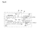
- a wavelet reverse transfer apparatus comprises a shift register for successively shifting input data by two pixels, and storing data for at least two pixels; a first decoding filter for decoding output data from the shift register, and outputting odd-number decoded coefficient data; a second decoding filter for decoding output data from the shift register, and outputting even-number decoded coefficient data; a data storage means for storing the decoded coefficient data output from the first decoding filter and the second decoding filter; and a main control means for controlling a sequence of wavelet reverse transform.
- the main control means controls a process of buffering the data stored in the data stored means by the shift register and a process of storing the coefficient data, which are decoded and up-sampled by the decoding filters, while controlling the address and the processing size in the data storage means for each frequency band, whereby the input data is subjected to wavelet reverse transform.
- the above-mentioned wavelet reverse transform apparatus further comprises coefficient line memories capable of high-speed burst transfer, for storing decoded coefficient data output from the first and second decoding filters; and a direct memory access means for transferring data output from the coefficient line memories, for each line, to the data storage means, and transferring data stored in the data storage means to the shift register.
- the main control means outputs a control instruction to the direct memory access means so that the data stored in the data storage means is buffered by the shift register and the coefficient data, which are decoded and up-sampled by the decoding filters, are stored in the data storage means, while controlling the address and the processing size in the data storage means for each frequency band, whereby the input data is frequency-divided.
- the above-mentioned wavelet reverse transform apparatus further comprises a coefficient storage means capable of high-speed burst transfer of data on a memory array in the horizontal direction and the vertical direction; and a switching means for selecting, as a receiver of data output from the coefficient line memory, one of the data storage means and the coefficient storage means.
- the main control means outputs a control instruction to the direct memory access means so that one of the odd-number decoded coefficient data or the even-number decoded coefficient data is stored in the coefficient line memory while the other is directly burst-transferred to the coefficient storage means by the direct memory access means and, thereafter, the coefficient data stored in the coefficient line memory is transferred to the coefficient storage means by the direct memory access means, while controlling the address and the processing size in the coefficient storage means for each frequency band, whereby the input data is subjected to wavelet reverse transform.
- the above-mentioned wavelet reverse transform apparatus further comprises a selector for selecting data to be input to the first and second decoding filters, from the data storage means and the coefficient storage means.
- the main control means outputs a control instruction to the direct memory access means so that the coefficient data in the coefficient storage means in the horizontal direction or the vertical direction is decoded and transferred to the coefficient line memory and, thereafter, the decoded data stored in the coefficient line memory is successively burst-transferred to the coefficient storage means by the direct memory access means.
- the input data to the first and second coding filters are given one bit upper extension, compared with the input data to be subjected to wavelet reverse transform and stored in the coefficient storage means.
- the above-mentioned wavelet transform apparatus further comprises decoding filter for decoding wavelet-transformed data; and a decoded coefficient line memory for storing coefficient data decoded by the decoding filter.
- decoding filter for decoding wavelet-transformed data
- a decoded coefficient line memory for storing coefficient data decoded by the decoding filter.
- one of low-frequency coefficient data and high-frequency coefficient data stored in the data storage means is transferred to the decoded coefficient line memory.
- the other coefficient data is transferred to the decoding filter and, simultaneously, the coefficient data stored in the decoded coefficient line memory is transferred to the decoding filter and decoded and, thereafter, the decoded data is stored in the coefficient line memory.
- the decoded data stored in the coefficient line memory is transferred to one of the coefficient storage means and the data storage means.
- the main control means conducts the above-mentioned processing repeatedly, for each frequency band, while controlling the address and the processing size in the coefficient storage means.
- the above-mentioned wavelet transform apparatus further comprises a decoding filter for decoding wavelet-transformed data; and decoded coefficient line memory.
- a decoding filter for decoding wavelet-transformed data
- decoded coefficient line memory one of low-frequency coefficient data and high-frequency coefficient data stored in the data storage means is transferred to the decoded coefficient line memory.
- the other coefficient data is transferred to the decoding filter and, simultaneously, the coefficient data stored in the decoded coefficient line memory is transferred to the decoding filter and decoded and, thereafter, the decoded data is stored in the coefficient line memory.
- the decoded data stored in the coefficient line memory is transferred to the data storage means.
- the main control means conducts the above-mentioned processing repeatedly, for each frequency band, while controlling the address and the processing size in the coefficient storage means.
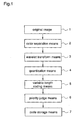
- Figure 1 is a flowchart for explaining an image data coding process in a coding method according to a first embodiment of the present invention.
- reference numeral 1 designates an original image
- numeral 2 designates a color separation means for separating the original image into a plurality of color components
- numeral 3 designates a wavelet transform means for wavelet-transforming the color-separated image data
- numeral 4 designates a quantization means for quantizing the transformed data
- numeral 5 designates a variable-length coding means for variable-length coding of the quantized data
- numeral 6 designates a priority judge means for deciding the priority for storage of the variable-length codes
- numeral 7 designates a code storage means for storing the variable-length codes according to the priority.
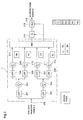
- FIG. 2 is a block diagram showing the detail of a Y coding means, a U coding means, or a V coding means in a subband coding system, and a position where the priority judge means 6 shown in figure 1 is applied.
- reference numeral 3 designates a wavelet transform means corresponding to the wavelet transform means 3 shown in figure 1, and the wavelet transform means 3 comprises HPFs 201, 205, and 207, LPFs 202, 206, and 208, and DSFs 203, 204, 209, 210, 211, and 212.
- Reference numeral 214 designates a quantization means corresponding to the quantization means 4 shown in figure 1
- numeral 215 designates a VLC corresponding to the variable-length coding means 5 shown in figure 1.
- the priority judge means 6 is connected to an output node of the VLC 215.
- Figures 3(a) and 3(b) are diagrams illustrating the structures of the priority judge means and the coding means, respectively.
- reference numeral 101 designates a CPU (Central Processing Unit) for giving priority to the variable-length codes
- reference numeral 102 designates a data storage means for storing variable-length codes coded by the variable-length coding means
- numeral 101 designates a CPU (Central Processing Unit) for deciding the priority of the variable-length codes
- numeral 102 designates a data storage means wherein the variable-length codes are written according to the priority decided by the CPU 101
- numeral 103 designates a CPU bus connecting the CPU 101 to the data storage means 102.
- reference numeral 301 designates a CPU performing hierarchical coding and generating two or more code sequences
- numeral 302 designates a data storage means in which the two or more code sequences generated by the CPU 301 are written
- numeral 303 designates a CPU bus connecting the CPU 301 with the data storage means 302.
- FIG 4 is a block diagram illustrating a structure of a coding apparatus for the coding method according to this first embodiment of the invention.
- reference numeral 400 designates a sampling means for sampling an RGB (Red Green Blue) signal of the original image
- numeral 401 designates a field storage means for storing the data sampled by the sampling means 400
- numeral 402 designates a color separation means for separating the data from the field storage means 401 into Y
- numeral 2 designates a color-separation block comprising the sampling means 400, the field storage means 401, and the color-separation means 402.
- This color-separation block 2 corresponds to the color-separation means 2 shown in figure 1.
- reference numerals 403, 404, and 405 designate a Y coding means, a U coding means, and a V coding means, respectively, performing wavelet-transform, quantization, and variable-length coding of a Y signal component, a U signal component, and a V signal component, which are output from the color-separation means 402.
- Reference numeral 406 designates a UV combining means for combining output codes from the U coding means 404 and the V coding means 405 to generate C component codes.
- the Y coding means 403, the U coding means 404, the V coding means 405, and the UV combining means correspond to the wavelet transform means 3, the quantization means 4, and the variable-length coding means 5 shown in figure 1.
- Reference numeral 407 designates a priority judge means corresponding to the priority judge means 6 shown in figure 1
- numeral 408 designates a code storage means corresponding to the code storage means 7 shown in figure 1.
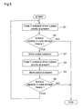
- FIG. 5 is a flowchart for explaining the coding method according to the first embodiment of the invention.
- S1 is a step of coding a subband wherein Y has the highest priority at present
- S2 is a step of judging whether there is a capacity for storage in the code storage means or not
- S3 is a step of storing the coded subband in the code storage means
- S4 is a step of coding a subband wherein C has the highest priority at present
- S5 is a step of storing the coded subband in the code storage means
- S6 is a step of judging whether there is a capacity for storage in the code storage means.
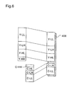
- Figure 6 is a schematic diagram illustrating data stored in the storage region of the code storage means when the coding is finished.
- the image data 1 representing the original image is subjected to color separation by the color separation means 2, whereby the image data 1 is separated into a plurality of color components. Then, each color component is divided into a plurality of layers of frequency components (subbands) by the wavelet transform means 3, and each layer (subband) is quantized by the quantization means 4 and coded by the variable-length coding means 5, whereby code data for each color and each layer is obtained.
- the code data is stored in the code storage means 7 according to the priority decided by the priority judge means 6.
- Figure 6 shows the code data stored in the code storage means 7.
- the total amount of the code data generated by the variable-length coding means 5 is larger than the amount of data that can be stored in the storage region of the storage means 408, some layers are not stored in the storage region.
- an image signal comprising RGB elements is sampled and A/D converted, for each pixel, by the sampling means 400, and stored in the field storage means 401. Then, the RGB signal stored in the field storage means 401 is converted to a YUV signal by the color separation means 402 and, at this time, U and V components are subjected to 1/2 down-sampling in the horizontal direction (4:2:2 subsampling). For example, when an input signal is sampled for 320 x 240 pixels, since 320 x 240 x 3 data is stored in the field storage means 401, the 4:2:2 subsampling result in 320 x 240 data for the Y component and 160 x 240 data for each of the U and V components.
- the Y component is subjected to wavelet transform, quantization, and variable-length coding by the Y coding means 403.
- the Y coding means has the same structure as that shown in figure 2. The structure of the Y coding means and the operation of each element are already described with respect to figure 2.
- the original image input to the input node 200 of the Y coding means 403 has 320 x 240 pixels, and each of the layers LL, LH, HL, and HH after the wavelet transform of the original image has the size of 160 x 120 pixels. Then, these layers LL, LH, HL, and HH are subjected to quantization and variable-length coding, individually, to obtain codes Y-LL, Y-LH, Y-HL, and Y-HH for the respective layers.
- the U coding means 404 and the V coding means 405 have the same structure as that shown in figure 2.
- the original image input to the input node 200 of the U (V) coding means 404 (405) has 320 x 240 pixels, and each of the layers LL, LH, HL, and HH after the wavelet transform has the size of 80 x 120 pixels. Then, these layers are individually subjected to quantization and variable-length coding.
- the UV combining means 406 combines a code of the U component in the LL layer (U-LL) with a code of the V component in the LL layer (V-LL) to produce a code C-LL. This processing is performed for each layer to produce color component codes C-LL, C-LH, C-HL, and C-HH.
- the priority judge means 407 is composed of the CPU 101, the data storage means 102, and the CPU bus 103 as shown in figure 3(a). The highest priority is given to the LL layer, followed by LH, HL, HH in this order. In each layer, the Y component has the priority over the C component.
- the respective codes, Y-LL to C-HH, have the code amounts shown in table 1.
- the size of the storage region in the code storage means 408 is 11000 bytes. Table 1 color ⁇ layer size Y-LL 3500 Y-LH 2000 Y-HL 2000 Y-HH 1000 C-LL 2000 C-LH 1000 C-HL 1000 C-HH 500
- the priority judge means 407 as a storage control means decides the priority of these codes Y-LL to C-HH, and the first code sequence and the second code sequence are stored from opposed ends, i.e., the head and the bottom, of the code storage means 408, respectively, according to the priority given to the respective codes. That is, the Y-LL code having the highest priority among the codes in the first and second code sequences is stored in the storage region of the code storage means 408 (hereinafter referred to simply as code storage means 408) from the head of the code storage means 408. Linear addresses are given to the storage region.
- the priority judge means 407 stores the following information: that is, the head address of the Y-LL code stored region in the code storage means 408, the size of the Y-LL code stored region, and the fact that the stored code is Y-LL.
- the priority judge means 407 stores the head address of the C-LL code stored region in the code storage means 408, the size of this region, and the fact that the stored code is C-LL.
- the priority judge means 407 calculates the tail address of the Y-LL code stored region to obtain the head address of the Y-LH code stored region in the code storage means 408, and the priority judge means 407 stores the head address of the Y-LH code stored region, the size of this region, and the fact that the stored code is Y-LH.
- the priority judge means 407 stores the head address of the storage region for each code, the size of this region, and information on the stored color component codes.
- the storage region of the code memory means 408 spends 10500 bytes, so that there is no capacity for the next 1000 byte C-HL code.
- the priority judge means 407 judges, as a storage control means, that an overlap will occur if the C-HL code is stored, and the Y-HL layer having the highest priority at present should be stored prior to other layers. So, the following three codes, C-HL, Y-HH, and C-HH, are not stored in the storage region of the code storage means 408 but abandoned.
- a narrow storage region is secured in the code storage means 408 by designating that region, and the priority judge means 407 transfers the head addresses of the Y-LL, Y-LH, Y-HL, C-LL, and C-LH code stored regions, the sizes of these regions, and information on the stored color component codes, which have been stored in the priority judge means, to the narrow storage region.
- the codes are successively read out and decoded according to the priority of the stored codes, whereby image data approximately equal to the original image data can be decoded.
- Y and C component codes which are obtained by converting an RGB color image to a YUV color image and performing wavelet transform, quantization, and variable-length coding to the YUV color image
- the Y component codes of large code amount are successively stored from the head of the storage means while giving priority to the low-frequency components
- the C component codes are successively stored from the bottom of the storage means while giving priority to the low-frequency component.
- image data can be stored in the storage means having a fixed storage capacity, at high efficiency, without losing much data, so that coding is performed at high efficiency with less memory capacity.
- the quality of the original image is hardly degraded.
- the wavelet transform is performed in the horizontal direction and the vertical direction, each for one time, to divide the image data into four layers LL, LH, HL, and HH, as shown in figure 2.
- the image data may be divided into more layers, for example, seven or ten layers, by repeating the wavelet transform for the LL layer of the lowest frequency.
- the layer for which the wavelet transform is repeated is not restricted to the LL layer.
- the priority may be given in the order of Y-LL, C-LL, Y-HL, Y-LH, C-HL, C-LH, Y-HH, and C-HH.
- the image signal is converted to the YUV signal, the representation of the color space is not restricted thereto.
- the coding method is not restricted thereto.
- a coding method wherein an image signal is divided into a plurality of components and MPEG coding is performed for each component is also within the scope of the present invention.
- a coding method and an coding apparatus according to a second embodiment of the invention will be described using signals 1, 2, 3, 4, 7, 8, and 9.
- Figure 7 is a block diagram obtained by simplifying the structure shown in figure 4.
- reference numeral 412 designates a color separation means corresponding to the color separation means 402 shown in figure 4
- numeral 413 designates a coding means corresponding to the Y coding means 403, the U coding means 404, the V coding means 405, and the UV combining means 406 shown in figure 4
- numeral 417 designates a priority judge means corresponding to the priority judge means 407 shown in figure 4
- numeral 418 designates a code storage means corresponding to the code storage means 408 shown in figure 4.
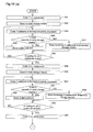
- FIG 8 is a flowchart for explaining a coding method according to this second embodiment in case where the priority judge means is constituted by a CPU.
- S11 is a step of coding a Y component subband having the highest priority at present
- S12 is a step of judging whether there is a capacity for storage in the code storage means
- S13 is a step of putting the coded subband in the code storage means
- S14 is a step of judging whether coding of all the Y component subbands is finished or not
- S15 is a step of omitting coding of the remaining Y component subbands
- S16 is a step of coding a C component subband having the highest priority at present
- S17 is a step of judging whether there is a capacity for storage in the code storage means
- S18 is a step of putting the coded subband in the code storage means
- S19 is a step of judging whether coding of all the C component subbands is finished or not
- S20 is
- Figures 9(a) to 9(f) are schematic diagrams for explaining a method of storing codes in the code storage means.
- an image signal comprising RGB elements is input to the sampling means 400, sampled, and stored in the field memory 401.
- the color separation means 412 converts the RGB signal stored in the field memory 401 to a YUV signal and outputs a Y component signal first.
- the Y component signal is subjected to wavelet transform, quantization, and variable-length coding by the coding means 413 shown in figure 7, resulting in codes for the respective layers, Y-LL, Y-LH, Y-HL, and Y-HH. The sizes of these codes are shown in table 1.
- the priority judge means 417 puts the codes Y-LL, Y-LH, Y-HL, and Y-HH in the first code sequence in the code storage means 418, from the head of the code storage means, according to the priority.
- the above-mentioned processing is achieved by repeating, for four times, a loop from step S11 to step S14 shown in figure 8.
- the size of the code storage means is 11000 bytes.
- Figure 9(a) shows the initial state of the code storage means 418
- figure 9(b) shows the code storage means 418 after the storage of the Y component codes.
- the color separation means 412 outputs a U component signal after 4:2:2 subsampling, and the U component signal is subjected to wavelet transform by the coding means 413 shown in figure 7.
- the same processing is performed for a V signal component.
- the YUV signal is subjected to subsampling at the ratio of 4:2:2.
- the data amount of the U (V) component becomes the half of the data amount of the Y component.
- wavelet transform for the V component can be performed using the same memory as a memory required for wavelet transform of the Y component, while storing wavelet transform coefficients for the U component in the memory.
- the coding means 413 shown in figure 7 selects the LL coefficient of the U component by a selection means 213 (refer to figure 2) and performs quantization and variable-length coding for the LL coefficient, resulting in a U component LL layer code.
- the coding means 413 performs quantization and variable-length coding for the LL coefficient of the V component to produce a V component LL layer code.
- the coding means 413 combines these codes to produce a C component LL layer code (hereinafter referred to as a C-LL code). This process corresponds to step S16.
- the amount of this C-LL code is 2000 bytes as shown in table 1.
- the priority judge means 417 puts the C-LL code in the code storage means 418 from the bottom of the code storage means. This process corresponds to steps S17, S18, and S19, and figure 9(c) shows the code storage means 418 when the C-LL code is stored.
- a C component LH layer code (hereinafter referred to as a C-LH code) is produced.
- the amount of this C-LH code is 1000 bytes as shown in table 1.
- the priority judge means 417 puts the C-LH code in the storage means 418 after the C-LL code.
- the C-LH code is written on a portion of the Y-HH code, and the other portion of the Y-HH code is destroyed.
- the priority judge means 417 performs layer-level rewriting. This process is achieved by performing a loop of steps S17, S20, and S21 for one time and then proceeding to step S8.
- Figure 9(d) shows the state of the code storage means 418 just before the storage of the C-LH code
- figure 9(e) shows the state where the Y-HH code is eliminated (step S21) and the C-LH code is stored.
- a C component HL layer code (hereinafter referred to as a C-HL code) is produced.
- the amount of this C-HL code is 1000 bytes as shown in table 1.
- the C-HL code is lower than the Y-HL code in the priority and the remaining capacity of the code storage means 418, i.e., a space between the Y-HL code and the C-LH code, is 500 bytes (figure 9(f)), the C-HL code is abandoned. This process corresponds to steps S17, S20, and S22. Further, HH coefficients of the U and V components are abandoned without quantization and variable-length coding, and the coding process in this field is ended. This is performed after step S22.
- Y-LL, Y-LH, and Y-HL codes are successively stored in the code storage means 418 from the head of the code storage means as shown in figure 10(b). This process is achieved by repeating a loop from step S11 to step S14 for three times. At this time, the remaining capacity of the code storage means 418 is 1000 bytes. Since it is judged in step S12 that the remaining capacity of the code storage means 418 is not sufficient for the next Y-HH code, this Y-HH code is abandoned. This process corresponds to step S15. Next, as shown in figure 10(c), the C-LL code is stored in the code storage means 418 by deleting the Y-HL code which is lower than the C-LL code in priority.
- This process is achieved by executing steps S16, S17, S20, S21, S17, and S18. Since the codes after the C-LH code are lower in priority than the Y-HL code, these codes are abandoned. This process is achieved by executing steps S16, S17, S20, and S22 and the coding process is ended.
- the capacity of the code storage means 418 is larger than the total amount of the generated codes, all codes can be stored.
- the coding and storage are achieved by repeating a loop of steps S11 to S14 for four times and repeating a loop of steps S16 to S19 for four times. That is, the Y component codes are stored in the code storage means 418 from the head as shown in figure 11(b) and, thereafter, the C component codes are stored from the bottom as shown in figure 11(c).
- codes in one field are stored in the code storage means having a fixed capacity.
- Y and C component codes which are obtained by converting an RGB color image to a YUV color image and performing wavelet transform, quantization, and variable-length coding to the YUV color image
- the Y component codes of large code amount are successively stored from the head of the storage means while giving priority to the low-frequency components
- the C component codes are successively stored from the bottom of the storage means while giving priority to the low-frequency component.
- image data can be stored in the storage means having a fixed storage capacity, at high efficiency, without losing much data, so that coding is performed at high efficiency with less memory capacity.
- the quality of the original image is hardly degraded.
- a third embodiment of the present invention relates to the priority judge means 417 and the code storage means 418 described for the second embodiment of the invention, so that description for the process steps before the priority judge step is omitted.
- the code storage means 418 is a memory having a capacity for storing codes in more than one field.
- Figures 12(a) to 12(e) are diagrams for explaining the manner of storing codes in the code storage means.
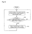
- FIG 13 is a flowchart showing the operation according to this third embodiment of the invention.
- S31 is a step of performing coding and storing generated codes in the code storage means in the same manner as described with respect to figure 8
- S32 is a step of judging whether there is a space between a Y stored region and a C stored region in the code storage means 418
- S33 is a step of moving the C stored region in the code storage means 418 to fill the space.
- FIG. 12(a) shows the entire memory of the code storage means 418 and a memory A assigned to the codes in one field.
- the codes are stored in the memory A (step S31).
- characters Y and C denote the Y component codes and the C component codes, respectively, stored in the memory A.
- the priority judge means 417 serving as a code transfer means and a region recovery means, fills a space between the Y component codes and the C component codes by transferring the C component codes to the space (steps S32 and S33).
- Figure 12(c) shows the state where no space is left between Y and C.
- the code storage means 418 assigns a memory B of the same capacity as the memory A to codes in the filed as shown in figure 12(d).
- the codes are stored in the memory B in the same manner as mentioned for the memory A.
- codes are stored in the successive memories in the code storage means, leaving no space.
- the YUV signal is sampled at 4:2:2 in this third embodiment, it may be sampled at 4:1:1.
- the amount of the C component codes which are produced by combining the U component codes and the V component codes, is less than the amount of the Y component codes. Therefore, when the C component codes are stored from the bottom of the code storage means to fill a space between the Y component codes and the C component codes, the amount of codes to be transferred is less than that in case where the Y component codes are stored from the bottom of the code storage means. Further, it is not necessary for the code storage means 418 to assign memories of the same capacity to all fields. That is, the capacity may be varied according to the amount of codes in each filed.
- Y and C component codes which are obtained by converting an RGB color image to a YUV color image and performing wavelet transform, quantization, and variable-length coding to the YUV color image
- the Y component codes of large code amount are successively stored from the head of the storage means while giving priority to the low-frequency components
- the C component codes are successively stored from the bottom of the storage means while giving priority to the low-frequency component.
- image data can be stored in the storage means having a fixed storage capacity, at high efficiency, without losing much data, so that coding is performed at high efficiency with less memory capacity.
- the quality of the original image is hardly degraded.
- signals in successive fields are stored with high efficiency while reducing the memory capacity for each field.
- Figure 14 is a block diagram illustrating a coding apparatus according to the fourth embodiment of the invention.
- the same reference numerals as those shown in figure 4 designate the same or corresponding parts.
- Reference numeral 409 designates a temporary storage means.
- image data is divided into three code sequences.
- Figures 15(a) to 15(c) are diagrams for explaining the manner of storing codes in the code storage means 408 and the temporary storage means 409.
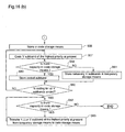
- FIG 16 is a flowchart illustrating the operation according to the fourth embodiment of the invention.
- S41 is a step of coding a Y-LL component
- S42 is a step of putting the coded Y-LL component in the code storage means.
- Steps S43 to S46 are steps similar to steps S11 to S14 shown in figure 8.
- S47 is a step of putting remaining Y subbands in the temporary storage means when it is judged in step S44 that the code storage means has no capacity
- S48 is a step of coding a U-LL component
- S49 is a step of putting the coded U-LL component in the code storage means
- S50 is a step of coding a U subband having the highest priority at present
- S51 is a step of judging whether the code storage means has a capacity or not
- S52 is a step of putting a coded subband in the code storage means
- S53 is a step of judging whether coding of all the U subbands is finished or not
- S54 is a step of storing remaining U subbands in the temporary storage means
- S55 is a step of coding a V-LL component
- S56 is a step of putting the coded V-LL component in the code storage means
- S57 is a step of coding a V subband of the highest priority at present
- the highest priority is given to the LL layer, followed by LH, HL, HH in this order.
- the Y component has the highest priority.
- the respective codes, Y-LL to V-HH have the code amounts shown in table 4.
- the size of the storage region 408 is 11500 bytes, and the size of the temporary storage means 409 is 12000 bytes.
- Table 4 color ⁇ layer size Y-LL 3500 Y-LH 2000 Y-HL 2000 Y-HH 1000 U-LL 2000 U-LH 1000 U-HL 1000 U-HH 1000 V-LL 2000 V-LH 1000 V-HL 1000 V-HH 1000
- Figure 15(a) shows the initial states of the code storage means 408 and the temporary storage means 409.
- the priority judge means 407 serving as a storage control means, puts the Y-LL code of the highest priority in the code storage means 408 and puts the Y-LH, Y-HL, and Y-HH codes in the temporary storage means 409 (steps S41 to S47 in figure 16).
- Figure 15(b) shows the state at this stage.
- the priority judge means 407 puts the U-LL code in the code storage means 408, next to the Y-LL code, and puts the U-LH, U-HL, and U-HH codes in the temporary storage means 409 (steps S48 to S54).
- Figure 15(c) shows the state where storage of the U component codes is completed. Next, the same processing is performed for the V component codes (steps S55 to S61).
- Figure 15(d) shows the state where all the color component codes are stored.
- the priority judge means 407 Since the code storage means 408 has a remaining capacity of 4000 bytes, the priority judge means 407, having a transfer judge function, selects the Y-LH, U-LH, and V-LH codes, code amounts of which are within 4000 bytes, from the codes stored in the temporary storage means, according to the priority, and transfers these codes to the code storage means 408 in this order (steps S62 and S63).
- Figure 15(e) shows the state where the transfer is finished. At this stage, the codes remaining in the temporary storage means 409 are abandoned, completing the coding process for one field.
- the fourth embodiment of the invention when Y and C component codes, which are obtained by converting an RGB color image to a YUV color image and performing wavelet transform, quantization, and variable-length coding to the YUV color image, are stored in a storage means, the Y-LL code having the highest priority among the Y component codes of large code amount is stored in the code storage means while remaining Y component codes are stored in the temporary storage means.
- the U-LL code having the highest priority among the U component codes and the V-LL code having the highest priority among the V component codes are stored in the code storage means so that no space is formed between the addresses, while other U and V component codes are stored in the temporary storage means.
- the Y-LH, U-LH, and V-LH codes which have relatively high priority and can be stored in the remaining capacity of the code storage means, are transferred from the temporary storage means to the code storage means. Therefore, even when image data is divided into three components, the image data can be stored in the storage means having a fixed storage capacity, at high efficiency, without losing much data. At decoding of the coded data, the quality of the original image is hardly degraded. Furthermore, according to the storage region control method mentioned above, signals in successive fields are stored with high efficiency while reducing the memory capacity for each field.
- a fifth embodiment of the invention will be described using figure 17.
- the structure according to this fifth embodiment is fundamentally identical to the structure according to the third embodiment except that the code storage means 428 has functions of calculating the total of codes in one filed, deciding a field for the next sampling according to the code amount, and indicating the decision to the sampling means 420. Further, the sampling means 420 performs sampling of the field decided by the code storage means 428.
- the operation of the coding apparatus will be described for a case where an image signal having 60 fields per second is coded, for a second, in a memory of 165000 bytes. 1/15 second is required for coding one field, and field sampling is performed at an interval of 4 fields or more.
- the sampling means 420 samples one field, and coding is performed while assigning a memory of 16500 bytes for one field.
- the code storage means 428 is provided with the following means: that is, means for calculating the memory capacity used by the coding means, means for raising the memory capacity to a prescribed lowest limit value when the calculated memory capacity is lower than this value, means for calculating a field interval in proportion to the memory capacity calculated by the memory capacity calculating means, means for designating the calculated field interval for the sampling means, means for detecting that raising is carried out by the memory capacity raising means, and means for controlling the hierarchical coding to increase the code amount when raising is detected.
- a field which is four fields after the previously sampled field, is sampled.
- a field which is five fields after the previously sampled field, is sampled.
- a field which is six fields after the previously sampled field, is sampled.
- a field which is six fields after the sampled field, may be sampled when the total of Y and C codes exceeds 11000 bytes.
- a sampling interval of 4 - 6 fields is the upper limit of a sampling interval that does not make a stiff motion.
- fields of an image signal are sampled at a designated time interval, the sampled data is subjected to hierarchical coding and stored in the code storage means. Meanwhile, the memory capacity used for the hierarchical coding is calculated. When the calculated memory capacity is less than a prescribed lowest limit value, this memory capacity is raised to the lowest limit value. When the raising of the memory capacity is detected, the hierarchical coding is controlled to increase the code amount, and a field interval in proportion to the calculated memory capacity is calculated and designated to the sampling means. Therefore, when the code amount is large, the field sampling interval is increased. When the code amount is small, the field sampling interval is reduced. Thereby, image signals in a prescribed period of time can be stored with high efficiency in a limited memory.
- the quantization factor may be changed so that the quantization error is reduced in the quantization means 214.
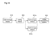
- a code storage means 518 stores an image signal coded by the coding method according to any of the first to fourth embodiments.
- the code storage means 518 is similar to the code storage means 408 and 418 and stores a sampling interval at coding.
- a decoding means 503 performs the reverse of the coding operation.
- Field storage means 501a and 501b store image signals, and an output from one of these field storage means is always represented by an image representation means 500.
- Y component codes and C component codes in the initial one field are successively taken out from the code storage means 518 and decoded by the deciding means 503 to reproduce the Y component, U component, and V component of the image signal.
- the reproduced color components are stored in the field storage means 501a.
- the decoding is performed on the assumption that the Y component layer destroyed by the C component layer at coding and the layers which are not coded are all zero.
- the image is presented to the image representation means 500 to which a YUV signal can be input as it is.
- codes in the second field are taken out from the code storage means 518, and the image signal is reproduced in the same manner as mentioned above and stored in the field storage means 501b.
- the field storage means that presents the image signal to the image representation means 500 is switched to 501b, and reproduction of the image signal for the third field is started. Thereafter, this processing is repeated as long as the next field is present in the code storage means 518.
- codes are read out from the storage means that stores the image signal coded by the coding method according to any of the first to fourth embodiments, and the codes are subjected to the reverse of the coding operation, i.e., decoded.
- the decoded image signal is written in one of the field storage means and read out from the other field storage means, and the writing and the reading are alternatingly repeated to reproduce the image signal.
- the image signal coded by the coding method according to any of the first to fourth embodiments is reproduced.
- the field interval for switching the field storage means is fixed at a multiple of the sampling interval stored in the code storage means 518, high-speed reproduction or slow reproduction is possible.
- an RGB signal can be input to the image representation means when means for converting the YUV signal into an RGB signal is connected before or after the field storage means.
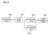
- a code storage means 528 stores an image signal coded by the coding method according to the fifth embodiment.
- the code storage means 528 is similar to the code storage means 428 according to the fifth embodiment and stores a sampling interval at coding.
- Y component codes and C component codes in the initial one field are successively taken out from the code storage means 518 and decoded by the deciding means 503 to reproduce the Y component, U component, and V component of the image signal.
- the reproduced color components are stored in the field storage means 501a.
- the decoding is performed on the assumption that the Y component layer destroyed by the C component layer at coding and the layers which are not coded are all zero.
- the image is presented to the image representation means 500 to which a YUV signal can be input as it is.
- codes in the second field are taken out from the code storage means 528, and the image signal is reproduced in the same manner as mentioned above and stored in the field storage means 501b.
- the field storage means that presents the image signal to the image representation means 500 is switched to 501b, and reproduction of the image signal in the third field is started. Thereafter, this processing is repeated as long as the next field is present in the code storage means 528.
- codes are read out from the storage means that stores the image signal coded by the coding method according to the fifth embodiment and the sampling interval, and the codes are subjected to the reverse of the coding operation, i.e., decoded.
- the decoded image signal is written in one of the field storage means and read out from the other field storage means, and the writing and the reading are alternatingly repeated to reproduce the image signal.
- the image signal is reproduced at the same speed as the original image signal even though the field for sampling is not fixed.
- the field interval for switching the field storage means is fixed at a multiple of the sampling interval stored in the code storage means 528, high-speed reproduction or slow reproduction is possible.
- an RGB signal can be input to the image representation means when means for converting the YUV signal into an RGB signal is connected before or after the field storage means.
- wavelet transform is employed for the coding method and the coding apparatus.
- the characteristic of the wavelet transform i.e., repeated frequency-division of image data for each frequency band, is utilized, whereby the circuit scale of hardware employed for the coding method and apparatus according to the first to fifth embodiments is further reduced.
- processing of an input image I1 by HPFs, LPFs, and subsamplers or processing of a transformed image I3 obtained by horizontal frequency division of the input image I1 by HPFs, LPFs, and subsamplers shown in figure 47 is realized by a memory storing a pair of image data and transformed data, HPFs, HPFs, and subsamplers.
- FIG 20 is a block diagram illustrating a wavelet transform apparatus according to the eighth embodiment of the invention.
- reference numeral 601 designates a CPU for controlling the entire system
- numeral 602 designates a data storage element for storing image data and coefficient data obtained by wavelet transform of the image data
- numeral 603 designates a CPU bus
- numeral 701 designates a shift register unit for storing the input data for 6 pixels, by two pixels in parallel
- numeral 702 designates a low-pass filter (LPF) for extracting a low-frequency component from the data from the shift register unit 701 and outputting the data as L coefficient data
- numeral 703 designates a high-pass filter (HPF) for extracting a high-frequency component from the data from the shift register unit 701 and outputting the data as H coefficient data.
- LPF low-pass filter
- HPF high-pass filter
- Figures 21(a)-21(f) show process steps of dividing an input image into a plurality of frequency subbands.
- Image data to be subjected to wavelet transform (figure 21(a)) is once stored in the data storage element 602 on the CPU bus 603.
- the CPU 601 transfers horizontal line data 1 (figure 21(a)) in the image data stored in the data storage element 602, through the CPU bus, to the shift register unit 701.
- SSKFs symmetric short kernel filters
- Figures 22(a) and 22(b) show the LPF and the HPF, respectively.
- reference numerals 702a, 702b, 702d, 702h, and 702i designate adders
- numeral 702c and 702e designate multipliers multiplying an input by 2
- numeral 702j designates a divider dividing an input by 8
- numerals 702f and 702g designate complementers outputting a complement of 2.
- reference numerals 703a and 703d designate adders
- numeral 703b designates a complementer outputting a complement of
- numeral 703c designates a multiplier multiplying a input by 2
- numeral 703e designates a divider dividing an input by 2.
- the shift register unit 701 shown in figure 20 is constituted by a register array 701x comprising registers 701f, 701d, and 701b and a register array 701y comprising registers 701e, 701c, and 701a.
- pixels Pn-2, Pn-1, Pn, Pn+1, Pn+2, Pn+3, Pn, ... are input, by two pixels as a unit, to the shift register unit 701, pixels Pn-1, Pn+1, Pn+3, ... are input to an input terminal of the register array 701x while pixels Pn-2, Pn, Pn+2, ... are input to an input terminal of the register array 701y.
- the image data transferred to the shift register unit 701 is output toward the LPF 702 and HPF 703, whereby the image data is frequency-divided into L coefficient data and H coefficient data by two pixels.
- the L and H coefficient data are once latched in the registers 704 and 705 and transferred, by the CPU 601, to the transformed line data storage regions in the data storage element 602.
- the H and L coefficient data are transferred to the line data storage regions of the input image, whereby these coefficient data are stored in the addresses for the L coefficient data 1 and H coefficient data 1 shown in figure 21(b).
- the image data shown in figure 21(a) is stored as shown in figure 21(c), after the frequency division.
- the CPU 601 transfers vertical line data 2 (figure 21(d)) of the L coefficient data 1 in the data storage element 602, through the CPU bus 603, to the shift register unit 701. Then, the image data transferred to the shift register unit 701 is output toward the LPF 702 and the HPF 703, whereby the image data is frequency divided into L coefficient data and H coefficient data by two pixels. Then, the H and L coefficient data are transferred, by the CPU 601, to the transformed line data storage regions in the vertical direction in the data storage element 602.
- the H and L coefficient data are transferred to the vertical line data storage regions of the input image, whereby these coefficient data are stored in the addresses for the L coefficient data 2 and the H coefficient data 2 shown in figure 2(e).
- the coefficient data shown in figure 21(d) are stored as shown in figure 21(f) after the frequency division.
- the CPU 601 repeats the frequency division to transform the input image data to wavelet coefficient data which is divided into a plurality of subbands as shown in figure 48.
- FIG. 23 A flowchart of the above-mentioned operation is illustrated in figure 23.
- the CPU 601 transfers the image data in the data storage element 602 through the shift register unit 701 to the LPF 702 and the HPF 703, whereby the simultaneous 1/2 subsampling and frequency division are performed recursively for each frequency subband. Therefore, a wavelet transform apparatus is realized by small-sized hardware, and the apparatus is easily controlled.
- FIG 24 is a block diagram illustrating the entire structure of a wavelet transform apparatus according to a ninth embodiment of the invention.
- the same reference numerals as those shown in figure 20 designate the same or corresponding parts.
- the structure shown in figure 24 is different from the structure shown in figure 20 in that a coefficient line memory (coefficient FIFO) 74 (in figure, coefficient FIFO1) for storing an output from a LPF 72, a coefficient line memory (coefficient FIFO) 75 (in figure, coefficient FIFO2) for storing an output from a HPF 73, and a CPU bus DMAC (Direct Memory Access Controller) 601a for performing DMA (Direct Memory Access) transfer of data are added.
- the DMAC 601a may be included within the CPU 601.
- FIG 25 is a block diagram illustrating the LPF 72 and the HPF 73 in more detail.
- the LPF 72 comprises the shift register unit 701, the LPF 702, and the register 704 shown in figure 20
- the HPF 73 comprises the shift register unit 701, HPF 703, and the register 705 shown in figure 20.
- Image data to be subjected to wavelet transform (figure 21(a)) is once stored in the data storage element 602 on the CPU bus 603.
- the CPU bus DMAC 601a transfers, by DMA transfer, horizontal line data 1 (figure 21(a)) in the image data stored in the data storage element 602, through the CPU bus, to the LPF 72 and the HPF 73, whereby L coefficient data and H coefficient data, which are frequency-divided by two pixels by the LPF 72 and the HPF 73, are stored in the coefficient FIFO 74 and the coefficient FIFO 75, respectively.
- the CPU bus DMAC 601a transfers, by DMA transfer, the coefficient data stored in the coefficient line memories 74 and 75 successively to the data storage element 602.
- the L and H coefficient data so transferred are stored in an address for L coefficient data 1 and an address for H coefficient data 1, respectively.
- the CPU bus DMAC 601a repeats the frequency division and the DMA transfer, whereby the image data is transformed to wavelet-transformed data divided into a plurality of frequency subbands as shown in figure 48.
- FIG. 26 A flowchart of the above-mentioned operation is illustrated in figure 26.
- the apparatus is not provided with the coefficient FIFO 74 and the coefficient FIFO 75, when the line data in the input image data region in the data storage element is successively frequency-divided and then stored in the region where the original line data has been stored, since the processing is performed by two pixels, line data which is not read out yet is destroyed.
- the apparatus since the apparatus is provided with the coefficient FIFO 74 and the coefficient FIFO 75, when the line data in the input image data region in the data storage element is frequency-divided, the coefficient data is once stored in the FIFO. Therefore, it is possible to restore the line data in the region where the original line data has been stored, so that the wavelet-transformed data region is dispensed with, whereby the memory efficiency is improved.
- the image data stored in the data storage element 602 is transferred through the shift register unit 701 to the LPF 702 and the HPF 703, whereby the simultaneous 1/2 subsampling and frequency division are performed recursively for each frequency subband. Therefore, a small-sized and easily controllable wavelet transform apparatus is realized. Furthermore, since the L coefficient data and the H coefficient data are successively DMA-transferred to the data storage element, the address calculation is facilitated.
- a memory capable of burst transfer in the horizontal direction such as a DRAM (Dynamic Random Access Memory), is employed as the data storage element 602, the data transfer speed in the horizontal direction is increased.
- the data transfer speed can be increased in both the horizontal and vertical directions. As a result, a high-speed wavelet transform apparatus is realized.
- a memory capable of burst transfer in both the horizontal and vertical directions such as an SRAM (Static Random Access Memory)
- SRAM Static Random Access Memory
- Figure 27 is a block diagram illustrating the entire structure of a wavelet transform apparatus according to a tenth embodiment of the invention.
- the same reference numerals as those shown in figure 24 designate the same or corresponding parts.
- the apparatus shown in figure 27 includes, besides the CPU bus 603 having a bit width of two pixels, a local bus 609 having a bit width of one pixel.
- Reference numeral 607 designates a coefficient storage element for storing frequency-divided L coefficients and H coefficients
- numeral 78 designates a switch for switching receivers of output data from the coefficient line memories 74 and 75
- numeral 79 designates a selector for selecting data to be input to the LPF 72 and the HPF 73 from the data storage element 602 and the coefficient storage element 607
- numeral 606a designates a local bus DMAC for DMA transfer of data.
- Image data to be subjected to wavelet transform (figure 21(a)) is once stored in the data storage element 602 on the CPU bus 603.
- the CPU bus DMAC 601a transfers, by DMA transfer, horizontal line data 1 (figure 21(a)) in the image data stored in the data storage element 602, through the CPU bus 603, to the LPF 72 and the HPF 73.
- the selector 79 selects the CPU bus 603.
- L coefficient data which is frequency-divided by two pixels by the LPF 72 and the HPF 73, are transferred directly to the coefficient storage element 607 (figure 21(b)). Meanwhile, H coefficient data is stored in the coefficient line memory 75. The H coefficient data in the coefficient line memory 75is transferred to the coefficient storage element 607 after the transfer of the L coefficient data to the coefficient storage element 607 is completed (figure 21(b)). At this stage, the switch 78 selects the local bus 609.
- the L and H coefficient data in the coefficient storage element 607 are stored as shown in figure 21(c) by repeating frequency division of the image data shown in figure 21(a).
- the coefficient data shown in figure 21(c) is subjected to vertical frequency division.
- the CPU 601 successively reads out vertical line data (figure 21(d)) of the L coefficient data in the coefficient storage element 607 and transfers the data to the LPF 72 and the HPF 73.
- the selector 79 selects the local bus 609.
- the L coefficient data which is frequency-divided by two pixels, is stored in the coefficient line memory 74 (in figure, FIFO1), and the H coefficient data are stored in the coefficient line memory 75 (in figure, FIFO2).
- the L coefficient data in the coefficient line memory 74 is transferred to the coefficient storage element 607 (figure 21(e)) and, subsequently, the H coefficient data in the coefficient line memory 75 is transferred to the coefficient storage element 607 (figure 21(e)).
- the L and H coefficient data in the coefficient storage element 607 are stored as shown in figure 21(f) by repeating the frequency division of the image data shown in figure 21(d).
- the input image data is frequency-divided into L and H coefficient data as shown in figure 48, whereby wavelet transform is completed.
- the CPU 601 can perform another processing using the CPU bus 603.
- FIG 28 A flowchart of the above-mentioned operation is illustrated in figure 28.
- the CPU 601 has a DMA function
- the data storage element 602 comprises a memory capable of burst transfer for memory access in the horizontal direction, such as DRAM
- the coefficient storage element 607 comprises a memory capable of burst transfer for memory access in both the horizontal and vertical direction, such as SRAM
- the coefficient line memories 74 and 75 are constituted by FIFOs.
- the image data stored in the data storage element 602 is subjected to frequency division at the DMA cycle of the CPU 601 and stored, as coefficient data, in the coefficient line memories 74 and 75, and the coefficient data is burst-transferred to the coefficient storage element 607 by the switch 78.
- the coefficient data stored in the coefficient storage element 607 is selected by the selector 79, the coefficient data can also be subjected to frequency division at the DMA cycle. Since the frequency division and the data transfer are performed by pipeline processing using the above-mentioned hardware structure, high-speed frequency division of image data is possible. Further, since the horizontal and vertical frequency division of image signal is performed recursively, a wavelet transform apparatus is realized by small-sized hardware, and the apparatus is easily controlled.
- a local bus having a bit width of one pixel is employed, if an SRAM, input and output of which have a bit width of two pixels, can be used as the coefficient storage element, a local bus having a bit width of two pixels may be employed.
- FIG. 29 is a block diagram illustrating the entire structure of a wavelet reverse transform apparatus according to the eleventh embodiment of the invention.
- Reference numerals 801 and 602 designate decoding filters for decoding L coefficient data and H coefficient data stored in the data storage element 602 to the original image
- numerals 804 and 805 designate registers for latching coefficient data output from the decoding filters 801 and 802, respectively.
- Figures 31(a) and 31(b) show the structures of the decoding filters 801 and 802, respectively.
- reference numerals 801a and 801b designate adders
- numeral 801c designates a divider dividing an input by 4.
- reference numerals 802a, 802b, 802f, 802h, and 802j designate adders
- numerals 802c and 802e designate multipliers multiplying an input by 2
- numeral 802d designates a complementer outputting a complement of 2 of an input
- numeral 802g designates a divider dividing an input by 8
- numeral 802i designates a divider dividing an input by 2.
- Figures 30(a) to 30(c) show the process of decoding a wavelet-transformed image.
- the wavelet-transformed image is stored in the data storage element 602 as shown in figure 30(a).
- the LLLLLL coefficient data 1 is read out in the vertical direction and transferred to the shift register unit 701.
- the L and H coefficient data are transferred, pixel by pixel, to the decoding filters 801 and 802.
- Figures 31(a) and 31(b) show the structures of the decoding filters 801 and 802, respectively.
- P2n is given to odd-number data in the decoded coefficient line 1 (figure 30(a))
- P2n+1 is given to even-number data in the decoded coefficient line 1
- the decoded image data are stored in the registers 804 and 805, and the CPU 601 reads out the stored image data and transfers the data through the CPU bus 603 to the data storage element 602.
- the L and H coefficient data in the data storage element 602 can be restored to the original image data and transferred to the data storage element 602.
- FIG 32 A flowchart of the above-mentioned operation is shown in figure 32.
- the CPU 601 transfers the coefficient data stored in the data storage element 602 to the decoding filters 801 and 802, whereby wavelet reverse transform and up-sampling are simultaneously performed, and this processing is performed recursively for each frequency subband. Therefore, a wavelet reverse transform apparatus is realized with small-sized hardware, and the apparatus is easily controlled.
- Figure 33 shows the entire structure of a wavelet reverse transform apparatus according to a twelfth embodiment of the invention.
- Reference numeral 84 designates a coefficient line memory (in figure, FIFO1) for storing an output from the decoding filter 801
- numeral 85 designates a coefficient line memory (in figure, FIFO2) for storing an output from the decoding filter 802
- numeral 710 designates a coded L coefficient line memory
- numeral 601a designates a CPU bus DMAC for DMA transfer of data.
- the DMAC 601a may be included in the CPU 601.
- Figures 30(a) to 30(c) show the process of decoding a wavelet-transformed image.
- the wavelet-transformed image is stored in the data storage element 602 as shown in figure 30(a).
- the CPU bus DMAC 601a reads out the LLLLLL coefficient data 1 in the vertical direction and transfers the data to the decoding line memory 710.
- the L and H coefficient data are transferred, pixel by pixel, to the decoding filters 801 and 802.
- Figures 31(a) and 31(b) show the structures of the decoding filters 801 and 802, respectively.
- P2n is given to odd-number data in the decoded coefficient line 1 (figure 30(a))
- P2n+1 is given to even-number data in the decoded coefficient line 1
- the decoded image data are stored in the registers 804 and 805, and the CPU bus DMAC 601a reads out the stored image data and transfers the data through the CPU bus 603 to the data storage element 602.
- the L and H coefficient data in the data storage element 602 can be restored to the original image data and transferred to the data storage element 602.
- the image data stored in the data storage element 602 is transferred through the shift register unit 701 to the decoding filters 801 and 802, whereby wavelet reverse transform and up-sampling are simultaneously performed, and this processing is performed recursively for each frequency subband. Therefore, a wavelet reverse transform apparatus is realized with small-sized hardware, and the apparatus is easily controlled. Further, since the L coefficient data and the H coefficient data are successively DMA-transferred to the data storage element, the address calculation is simplified. When a memory capable of burst transfer in the horizontal direction, such as a DRAM, is employed as the data storage element 602, the data transfer speed in the horizontal direction is increased.
- a memory capable of burst transfer in the horizontal direction such as a DRAM
- the data transfer speed can be increased in both the horizontal and vertical directions. As a result, a high-speed wavelet transform apparatus is realized.
- Figure 35 is a block diagram illustrating a wavelet reverse transform apparatus according to a thirteenth embodiment of the invention.
- Reference numeral 609 designates a local bus
- numeral 807 designates a coefficient storage element 607 for storing frequency-divided L coefficients and H coefficients
- numeral 88 designates a switch for switching receivers of output data from the coefficient line memories 85 and 86
- numeral 807a designates a local bus DMAC for DMA transfer of data.
- Figures 30(a) to 30(c) show the process of decoding a wavelet-transformed image.
- the wavelet-transformed image is stored in the coefficient storage element 807 as shown in figure 30(a).
- the local bus DMAC 807a reads out the LLLLLL coefficient data 1 in the vertical direction and transfers the data to the decoding line memory 710.
- the L and H coefficient data are transferred, pixel by pixel, to the decoding filters 801 and 802.
- Figures 31(a) and 31(b) show the structures of the decoding filters 801 and 802, respectively.
- P2n is given to odd-number data in the decoded coefficient line 1 (figure 30(a))
- P2n+1 is given to even-number data in the decoded coefficient line 1
- the decoded image data are stored in the coefficient FIFO 905 and the coefficient FIFO 906, and the CPU bus DMAC 601a reads out the stored image data and transfers the data through the CPU bus 603 to the data storage element 602.
- the L and H coefficient data in the data storage element 602 can be restored to the original image data and transferred to the data storage element 602.
- serial to parallel conversion may be performed at a cycle twice of the DMA cycle to transfer 16 bits, whereby the transfer speed is further increased.
- the CPU 601 has a DMA function
- the data storage element 602 comprises a memory capable of burst transfer for memory access in the horizontal direction, such as DRAM
- the coefficient storage element 807 comprises a memory capable of burst transfer for memory access in both the horizontal and vertical direction, such as SRAM
- the coefficient line memories 905 and 906 are constituted by FIFOs. Therefore, the coefficient data stored in the coefficient storage element 807 are decoded at the DMA cycle of the CPU 601, stored in the coefficient line memories 905 and 906, and then burst-transferred to the coefficient storage element 807.
- decoded image data can be transferred to the data storage element 602 in similar manner.
- the CPU 601 has a DMA function
- the data storage element 602 comprises a memory capable of burst transfer for memory access in the horizontal direction, such as DRAM
- the coefficient storage element 807 comprises a memory capable of burst transfer for memory access in both the horizontal and vertical direction, such as SRAM
- the coefficient line memories 905 and 906 are constituted by FIFOs.
- image data stored in the data storage element 602 is subjected to wavelet reverse transform at the DMA cycle of the CPU 601, and stored, as coefficient data, in the coefficient line memories 905 and 906. Further, the coefficient data is burst-transferred to the coefficient storage element 807 by the switch 98.
- Figure 37 is a block diagram illustrating the entire structure of an apparatus according to a fourteenth embodiment of the invention.
- the same reference numerals as those shown in figures 27 and 35 designate the same or corresponding parts.
- the wavelet transform apparatus according to the tenth embodiment is combined with the wavelet reverse transform apparatus according to the thirteenth embodiment.
- FIG 38 A flowchart of the operation of this apparatus is shown in figure 38.
- the CPU 601 has a DMA function
- the data storage element 602 comprises a memory capable of burst transfer for memory access in the horizontal direction, such as DRAM
- the coefficient storage element 807 comprises a memory capable of burst transfer for memory access in both the horizontal and vertical direction, such as SRAM
- the coefficient line memories 905 and 906 are constituted by FIFOs. Therefore, image data stored in the data storage element 602 is subjected to frequency division at the DMA cycle of the CPU 601, and stored, as coefficient data, in the coefficient line memories 905 and 906, and the coefficient data is burst-transferred to the coefficient storage element 807. Further, the frequency division of coefficient data stored in the coefficient storage element 807 is performed in similar manner.
- coefficient data stored in the coefficient storage element 807 are decoded at the DMA cycle of the CPU 601, stored in the coefficient line memories 905 and 906, and then burst-transferred to the coefficient storage element 807. Further, decoded image data can be transferred to the data storage element 602 in similar manner.
- Figure 39 is a block diagram illustrating the entire structure of an apparatus according to a fifteenth embodiment of the invention.
- the same reference numerals as those shown in figure 37 designate the same or corresponding parts.
- the structure sown in figure 39 is different from the structure shown in figure 37 only in that an offset element 914 and a reverse offset element 915 are added, whereby the data width of the data bus (thick line in figure 39) which is not directly connected to the CPU bus 603 is increased to improve the operation accuracy.
- Figure 40 is a block diagram illustrating the structures of the decoding filters 82 and 83 shown in figure 39.
- the decoding filter 82 comprises a shift register unit 701 and a decoding filter 801
- the decoding filter 83 comprises the shift register unit 701 and a decoder filter 802.
- Figure 41(a) shows a case where Y data is extended
- figure 41(b) shows a case where UV data is extended.
- Y data besides the original 8-bit Y data, in order to calculate figures below the decimal point, 2 bits are given for lower extension, 1 bit is given for upper extension, and 1 bit is given as a code bit.
- UV data since the original 8-bit UV data includes a code bit, 2 bits are given for upper extension and 2 bits are given for lower extension to make the data with equal to the data width of Y data.
- Figures 42(a) to 42(c) show the assignment of the upper extension bits and the lower extension bits.
- Figure 43(a) shows the conversion of Y data.
- the lower extension bit is omitted.
- a combination of (b11,b10) shown in figure 43(a) is employed.
- the code bit is '1', since the Y data takes only a positive value, 0 is output.
- the code bit is '0' and the upper extension bit is '1', the maximum value 255 is output. In other cases, b9 - b2 are output.
- Figure 43(b) shows the conversion of UV data.
- the lower extension bit is omitted.
- a combination (b11,b10,b9) shown in figure 43(b) is employed.
- the code bit is '1', -128 is output.
- the code bit is '0' and at least one of the upper extension bits is '1', the maximum value 127 is output.
- (b11,b10,b9) are all '1', b9 - b2 are output.
- data stored in the data storage element 602 is DMA-transferred to the LPF 72 and the HPF 73, frequency-divided in these filters 72 and 73, and DMA-transferred to the coefficient storage element 807 and, thereafter, the above-mentioned frequency division is recursively performed by DMA transfer, whereby wavelet transform of data is carried out.
- coefficient data is DMA-transferred to the decoding filters 82 and 83, subjected to wavelet reverse transform in the filters 82 and 83, and DMA-transferred to the coefficient storage element 807 and, thereafter, the above-mentioned wavelet reverse transform is recursively performed by DMA transfer.
- Figures 44(a) and 44(b) are block diagrams illustrating structures according to a sixteenth embodiment of the invention.
- the same reference numerals as those shown in figure 39 designate the same or corresponding parts.
- the structure shown in figure 44(a) is obtained by removing the selectors 913a and 913b, the decoding coefficient line memory 710, and the decoding filters 82 and 83 from the structure shown in figure 39, and this apparatus is used only for wavelet transform.
- the structure shown in figure 44(b) is obtained by removing the selectors 913a and 913b, the offset element 914, the selector 79, the LPF 72, and the HPF 73 from the structure shown in figure 39, and this apparatus is used only for wavelet reverse transform.
- the data pixel value extended to 12-bit width can be restored to 8-bit width.
- data stored in the data storage element 602 is DMA-transferred to the LPF 72 and the HPF 73, frequency-divided in these filters 72 and 73, and DMA-transferred to the coefficient storage element 807 and, thereafter, the above-mentioned frequency division is recursively performed by DMA transfer, whereby wavelet transform of data is carried out.
- the apparatus operating as mentioned above when image data is transferred from the data storage 602 to the LPF 72 and the HPF 73, since the upper 1 bit is extended, the accuracy of the filter operation when the frequency division is performed is improved, whereby the quality of image data decoded from the wavelet-transformed data is improved.
- coefficient data obtained by the wavelet transform is DMA-transferred to the decoding filters 82 and 83, subjected to wavelet reverse transform in the filters 82 and 83, and DMA-transferred to the coefficient storage element 807 and, thereafter, the above-mentioned wavelet reverse transform is recursively performed by DMA transfer.
- the data width is extended, by upper 1 bit, from the data width at the wavelet transform. So, the image data can be reversely transformed with the extended bit width and, after the reverse transform, the extended bit width can be restored to the original bit width, whereby the quality of image data decoded from the wavelet-transformed data is improved.
- FIG 45 is a block diagram illustrating a wavelet transform apparatus according to a seventeenth embodiment of the invention.
- This structure is obtained by combining a wavelet transform apparatus as shown in figure 24 with a wavelet reverse transform apparatus as shown in figure 33.
- the CPU 601, the CPU bus DMAC 601a, the data storage element 602, and the CPU bus are common to the wavelet transform and the wavelet reverse transform, and selectors 179, 913a, and 913b are added.
- the selector 179 sends data from the CPU bus 603 to the LPF and HPF filters 72 and 73 or to the decoding filters 82 and 83.
- the selector 913a selects one of outputs from the LPF 72 and the decoding filter 82 and sends the data to the coefficient line memory 905, and the selector 913b selects one of outputs from the HPF 73 and the decoding filter 83 and sends the data to the coefficient line memory 906.
- the apparatus according to this seventeenth embodiment operates in similar manner to the wavelet transform apparatus shown in figure 24 and the wavelet reverse transform apparatus shown in figure 33. However, this apparatus performs one the wavelet transform and the wavelet reverse transform.
- the CPU 601 has DMA function
- the data storage element 602 is a DRAM capable of burst transfer for horizontal memory access
- the coefficient line memories 905 and 906 are FIFOs. Therefore, image data in the data storage element 602 can be frequency-divided at a DMA cycle of the CPU 601 and stored, as coefficient data, in the coefficient line memories 905 and 906.
Landscapes
- Engineering & Computer Science (AREA)
- Multimedia (AREA)
- Signal Processing (AREA)
- Physics & Mathematics (AREA)
- General Physics & Mathematics (AREA)
- Theoretical Computer Science (AREA)
- Mathematical Analysis (AREA)
- Mathematical Optimization (AREA)
- Mathematical Physics (AREA)
- Pure & Applied Mathematics (AREA)
- Algebra (AREA)
- Data Mining & Analysis (AREA)
- Computational Mathematics (AREA)
- General Engineering & Computer Science (AREA)
- Software Systems (AREA)
- Databases & Information Systems (AREA)
- Discrete Mathematics (AREA)
- Computing Systems (AREA)
- Compression Or Coding Systems Of Tv Signals (AREA)
- Compression Of Band Width Or Redundancy In Fax (AREA)
- Compression, Expansion, Code Conversion, And Decoders (AREA)
- Analogue/Digital Conversion (AREA)
Applications Claiming Priority (3)
| Application Number | Priority Date | Filing Date | Title |
|---|---|---|---|
| JP23370495 | 1995-09-12 | ||
| JP23370695 | 1995-09-12 | ||
| EP96114584A EP0763943A3 (de) | 1995-09-12 | 1996-09-12 | Kodierungsverfahren und Wavelettransformationsvorrichtung |
Related Parent Applications (1)
| Application Number | Title | Priority Date | Filing Date |
|---|---|---|---|
| EP96114584A Division EP0763943A3 (de) | 1995-09-12 | 1996-09-12 | Kodierungsverfahren und Wavelettransformationsvorrichtung |
Publications (1)
| Publication Number | Publication Date |
|---|---|
| EP1635579A2 true EP1635579A2 (de) | 2006-03-15 |
Family
ID=26531164
Family Applications (2)
| Application Number | Title | Priority Date | Filing Date |
|---|---|---|---|
| EP05025623A Withdrawn EP1635579A2 (de) | 1995-09-12 | 1996-09-12 | Kodierungsverfahren und Wavelettransformationsvorrichtung |
| EP96114584A Withdrawn EP0763943A3 (de) | 1995-09-12 | 1996-09-12 | Kodierungsverfahren und Wavelettransformationsvorrichtung |
Family Applications After (1)
| Application Number | Title | Priority Date | Filing Date |
|---|---|---|---|
| EP96114584A Withdrawn EP0763943A3 (de) | 1995-09-12 | 1996-09-12 | Kodierungsverfahren und Wavelettransformationsvorrichtung |
Country Status (4)
| Country | Link |
|---|---|
| US (1) | US6067383A (de) |
| EP (2) | EP1635579A2 (de) |
| KR (1) | KR100308703B1 (de) |
| TW (1) | TW355905B (de) |
Families Citing this family (45)
| Publication number | Priority date | Publication date | Assignee | Title |
|---|---|---|---|---|
| JP3213582B2 (ja) * | 1997-05-29 | 2001-10-02 | シャープ株式会社 | 画像符号化装置及び画像復号装置 |
| JP4251675B2 (ja) * | 1997-07-30 | 2009-04-08 | ソニー株式会社 | 記憶装置およびアクセス方法 |
| DE19734542C2 (de) * | 1997-08-01 | 1999-10-28 | Deutsche Telekom Ag | Verfahren zur Wavelet-basierten Bildkompression |
| SE9704020L (sv) * | 1997-11-04 | 1999-04-26 | Telia Ab | Metod för resursoptimering i ett data- och telekommunikationssystem |
| JP3861957B2 (ja) * | 1998-02-03 | 2006-12-27 | ソニー株式会社 | 記憶装置、並びに書き込み方法および読み出し方法 |
| US6940496B1 (en) * | 1998-06-04 | 2005-09-06 | Silicon, Image, Inc. | Display module driving system and digital to analog converter for driving display |
| US6711297B1 (en) * | 1998-07-03 | 2004-03-23 | University Of Pittsburgh - Of The Commonwealth System Of Higher Education | Methods and apparatus for dynamic transfer of image data |
| WO2000016260A1 (fr) * | 1998-09-11 | 2000-03-23 | Sony Corporation | Processeur de donnees et procede de conversion de sequences de donnees |
| JP3691393B2 (ja) * | 1998-11-04 | 2005-09-07 | 三菱電機株式会社 | 画像復号化装置、画像復号化方法及び画像符号化・復号化システム |
| JP3285331B2 (ja) * | 1999-04-12 | 2002-05-27 | オリンパス光学工業株式会社 | 画像記録装置および電子カメラ装置 |
| US7369161B2 (en) * | 1999-06-08 | 2008-05-06 | Lightsurf Technologies, Inc. | Digital camera device providing improved methodology for rapidly taking successive pictures |
| US8212893B2 (en) | 1999-06-08 | 2012-07-03 | Verisign, Inc. | Digital camera device and methodology for distributed processing and wireless transmission of digital images |
| US7372485B1 (en) | 1999-06-08 | 2008-05-13 | Lightsurf Technologies, Inc. | Digital camera device and methodology for distributed processing and wireless transmission of digital images |
| US6788820B2 (en) * | 1999-11-03 | 2004-09-07 | Lucent Technologies Inc. | Methods and apparatus for wavelet-based image compression |
| US7103357B2 (en) | 1999-11-05 | 2006-09-05 | Lightsurf Technologies, Inc. | Media spooler system and methodology providing efficient transmission of media content from wireless devices |
| WO2001054397A2 (en) * | 2000-01-21 | 2001-07-26 | Lightsurf Technologies, Inc. | Improved digital camera device with methodology for efficient color conversion |
| US7847833B2 (en) | 2001-02-07 | 2010-12-07 | Verisign, Inc. | Digital camera device providing improved methodology for rapidly taking successive pictures |
| JP3906630B2 (ja) * | 2000-08-08 | 2007-04-18 | ソニー株式会社 | 画像符号化装置及び方法並びに画像復号装置及び方法 |
| US6888970B2 (en) | 2001-01-18 | 2005-05-03 | Lightsurf Technologies, Inc. | Wavelet transformation engine |
| US6898323B2 (en) * | 2001-02-15 | 2005-05-24 | Ricoh Company, Ltd. | Memory usage scheme for performing wavelet processing |
| JP4067281B2 (ja) * | 2001-02-20 | 2008-03-26 | 三洋電機株式会社 | 画像処理方法とその方法を利用可能な画像符号化装置および画像復号装置 |
| US7305354B2 (en) | 2001-03-20 | 2007-12-04 | Lightsurf,Technologies, Inc. | Media asset management system |
| JP2002359846A (ja) * | 2001-05-31 | 2002-12-13 | Sanyo Electric Co Ltd | 画像復号方法および装置 |
| US6697521B2 (en) | 2001-06-15 | 2004-02-24 | Nokia Mobile Phones Ltd. | Method and system for achieving coding gains in wavelet-based image codecs |
| JP4267848B2 (ja) * | 2001-09-25 | 2009-05-27 | 株式会社リコー | 画像符号化装置、画像復号装置、画像符号化方法、及び、画像復号方法 |
| JP3984886B2 (ja) * | 2001-09-28 | 2007-10-03 | キヤノン株式会社 | データ変換装置、データ変換方法、コンピュータプログラム、記憶媒体 |
| US7724281B2 (en) | 2002-02-04 | 2010-05-25 | Syniverse Icx Corporation | Device facilitating efficient transfer of digital content from media capture device |
| US20050147396A1 (en) * | 2002-02-20 | 2005-07-07 | Koninklijke Philips Electronics N.V. | Flexible storage of media information |
| US6873349B2 (en) * | 2002-03-19 | 2005-03-29 | Fuji Photo Film Co., Ltd | Image-recording with image data shifting |
| US6925208B1 (en) | 2002-05-04 | 2005-08-02 | Stentor, Inc. | Methods and apparatus for partitioning transform data |
| US7239754B2 (en) * | 2002-07-16 | 2007-07-03 | Hiroshi Akimoto | Method, apparatus and system for compressing still images in multipurpose compression systems |
| US7051040B2 (en) * | 2002-07-23 | 2006-05-23 | Lightsurf Technologies, Inc. | Imaging system providing dynamic viewport layering |
| KR100515960B1 (ko) * | 2002-11-07 | 2005-09-21 | 삼성테크윈 주식회사 | 적응적 디지털 영상 기록기 및 그 제어 방법 |
| US7116833B2 (en) * | 2002-12-23 | 2006-10-03 | Eastman Kodak Company | Method of transmitting selected regions of interest of digital video data at selected resolutions |
| KR100734790B1 (ko) * | 2003-07-09 | 2007-07-03 | 닛본 덴끼 가부시끼가이샤 | 동화상 부호화 방법, 동화상 복호 방법, 동화상 부호화 장치, 동화상 복호 장치, 및 프로그램을 수록한 컴퓨터 판독가능 기록매체 |
| US7860309B1 (en) | 2003-09-30 | 2010-12-28 | Verisign, Inc. | Media publishing system with methodology for parameterized rendering of image regions of interest |
| JP4599917B2 (ja) * | 2004-07-09 | 2010-12-15 | ソニー株式会社 | 撮像装置 |
| WO2007100743A2 (en) | 2006-02-24 | 2007-09-07 | Verisign, Inc. | System and method for cross-carrier mobile device capability discovery |
| KR101366091B1 (ko) | 2006-03-28 | 2014-02-21 | 삼성전자주식회사 | 영상 부호화 및 복호화 방법과 장치 |
| WO2008007760A1 (fr) * | 2006-07-13 | 2008-01-17 | Nec Corporation | Dispositif de codage et de décodage, procédé de codage et procédé de décodage |
| JP4356030B2 (ja) * | 2007-05-17 | 2009-11-04 | ソニー株式会社 | 情報処理装置および方法 |
| JP4991907B2 (ja) * | 2010-05-11 | 2012-08-08 | キヤノン株式会社 | 画像処理装置、および、画像処理装置の制御方法 |
| JP2015195527A (ja) * | 2014-03-31 | 2015-11-05 | ソニー株式会社 | 画像処理装置、および画像処理方法 |
| US9904874B2 (en) * | 2015-11-05 | 2018-02-27 | Microsoft Technology Licensing, Llc | Hardware-efficient deep convolutional neural networks |
| JP6700798B2 (ja) * | 2016-01-13 | 2020-05-27 | キヤノン株式会社 | 撮像装置及びその制御方法 |
Family Cites Families (7)
| Publication number | Priority date | Publication date | Assignee | Title |
|---|---|---|---|---|
| DE69126565T2 (de) * | 1990-04-17 | 1998-01-02 | Matsushita Electric Ind Co Ltd | Verfahren zur Übertragung von Kodes mit variabler Länge |
| JP2630085B2 (ja) * | 1991-02-26 | 1997-07-16 | 松下電器産業株式会社 | 記録装置と再生装置 |
| US5122875A (en) * | 1991-02-27 | 1992-06-16 | General Electric Company | An HDTV compression system |
| US6256642B1 (en) * | 1992-01-29 | 2001-07-03 | Microsoft Corporation | Method and system for file system management using a flash-erasable, programmable, read-only memory |
| JPH0638198A (ja) * | 1992-05-19 | 1994-02-10 | Sony Corp | 画像信号伝送装置及び画像信号伝送方法 |
| US5410355A (en) * | 1993-04-02 | 1995-04-25 | Rca Thomson Licensing Corporation | Video signal processor including input codeword buffer for providing stored codewords to codeword priority analysis circuit |
| EP1802133A3 (de) * | 1995-03-15 | 2008-11-12 | Kabushiki Kaisha Toshiba | Kodier- und/oder Dekodiersysteme für Bewegtbilder |
-
1996
- 1996-09-12 US US08/713,072 patent/US6067383A/en not_active Expired - Fee Related
- 1996-09-12 EP EP05025623A patent/EP1635579A2/de not_active Withdrawn
- 1996-09-12 TW TW085111148A patent/TW355905B/zh not_active IP Right Cessation
- 1996-09-12 KR KR1019960040304A patent/KR100308703B1/ko not_active Expired - Fee Related
- 1996-09-12 EP EP96114584A patent/EP0763943A3/de not_active Withdrawn
Also Published As
| Publication number | Publication date |
|---|---|
| KR970019655A (ko) | 1997-04-30 |
| EP0763943A2 (de) | 1997-03-19 |
| EP0763943A3 (de) | 1999-07-14 |
| KR100308703B1 (ko) | 2001-11-30 |
| US6067383A (en) | 2000-05-23 |
| TW355905B (en) | 1999-04-11 |
Similar Documents
| Publication | Publication Date | Title |
|---|---|---|
| US6067383A (en) | Coding method, coding apparatus, wavelet transform apparatus, and wavelet reverse transform apparatus | |
| Tzou | Progressive image transmission: a review and comparison of techniques | |
| CN100568969C (zh) | 可逆子波变换和嵌入代码流处理方法 | |
| US6198848B1 (en) | Method and apparatus for compressing and storing data indicative of a full-color image | |
| EP0864135B1 (de) | Speicherung und wiedergewinnung von grossen digitalen bildern | |
| US6301392B1 (en) | Efficient methodology to select the quantization threshold parameters in a DWT-based image compression scheme in order to score a predefined minimum number of images into a fixed size secondary storage | |
| EP1148731B1 (de) | Dekoder, Steuermethode und Speichermedium für Bewegtbilder | |
| EP0985193B1 (de) | Verfahren und einrichtung zur auf wavelets basierten datenkompression | |
| US6603814B2 (en) | Video compression scheme using wavelets | |
| JPH07168809A (ja) | ウェーブレット変換方法及びウェーブレット変換回路 | |
| JP2000513895A (ja) | データを圧縮するための方法、装置およびシステム | |
| WO1992017036A1 (en) | Improved method and apparatus for coding motion pictures | |
| EP0570818A2 (de) | Vorrichtung und Verfahren zur Übertragung von Videosignalen | |
| US5883978A (en) | Image compressing method and image compressing apparatus | |
| GB2258781A (en) | Data compression | |
| US20080285874A1 (en) | Method and apparatus for processing image data | |
| JPH06189285A (ja) | 画像データ圧縮伸張装置における量子化・逆量子化回路 | |
| US5613091A (en) | Data compression | |
| JP4514169B2 (ja) | デジタル信号変換装置及び方法 | |
| US5805737A (en) | Image signal compressing device | |
| US6934420B1 (en) | Wave image compression | |
| JPH09139944A (ja) | 符号化方法,符号化装置,ウエーブレット変換装置およびウエーブレット逆変換装置 | |
| EP0767587B1 (de) | Hierarchische Kodierungs- Dekodierungs-Vorrictung mit Speichervorrichtung für ein digitales Bildsignal | |
| JPH0654317A (ja) | デジタル形式で画像信号を伝送するテレビジョンシステム | |
| US6754433B2 (en) | Image data recording and transmission |
Legal Events
| Date | Code | Title | Description |
|---|---|---|---|
| PUAI | Public reference made under article 153(3) epc to a published international application that has entered the european phase |
Free format text: ORIGINAL CODE: 0009012 |
|
| 17P | Request for examination filed |
Effective date: 20051124 |
|
| AC | Divisional application: reference to earlier application |
Ref document number: 0763943 Country of ref document: EP Kind code of ref document: P |
|
| AK | Designated contracting states |
Kind code of ref document: A2 Designated state(s): DE FR GB NL |
|
| RIN1 | Information on inventor provided before grant (corrected) |
Inventor name: GOTOH, SHOUICHIMATSUSHITA ELECTRIC IND. CO. LTD Inventor name: AOKI, NORIO Inventor name: UEHARA, HIROTOSHIMATSUSHITA ELECTRIC IND. CO. LTD Inventor name: TANIGUCHI, SHUUHEI |
|
| RAP1 | Party data changed (applicant data changed or rights of an application transferred) |
Owner name: PANASONIC CORPORATION |
|
| STAA | Information on the status of an ep patent application or granted ep patent |
Free format text: STATUS: THE APPLICATION HAS BEEN WITHDRAWN |
|
| 18W | Application withdrawn |
Effective date: 20090917 |