EP1635586A2 - Verfahren und Vorrichtung zur Übertragung von digitalen Daten in einem Kanal mit begrenzten Datenraten - Google Patents
Verfahren und Vorrichtung zur Übertragung von digitalen Daten in einem Kanal mit begrenzten Datenraten Download PDFInfo
- Publication number
- EP1635586A2 EP1635586A2 EP05111981A EP05111981A EP1635586A2 EP 1635586 A2 EP1635586 A2 EP 1635586A2 EP 05111981 A EP05111981 A EP 05111981A EP 05111981 A EP05111981 A EP 05111981A EP 1635586 A2 EP1635586 A2 EP 1635586A2
- Authority
- EP
- European Patent Office
- Prior art keywords
- transmission
- transmitter
- protocol
- data
- message
- Prior art date
- Legal status (The legal status is an assumption and is not a legal conclusion. Google has not performed a legal analysis and makes no representation as to the accuracy of the status listed.)
- Withdrawn
Links
Images

Classifications
-
- H—ELECTRICITY
- H04—ELECTRIC COMMUNICATION TECHNIQUE
- H04W—WIRELESS COMMUNICATION NETWORKS
- H04W28/00—Network traffic management; Network resource management
- H04W28/02—Traffic management, e.g. flow control or congestion control
- H04W28/06—Optimizing the usage of the radio link, e.g. header compression, information sizing, discarding information
-
- H—ELECTRICITY
- H04—ELECTRIC COMMUNICATION TECHNIQUE
- H04L—TRANSMISSION OF DIGITAL INFORMATION, e.g. TELEGRAPHIC COMMUNICATION
- H04L47/00—Traffic control in data switching networks
- H04L47/10—Flow control; Congestion control
-
- H—ELECTRICITY
- H04—ELECTRIC COMMUNICATION TECHNIQUE
- H04L—TRANSMISSION OF DIGITAL INFORMATION, e.g. TELEGRAPHIC COMMUNICATION
- H04L47/00—Traffic control in data switching networks
- H04L47/10—Flow control; Congestion control
- H04L47/36—Flow control; Congestion control by determining packet size, e.g. maximum transfer unit [MTU]
-
- H—ELECTRICITY
- H04—ELECTRIC COMMUNICATION TECHNIQUE
- H04L—TRANSMISSION OF DIGITAL INFORMATION, e.g. TELEGRAPHIC COMMUNICATION
- H04L67/00—Network arrangements or protocols for supporting network services or applications
- H04L67/01—Protocols
- H04L67/04—Protocols specially adapted for terminals or networks with limited capabilities; specially adapted for terminal portability
-
- H—ELECTRICITY
- H04—ELECTRIC COMMUNICATION TECHNIQUE
- H04L—TRANSMISSION OF DIGITAL INFORMATION, e.g. TELEGRAPHIC COMMUNICATION
- H04L67/00—Network arrangements or protocols for supporting network services or applications
- H04L67/50—Network services
- H04L67/56—Provisioning of proxy services
- H04L67/565—Conversion or adaptation of application format or content
-
- H—ELECTRICITY
- H04—ELECTRIC COMMUNICATION TECHNIQUE
- H04W—WIRELESS COMMUNICATION NETWORKS
- H04W28/00—Network traffic management; Network resource management
- H04W28/02—Traffic management, e.g. flow control or congestion control
-
- H—ELECTRICITY
- H04—ELECTRIC COMMUNICATION TECHNIQUE
- H04W—WIRELESS COMMUNICATION NETWORKS
- H04W8/00—Network data management
- H04W8/02—Processing of mobility data, e.g. registration information at HLR [Home Location Register] or VLR [Visitor Location Register]; Transfer of mobility data, e.g. between HLR, VLR or external networks
- H04W8/04—Registration at HLR or HSS [Home Subscriber Server]
-
- H—ELECTRICITY
- H04—ELECTRIC COMMUNICATION TECHNIQUE
- H04W—WIRELESS COMMUNICATION NETWORKS
- H04W88/00—Devices specially adapted for wireless communication networks, e.g. terminals, base stations or access point devices
- H04W88/18—Service support devices; Network management devices
- H04W88/181—Transcoding devices; Rate adaptation devices
-
- H—ELECTRICITY
- H04—ELECTRIC COMMUNICATION TECHNIQUE
- H04L—TRANSMISSION OF DIGITAL INFORMATION, e.g. TELEGRAPHIC COMMUNICATION
- H04L69/00—Network arrangements, protocols or services independent of the application payload and not provided for in the other groups of this subclass
- H04L69/08—Protocols for interworking; Protocol conversion
-
- H—ELECTRICITY
- H04—ELECTRIC COMMUNICATION TECHNIQUE
- H04W—WIRELESS COMMUNICATION NETWORKS
- H04W92/00—Interfaces specially adapted for wireless communication networks
- H04W92/04—Interfaces between hierarchically different network devices
- H04W92/12—Interfaces between hierarchically different network devices between access points and access point controllers
Definitions
- the subject of the present invention is a method and a transmission device that can essentially be used for transmitting digital data, in particular data formatted according to the GPRS standard.
- the invention will be implemented in the context of a data transmission to a mobile phone, for example to display on a screen of this mobile phone the results of a visit to a website.
- the invention is more generally intended for the adaptation of the protocol of the GPRS standard to the equipment used for radio transmissions of the GSM type.
- the necessary fixed equipment comprises, in a base station BS, a so-called BSC equipment, Base Station Controller, which controls the base station.
- This BSC equipment controls a base station transmitting equipment, BTS Base Transceiver Station, which provides a radio interface between the base station controller BSC and a mobile phone.
- a base station controller controls one or more BTS devices. It manages the radio resource: it allocates channels for calls and it makes the decisions of transfer of base station, The allocation of channel includes the designation of windows of time in the frames and carrier frequencies or encoding laws for the TDMA or CDMA type systems respectively (time division multiple access, code division multiple access respectively).
- the links In order to limit the cost of the transceiver stations with fixed receiver-transmitter BTS equipment, these do not perform any other processing than a digital-analog conversion processing and a modulation and / or amplification processing.
- the links In practice between the base station controllers, BSC, and the transceivers of these base stations, BTS, the links have channels calibrated at 16 kilobits per second, in fact 64 kilobits per second channels but capable of route each 4 lanes. Other flows could have been chosen. However, for reasons of industrial manufacture, the equipment in place and those to be installed are now realized with such a limit of flow
- the CS1, CS2, CS3 and CS4 coding schemes are able respectively to convey bit rates, in useful bits, equal to 8800 bits per second, 12800 bits per second, 15200 bits per second and 20800 bits per second.
- bit messages that can be transmitted for a period of 20 milliseconds are then 176 bits, 256 bits, 310 bits and 416 bits respectively, with a flow rate in the channel between the controller BSC and the base station BTS transceiver limited to 16 kilobits per second, the transmission time of these useful bits is respectively 12 milliseconds, 17 milliseconds, 21 milliseconds or 28 milliseconds In theory this transmission time is less than these values but was the need to incorporate an encapsulation of the bits transmitted on the channel to 16 Kilobits, the necessary to return these data and this signaling leads at the overall durations above.
- These different coding schemes are aimed that in 1500 byte frames (or 12 kilobits) the affected contribution to redundancy is less strong when going CS protocol - the protocol CS4.
- the object of the invention is to ensure, at least for the less well-protected CS3 type coding scheme, that the effective bit rate is greater than the bit rate of the better protected coding scheme CS2.
- the useful rate of this scheme CS3 will be equal to twelve thirteenths of the theoretical rate, that is to say 14.03 Kilobits per second. This leads approximately to a loss of 7.7% on the theoretical flow.
- the flow rate of the CS3 scheme remains 9.6% higher than that of the CS2 scheme.
- the CS3 scheme can then support a bit error rate of up to 8% without its flow is affected excessively.
- the payload will be reduced from the theoretical rate of 20.8 kilobits per second to 14.4 kilobits per second. That is, almost the same (but a bit better) than the CS3 schema. It should be noted, however, that this disadvantage is of little importance since the normal radio transmission conditions make this coding scheme most of the time impracticable. Indeed as this scheme is not protected by enough redundancy, bit error rate is very important. The flow then drops in a very important way
- the object of the invention is also to remedy these drawbacks in a particularly simple manner.
- the invention therefore relates to a transmission device comprising a first transmitter receiving from a transmitter data messages formatted according to a first protocol and converting data thus received into data formatted according to a second protocol, a second transmitter connected to the first transmitter, receiving the data messages formatted according to the second protocol and transmitting them, in a synchronous mode, to a receiver, a limited-rate transmission channel connecting the two transmitters, characterized in that, said data messages formatted according to said second protocol that may have different possible lengths said device comprises means for transmitting on said transmission channel at a limit rate and in a syrchione mode said data messages that may have different possible lengths
- FIG. 1 shows a transmission device according to the invention.
- This transmission device comprises a first transmitter 1 receiving from a transmitter 2 data messages formatted according to a first protocol.
- the transmitter 1 is a base station control circuit, BSC, of a base station 3.
- BSC base station control circuit
- the same control circuit 1 can govern one or more second transmitters such as 4, the second transmitters 4 are simply BTS radio receiver transceivers constituting a radio interface between the first transmitter and the BSC circuits 1 and receivers, telephones such as 5.
- the control circuit 1 comprises means, including processing units 6, implementing programs 7 to manage the communication of data between the BTS 4 and mobiles 5.
- GSM Global System for Mobile communications
- a BTS 4 receives by a transmission channel 9 data already formatted according to a GSM protocol.
- BTS 4 complex treatments are undertaken.
- FEC Forward Error Correction
- error detection methods The latter methods make it possible in particular to detect whether a received block is valid or not.
- the data are here symbolically transmitted to a digital to analog converter 10 of the BTS 4.
- This digital to analog converter 10 is also capable of performing variable gain modulation and amplification of radio signals intended for the mobile 5.
- a radio transmission part and a reception part
- a modulation and a digital analog conversion are set up.
- These circuits are very simple.
- Channel 9 also has the disadvantage of having been calibrated at a limited rate, here in a manner common to 16 Kilobits. This disadvantage in return has an advantage the equipment of the base stations can be standardized and be cheap.
- the transmitter 2 is here an emitter transmitting on a transmission channel 11 data signals formatted according to the GPRS standard, General Packet Radio Service - General Service for Transmission of Radio Packets.
- the GPRS service defines a packet-switched network architecture with mobility management and access by radio .
- a GPRS network can be connected to various fixed data networks based on different IP protocols (Internet Protocol - Internet Protocol but also X25 protocol one connection and CLNP (Connection Less Network Protocol).)
- IP protocols Internet Protocol - Internet Protocol but also X25 protocol one connection and CLNP (Connection Less Network Protocol).
- CLNP Connection Less Network Protocol
- FIG. 1 shows that the transmitter 2 comprises a GPRS support node 12 (SGSN Serving GPRS Support Node) which is connected to one or more base stations such as 3.
- the node 12 is connected to a packet transmission network 13 an X25 network or the Internet network for example, via a gateway support node 14 (GGSN, Gateway GPRS Support Node)
- the gateway node 14 can be connected to one or more data networks such as the network 13.
- the node 14 is a router that allows packets from external data networks to be routed, via the node 12, to the base station 3, in particular the control circuits 1 of this station. base 3.
- the first transmitter 1 receives the data according to a GPRS protocol from the transmitter 2, and transmits them to the second transmitter 4 according to a second protocol, here the GSM protocol.
- the second transmitter, the base station 4 transmits to the receiver 5.
- the protocol conversion could also be different from the adaptation mentioned above, or even be reduced to a simple transmission
- the second transmitter here the BTS 4
- the BTS 4 comprises a buffer 15 here preferably of the first-in first-out type. It is not necessarily of this type if the transmission to the mobile is in packet mode (if each packet has a serial number).
- a memory 15 has been shown in the form of a rotating memory with a write input 16 in the memory 15, and a read output 17 of this memory 15.
- the bus 9 is thus connected on the one hand to the input, 18 on the other hand to an input 18 for controlling the digital analog conversion, modulation, amplification and radio transmission circuits.
- the memory 15 is preferably of the first-in, first-out type, messages I to V being stored in this order before being extracted in this order In reception the same type of connection is realized.
- the memory 15 is agrementée a decoder 19, also connected to the bus 9, and capable of receiving a retransmission instruction of a message previously stored and has already been issued.
- the memory 15 comprises in its different cells messages of rank 0, 1, II, III, IV, V and so on.
- the message I is being sent by the circuits 10. After the transmission of the message I, the message II must be sent. Then message III and message IV and so on.
- the pointer 17 for reading the memory 15 addresses the different cells thereof to pick up these messages I, II, III, IV, V and so on. It can happen that the message of rank 0 has not been well received by the mobile 5.
- the decoder 19 by decoding an instruction can then either temporarily move the read pointer 17 so that it comes re-read at a given moment the message of rank 0, and therefore reissue, or provide the rewrite of the rank message 0 following the message of rank V in the memory 15, so that this message can be retransmitted later.
- the instruction thus executed is intended to avoid having to retransmit through the channel 9, at a limited rate, the content of the message 0 whose control circuit 1 knows that it was poorly received by the receiver 5, and that this knowledge of this bad reception occurs while the message 0 is still memorized in the memory 15 By acting thus it will be avoided to have to retransmit the message of rank 0 badly received twice on the bus 9.
- a control circuit 1 As much as it is possible for a control circuit 1 to control several BTS such as 4, it is possible for a control circuit 1 to govern, for the same BTS 4, several channels such as 9 supplying several buffers such as 15, by In this case, the efficiency of the improvement provided by the invention can be further increased. Indeed, according to an improved mode, it is expected with a new modulation to expect rates of 60 Kilobits per time window. In this case the radio modulation of the circuit 10 will be modified. Under these conditions, it may be possible to break the CS4 scheme. In this case, it will be possible to feed with the different channels such as the different memories 15 or 20 or more generally a common memory the message such as message 0, must then be repeated, there will then be no need for this message to be repeated on the same time window.
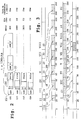
- FIG. 2 shows in summary the various coding schemes CS1 to CS4 that can be used to transmit data according to the GPRS protocol.
- 1500 byte frames ie 12 kilobits, are transmitted in packets.
- Each packet has an address portion 21, a payload portion 22, and a payload redundancy portion 23.
- each packet has synchronization SY indications, P transmission power, and signaling S1.
- the synchronization signals make it possible to clock the operation of the BTS 4. Here they are used at least to clock the pointer 17 for reading.
- the power signals P are in a known manner used to control the power operation of the transmission circuits 10 via the input 10.
- the signaling signals are signals of various types. and may include in particular in the invention instructions decodable by the decoder 19.
- CS1 From one scheme, CS1, to the other, CS4, the useful part of data becomes larger while the redundancy portion is reduced. This leads to useful rates ranging from 8800 bits per second to 20800 bits per second. Useful bits transmittable per 20 millisecond period then increase from 176 to 416 as indicated above. For each message thus designated transmission time, on a transmission channel at 16 Kilobits leads to hard ranging from 12 milliseconds to 28 milliseconds.
- the processing circuits 6 and 7 perform a processing 26 (LL RLC) of known type they are able to extract packets received on the bus and the bits useful to transmit on the bus 8. They transmit them according to termat GSM in them embellishing signals signaling
- Figure 3 shows the transmission mode in the state of the art and according to the invention respectively.
- messages to be transmitted numbered I to VIII and whose transmission times according to their coding scheme are recalled. These times are 12 milliseconds or 22 milliseconds in the example.
- a second line at the top of the figure we have shown the effects of the timing imposed by the direct implementation of the GPRS standard, without desynchronization, without waiting time.
- the second line shows the occupancy of channel 9 when it is controlled according to the GPRS standard. In this case, 20-millisecond time windows are provided.
- a data message for example message 1
- it must first be completely received in the circuits 1 before This is for example the case after 20 milliseconds for the message I, and this message I can be transmitted during a duration of 12 milliseconds during a second window between the dates between 32 milliseconds, end of transmission of the message I, and 40 milliseconds, beginning of the third window, the channel 9 is unoccupied.
- the message II that was received between the dates 12 milliseconds and 34 milliseconds can be transmitted during the third time window beginning at the date 40 milliseconds, but the message It is transmitted for 22 milliseconds, partially during the fourth time window from 60 milliseconds to 80 milliseconds.
- the timing of 20 milliseconds has been abandoned for channel 9. Consequently, in this channel 9, the transmissions are in asynchronous mode.
- the third line of FIG. 8 shows that the transmission of the messages 1 to X is done by making better use of the bit rate.
- channel 9. shows both the occupation of the channel 9 and the input of the memory 15.
- the buffer memory 15 is loaded by the message 1 for a time between the dates 20 milliseconds and 32 milliseconds.
- no message can be emitted by the BTS 4 to the receiver.
- the message 1, 12 milliseconds is transmitted during the time window of 40 to 60 milliseconds.
- a buffer memory preferably of the first-in first-out type
- the principle is then as follows: it is stored in advance, in asynchronous mode, in the transmitter BTS the blocks to transmit. Then they are taken in the buffer at the rate corresponding to the GSM transmission.
- GSM transmission a theoretical maximum rate equal to 250 kilobits per second between a BTS transmitter and a mobile is possible (in the case where all the time slots of the frames would be assigned to the same mobile phone).
- the GSM transmission mode has a bit rate greater than 16 kilobits. With such a superior flow.
- the message II available in the memory 15 can be sent by the base station towards the mobile 5. It can easily be verified that the message V, whose transmission starts at the date 120 milliseconds , could have been sent to the memory between the period between 98 and 120 milliseconds.
- the message VI whose reception by the men 5 ends at the date 144 milliseconds, is unavailable for transmission during the next window from 140 to 160 milliseconds. This must be neutralized. It will be appreciated that the disable and control commands of the memory 15 may be sent as signaling data in the messages transmitted and decoded by the decoder 19.
- the message will only be sent by the base station between the dates. 160 and 180 milliseconds. So we see that at the date 260 milliseconds. with the invention, it was possible to send the message X whereas with the solution of the state of the art only the messages I to VII had been sent. This clearly shows the flow gain provided by the invention. It can be seen that this flow gain is achieved despite the low flow rate of the channel 9 and also respecting the timing of the GPRS mode.
Landscapes
- Engineering & Computer Science (AREA)
- Computer Networks & Wireless Communication (AREA)
- Signal Processing (AREA)
- Databases & Information Systems (AREA)
- Mobile Radio Communication Systems (AREA)
- Data Exchanges In Wide-Area Networks (AREA)
- Optical Communication System (AREA)
Applications Claiming Priority (2)
| Application Number | Priority Date | Filing Date | Title |
|---|---|---|---|
| FR9914634A FR2801466B1 (fr) | 1999-11-22 | 1999-11-22 | Procede et dispositif de transmission pour des donnees numeriques |
| EP00403200A EP1102504B1 (de) | 1999-11-22 | 2000-11-16 | Verfahren und Vorrichtung zur Übertragung in einem Kanal mit begrenzten Datenraten |
Related Parent Applications (1)
| Application Number | Title | Priority Date | Filing Date |
|---|---|---|---|
| EP00403200A Division EP1102504B1 (de) | 1999-11-22 | 2000-11-16 | Verfahren und Vorrichtung zur Übertragung in einem Kanal mit begrenzten Datenraten |
Publications (2)
| Publication Number | Publication Date |
|---|---|
| EP1635586A2 true EP1635586A2 (de) | 2006-03-15 |
| EP1635586A3 EP1635586A3 (de) | 2007-06-13 |
Family
ID=9552359
Family Applications (2)
| Application Number | Title | Priority Date | Filing Date |
|---|---|---|---|
| EP00403200A Expired - Lifetime EP1102504B1 (de) | 1999-11-22 | 2000-11-16 | Verfahren und Vorrichtung zur Übertragung in einem Kanal mit begrenzten Datenraten |
| EP05111981A Withdrawn EP1635586A3 (de) | 1999-11-22 | 2000-11-16 | Verfahren und Vorrichtung zur Übertragung von digitalen Daten in einem Kanal mit begrenzten Datenraten |
Family Applications Before (1)
| Application Number | Title | Priority Date | Filing Date |
|---|---|---|---|
| EP00403200A Expired - Lifetime EP1102504B1 (de) | 1999-11-22 | 2000-11-16 | Verfahren und Vorrichtung zur Übertragung in einem Kanal mit begrenzten Datenraten |
Country Status (6)
| Country | Link |
|---|---|
| US (1) | US20060258381A1 (de) |
| EP (2) | EP1102504B1 (de) |
| CN (1) | CN1251454C (de) |
| AT (1) | ATE349864T1 (de) |
| DE (1) | DE60032564T2 (de) |
| FR (1) | FR2801466B1 (de) |
Families Citing this family (3)
| Publication number | Priority date | Publication date | Assignee | Title |
|---|---|---|---|---|
| US7023810B1 (en) * | 2001-03-21 | 2006-04-04 | Cisco Technology, Inc. | Decoding using redundant packet selection information in wireless communications systems |
| EP1619914B1 (de) * | 2004-07-19 | 2006-03-01 | Siemens Aktiengesellschaft | Vefahren zum Betrieb eines tragbaren Kommunikationsgerätes, und ein tragbares Kommunikationsgerät |
| JP5429303B2 (ja) * | 2009-11-18 | 2014-02-26 | 日本電気株式会社 | 中継装置、中継方法及びコンピュータプログラム並びに通信システム |
Family Cites Families (8)
| Publication number | Priority date | Publication date | Assignee | Title |
|---|---|---|---|---|
| FI94700C (fi) * | 1994-01-21 | 1995-10-10 | Nokia Telecommunications Oy | Matkaviestinjärjestelmän verkkoelementti ja menetelmä pakettimuotoista datasiirtoa varten matkaviestinjärjestelmässä |
| FI103456B (fi) * | 1996-03-29 | 1999-06-30 | Nokia Telecommunications Oy | Puheen siirto pakettiverkossa |
| DE19722433A1 (de) * | 1997-05-28 | 1998-12-03 | Siemens Ag | Verfahren und Vorrichtung zur Übertragung eines kontinuierlichen Datenstroms in paketierter Form |
| DE19728033A1 (de) * | 1997-07-01 | 1999-01-07 | Alsthom Cge Alcatel | Mobilfunknetz mit Anschlußvorrichtung zum Anschluß an Kommunikationsnetze |
| FI106175B (fi) * | 1997-08-18 | 2000-11-30 | Nokia Mobile Phones Ltd | Datansiirto matkaviestinverkossa |
| FI980024L (fi) * | 1998-01-07 | 1999-07-08 | Nokia Networks Oy | Solukkoradiojärjestelmä ja menetelmä tukiaseman yhdistämiseksi solukko radiojärjestelmään |
| US6556573B1 (en) * | 1998-06-05 | 2003-04-29 | Nokia Telecommunications Oy | Synchronization of ATM-based network system using variable bit rate ATM adaptation layer protocols |
| EP1230761B1 (de) * | 1999-11-17 | 2005-10-19 | Telefonaktiebolaget LM Ericsson (publ) | Beschleunigungsabhängige kanalumschaltung in mobilen telekommunikationsnetzen |
-
1999
- 1999-11-22 FR FR9914634A patent/FR2801466B1/fr not_active Expired - Fee Related
-
2000
- 2000-11-16 EP EP00403200A patent/EP1102504B1/de not_active Expired - Lifetime
- 2000-11-16 DE DE60032564T patent/DE60032564T2/de not_active Expired - Lifetime
- 2000-11-16 EP EP05111981A patent/EP1635586A3/de not_active Withdrawn
- 2000-11-16 AT AT00403200T patent/ATE349864T1/de not_active IP Right Cessation
- 2000-11-22 CN CNB001372289A patent/CN1251454C/zh not_active Expired - Fee Related
-
2006
- 2006-07-21 US US11/490,098 patent/US20060258381A1/en not_active Abandoned
Also Published As
| Publication number | Publication date |
|---|---|
| US20060258381A1 (en) | 2006-11-16 |
| DE60032564T2 (de) | 2007-10-04 |
| DE60032564D1 (de) | 2007-02-08 |
| CN1300150A (zh) | 2001-06-20 |
| EP1102504B1 (de) | 2006-12-27 |
| ATE349864T1 (de) | 2007-01-15 |
| EP1635586A3 (de) | 2007-06-13 |
| FR2801466B1 (fr) | 2002-05-31 |
| EP1102504A1 (de) | 2001-05-23 |
| CN1251454C (zh) | 2006-04-12 |
| FR2801466A1 (fr) | 2001-05-25 |
Similar Documents
| Publication | Publication Date | Title |
|---|---|---|
| CA1264875A (fr) | Procede et dispositif de transmission de donnees numeriques par messages organises en trames | |
| US6373842B1 (en) | Unidirectional streaming services in wireless systems | |
| RU2226039C2 (ru) | Передача данных по каналу связи с переменными скоростями передачи | |
| EP0431438B1 (de) | Verfahren zur Regelung des Datenstroms in einem Breitband ISDN und Netz zur Realisierung | |
| EP0034514B1 (de) | Digitale Zeitvielfach-Vermittlungsanlage für Leitungen mit Sprach- und Datenpaketübertragungen | |
| CN1183723C (zh) | 在分组数据系统中传递分组的方法和设备 | |
| FR2828969A1 (fr) | Procede de signalisation entre des entites d'une couche de commande d'acces au support dans un systeme de communications par parquets | |
| EP1583275B1 (de) | Verwaltung der Speichergrösse für die Übertragung von Datenbitblöcken in einem HS-DSCH downlink Kanal in einem mobilen Kommunikationsnetz | |
| EP1058477B1 (de) | Schnittstellenvorrichtung zwischen einem ATM-Gerät und einem synchronen Funk-Übertragungskanal | |
| WO2003073681A1 (en) | Method and apparatus for data transmission using variable packet lengths | |
| CN100505608C (zh) | 一种适合卫星网络的自适应拥塞控制方法及系统 | |
| EP0430125B1 (de) | Verfahren und Einrichtung zur Anforderung automatischer Sendewiederholungen für digitale Duplexübertragungseinrichtungen mit mindestens einem verrauschten Rückweg | |
| EP0430126B1 (de) | Verfahren und Einrichtung zur digitalen Nachrichtenübertragung mit Anforderung zur automatischen Sendungswiederholung oder "ARQ" | |
| EP1102504B1 (de) | Verfahren und Vorrichtung zur Übertragung in einem Kanal mit begrenzten Datenraten | |
| WO1987003443A1 (fr) | Procede de transmission d'informations synchrone et decentralise, et reseau de transmission d'informations utilisant ce procede | |
| GB2337663A (en) | Communication method and apparatus | |
| EP2122895B1 (de) | Weiterübertragungsverfahren mit inkrementeller redundanz für fragmentierte pakete | |
| EP1411689B1 (de) | Sendewiederholungssteuerungsverfahren von Daten und Vorrichtung zur Durchführung des Verfahrens | |
| EP0214020A1 (de) | Verfahren zur Übertragung von Daten durch Pakete über ein Netzwerk oder eine Übertragungskette und Vorrichtung zur Durchführung des Verfahrens | |
| FR2795593A1 (fr) | Procede de routage de messages entre des points d'acces | |
| EP1134954B1 (de) | Telekommunikationssystem wobei jedes Endgerät mehrere Verbindungen aufweist | |
| KR20010011978A (ko) | 영상 데이터 재전송 방법 | |
| EP0642241A1 (de) | Nachrichtenübertragung mittels Rahmen variabler Länge | |
| FR2826824A1 (fr) | Procede et dispositif de construction de trame dans un systeme tdma | |
| EP0235012A1 (de) | Verfahren und Vorrichtung zur Übertragung alphanumerischer Daten über einen Funkkanal |
Legal Events
| Date | Code | Title | Description |
|---|---|---|---|
| PUAI | Public reference made under article 153(3) epc to a published international application that has entered the european phase |
Free format text: ORIGINAL CODE: 0009012 |
|
| AC | Divisional application: reference to earlier application |
Ref document number: 1102504 Country of ref document: EP Kind code of ref document: P |
|
| AK | Designated contracting states |
Kind code of ref document: A2 Designated state(s): AT BE CH CY DE DK ES FI FR GB GR IE IT LI LU MC NL PT SE TR |
|
| RAP1 | Party data changed (applicant data changed or rights of an application transferred) |
Owner name: ALCATEL LUCENT |
|
| PUAL | Search report despatched |
Free format text: ORIGINAL CODE: 0009013 |
|
| AK | Designated contracting states |
Kind code of ref document: A3 Designated state(s): AT BE CH CY DE DK ES FI FR GB GR IE IT LI LU MC NL PT SE TR |
|
| 17P | Request for examination filed |
Effective date: 20071213 |
|
| AKX | Designation fees paid |
Designated state(s): AT BE CH CY DE DK ES FI FR GB GR IE IT LI LU MC NL PT SE TR |
|
| 17Q | First examination report despatched |
Effective date: 20080123 |
|
| STAA | Information on the status of an ep patent application or granted ep patent |
Free format text: STATUS: THE APPLICATION IS DEEMED TO BE WITHDRAWN |
|
| 18D | Application deemed to be withdrawn |
Effective date: 20080804 |