EP1637029B2 - Dispositif de ramassage de gazon pour une tondeuse à gazon - Google Patents
Dispositif de ramassage de gazon pour une tondeuse à gazon Download PDFInfo
- Publication number
- EP1637029B2 EP1637029B2 EP05017455.6A EP05017455A EP1637029B2 EP 1637029 B2 EP1637029 B2 EP 1637029B2 EP 05017455 A EP05017455 A EP 05017455A EP 1637029 B2 EP1637029 B2 EP 1637029B2
- Authority
- EP
- European Patent Office
- Prior art keywords
- housing
- slots
- grass collector
- screening
- bosses
- Prior art date
- Legal status (The legal status is an assumption and is not a legal conclusion. Google has not performed a legal analysis and makes no representation as to the accuracy of the status listed.)
- Expired - Lifetime
Links
Images


Classifications
-
- A—HUMAN NECESSITIES
- A01—AGRICULTURE; FORESTRY; ANIMAL HUSBANDRY; HUNTING; TRAPPING; FISHING
- A01D—HARVESTING; MOWING
- A01D43/00—Mowers combined with apparatus performing additional operations while mowing
- A01D43/06—Mowers combined with apparatus performing additional operations while mowing with means for collecting, gathering or loading mown material
- A01D43/063—Mowers combined with apparatus performing additional operations while mowing with means for collecting, gathering or loading mown material in or into a container carried by the mower; Containers therefor
Definitions
- the invention relates to a grass catcher for a mobile lawnmower of the type specified in the preamble of claim 1 protection.
- Lawnmowers are usually equipped with a catcher box for receiving the clippings, which is attached to the housing of the lawnmower.
- the clippings are thrown by the knife of the lawnmower in the catcher, the housing must be designed to be permeable to air to pass through the airflow generated during cutting and retain the clippings in the catcher.
- the present invention has for its object to further develop the generic catcher so that a more comfortable handling of the collecting basket is guaranteed and an operator of the lawnmower is protected from being affected by the emerging from the catcher dirty air stream.
- screen projections extending parallel to the slots are provided on the housing of the collecting basket in the region of the slots, which on the one hand increase the strength of the collecting basket wall perforated by ventilation slots due to material accumulation in the manner of a rib.
- the Schirmwülste invention are angled from a plane of the housing formed in the direction of the respective adjacent slot, whereby the emerging from the vent slot air flow is deflected from the inside of the collecting basket of the screen bead.
- the arrangement of the Schirmwülste invention has the advantage that the protruding from the surface Schirmwülste obscure the view of the ventilation slots, causing the catcher with his appearance the impression of a very compact design awakens.
- the vent slots are arranged substantially in parallel to a bottom of the collecting basket in rows and per slot row a Schirmwulst provided on a side facing away from the bottom of the slots, whereby the air flow is discharged from the collecting basket in the direction of the processed lawn mower lawn and not in the Head area of the mower pushing the lawnmower may advise. Since the catcher is mounted near the bottom of the lawnmower, the ventilation slots in the formation of the Schirmwülste invention above the slots are completely invisible.
- the Schirmwülste close to a basket bottom opposite portion of an edge of the vent slots, whereby the escaping through the vent slot air flow immediately strikes the screen bead and is deflected.
- the wall of the ventilation slots forms a channel oriented in the direction of the screen screen, that is, in the preferred embodiment, is oriented in the direction of the container bottom.
- the wall of a vent slot with the adjacent screen bead forms a continuous surface, whereby a long flow path is formed by simple means, at which the air flow to be deflected is stabilized.
- the Schirmwülste be integrally formed on the housing, whereby a cost-effective production of the housing, for example as an injection molded part or by plastic extrusion is possible.
- Fig. 1 shows a lawnmower 1, with wheels 2 is mobile over a floor surface to be processed.
- the lawnmower 1 includes a known type of motor 3, which drives a cutting blade, which rotates in a open to the bottom of the lawnmower 1 housing 4 and crops located below the lawnmower 1 Bodenbewuchs.
- the lawnmower 1 has an approximately U-shaped steering bracket 5, the stirrup leg is attached to the housing 4 of the lawnmower 1 approximately in the region of the rear wheels 2.
- the transverse between the legs of the steering arm 5 part is designed as a handle 7 for an operator.
- the steering bracket 5 is obliquely attached to the housing 4 of the lawnmower 1, whereby the handle 7 is disposed in a lying in the direction of movement behind the lawnmower 1 area.
- the operator encloses the handle 7 with his hands and can easily walk behind the lawnmower 1.
- the clippings separated from the blade in the lawnmower 1 are discharged from the housing 4 through an ejection 6 at the rear end of the lawnmower.
- a collecting basket 8 is provided which can be attached to the mower housing 4 behind the lawn mower in the space remaining under the steering bracket 5.
- the collecting basket 8 has a connecting opening 10 in its housing, which is in the installed position of the collecting basket with the ejection 6 of the mower housing 4 in connection, whereby the clippings into the collecting basket 8 passes.
- the catcher 8 has in its housing a plurality of ventilation slots 13, through which the air flow generated by the lawnmower 1 can escape, wherein the ventilation slots 13 are dimensioned such that the Thomasgutfracht the air flow in the housing 9 of the catcher 8 are retained.
- a rear in the direction of travel of the mower 1 back 11 of the collecting basket 8 is formed closed, and the ventilation slots 13 are arranged in the direction parallel to the direction of travel of the lawnmower 1 side surfaces 12 of the housing 8, thereby ensuring that the air flow laterally from the catcher. 8 exit.
- the often dirt particles containing air from the grass catcher is thereby kept away from the area behind the catcher 8, in which the operator of the lawnmower runs.
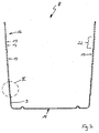
- Fig. 2 a cross section through the housing 9 of the catcher 8 is located in the side surfaces 12 of the housing 9 sectional plane.
- Fig. 3 shows an enlargement of the side wall 12 according to III in FIG Fig. 2 ,
- a plurality of venting slots is arranged, which are arranged parallel to the bottom 14 of the collecting basket 8 in rows.
- a plurality of parallel rows of ventilation slots 13 are arranged close to each other and the slot groups 22 thus formed are provided at intervals on the housing. This results in sections between the slot groups 22 with a continuous housing wall, which is advantageous for the strength of the housing.
- each vent slot is assigned a screen, at which the dirty air flow emerging through the slot is deflected in the direction of the floor.
- the screen bulges join the rim 14 of the vent slots 13 at the top 14 of the bottom and force the air flow downwards towards the lawn to be worked so that the dirty air is kept away from the operator disabling area.
- the wall 15 of the vent slots 13 forms a flow channel directed towards the bottom.
- the upper wall 15 with the respectively associated screen bead 20 forms a flat baffle surface for the air flow.
- the arrangement of the Schirmwülste at the upper edge 16 of the vent slots 13 and the slope of the Schirmwülste relative to the plane 18 of the housing wall 9 causes Schirmwülste at least partially cover the opening of the vent slots 13 with its free end, as illustrated by the projection line 19 with respect to the plane 18 is.
- the screen beads 20 on the surface of the side wall act as ribs and increase the strength of the housing.
- the screen beads are advantageously made in one piece with the side wall 9 and stand out about the same extent from the side wall 12, as the wall thickness b of the housing.
- the wall thickness b of the housing wall can be made smaller than was previously required, without the impression that the side wall is perceived as unpleasant.
- the cross-section Q of the screen beads 20 advantageously corresponds approximately to the height h of the ventilation slots.
- further screen beads 20 are provided in the sections 23 of the side wall 12, which are provided between the slot groups 22 in the housing.
- a further continuous screen bead is assigned below each of the bottom nearest slot row of a group 22 of multiple rows of slots, which is formed with the same inclination angle ⁇ as the other Schirmwülste 20 and ensures a harmonious appearance of the covered by Schirmwülste slot group.
Landscapes
- Life Sciences & Earth Sciences (AREA)
- Environmental Sciences (AREA)
- Harvester Elements (AREA)
Claims (10)
- Panier de ramassage pour une tondeuse à gazon roulante, qui est apte à être installé sur un carter (4) de la tondeuse (1) en vue de recueillir le produit coupé, un carter (9) du panier de ramassage (8) présentant au moins sur un côté (12) du panier (8) plusieurs fentes d'évacuation d'air (13), de sorte qu'un courant d'air sort dudit panier (8) sur le côté,
caractérisé en ce qu'il est prévu sur la surface du carter (9), dans la zone des fentes d'évacuation d'air (13), des renflements de protection (20) qui dépassent vers l'extérieur qui sont parallèles auxdites fentes (13) et qui forment par rapport à un plan (18) du carter (9) un angle en direction de la fente (13) voisine, et en ce que les renflements de protection (20) sont formés d'une seule pièce sur le carter (9) par une accumulation de matière, à la manière d'une nervure. - Panier de ramassage selon la revendication 1,
caractérisé en ce que les fentes d'évacuation d'air (13) sont disposées par séries et sont globalement parallèles à un fond (14) du panier de ramassage (8), et il est prévu pour chaque série de fentes un renflement de protection (20) sur un côté des fentes (13) opposé au fond (14), les renflements de protection (20) formant un angle en direction du fond (14). - Panier de ramassage selon la revendication 1 ou 2,
caractérisé en ce que chaque renflement de protection (20) fait suite à une partie d'un bord (16) de la fente (13) qui est opposée au fond (14) du panier. - Panier de ramassage selon la revendication 1, 2 ou 3,
caractérisé en ce que chaque fente d'évacuation d'air (13) est couverte au moins en partie par un renflement de protection (20), avec l'extrémité libre (21) de celui-ci. - Panier de ramassage selon l'une des revendications 1 à 4,
caractérisé en ce qu'une paroi (15) des fentes d'évacuation d'air (13) forme un canal (17) dirigé vers les renflements de protection (20). - Panier de ramassage selon la revendication 5,
caractérisé en ce que le renflement de protection (20) forme une surface avec la paroi (15) de la fente d'évacuation d'air (13). - Panier de ramassage selon l'une des revendications 1 à 6,
caractérisé en ce que les renflements de protection (20) dépassent du plan (18) du carter (9) sur une distance à peu près égale à l'épaisseur de paroi (b) dudit carter (9). - Panier de ramassage selon l'une des revendications 1 à 7,
caractérisé en ce qu'un angle d'inclinaison (α) des renflements de protection (20) par rapport au plan (18) du carter (9) est situé entre 20° et 80°, et est de préférence de 60° à 70°. - Panier de ramassage selon l'une des revendications 1 à 8,
caractérisé en ce que les renflements de protection (20) ont une forme constante. - Panier de ramassage selon l'une des revendications 1 à 9,
caractérisé en ce qu'une section transversale (Q) des renflements de protection (20) présente à peu près la même valeur que la hauteur (h) des fentes d'évacuation d'air (13).
Applications Claiming Priority (1)
| Application Number | Priority Date | Filing Date | Title |
|---|---|---|---|
| DE200420014554 DE202004014554U1 (de) | 2004-09-16 | 2004-09-16 | Fangkorb für einen Rasenmäher |
Publications (3)
| Publication Number | Publication Date |
|---|---|
| EP1637029A1 EP1637029A1 (fr) | 2006-03-22 |
| EP1637029B1 EP1637029B1 (fr) | 2010-10-06 |
| EP1637029B2 true EP1637029B2 (fr) | 2017-07-05 |
Family
ID=33483633
Family Applications (1)
| Application Number | Title | Priority Date | Filing Date |
|---|---|---|---|
| EP05017455.6A Expired - Lifetime EP1637029B2 (fr) | 2004-09-16 | 2005-08-11 | Dispositif de ramassage de gazon pour une tondeuse à gazon |
Country Status (3)
| Country | Link |
|---|---|
| EP (1) | EP1637029B2 (fr) |
| DE (2) | DE202004014554U1 (fr) |
| ES (1) | ES2353229T5 (fr) |
Citations (7)
| Publication number | Priority date | Publication date | Assignee | Title |
|---|---|---|---|---|
| US3191370A (en) † | 1964-06-05 | 1965-06-29 | G W Davis Corp | Grass collector for a lawnmower |
| US3398514A (en) † | 1966-04-28 | 1968-08-27 | Frank N. Nolan | Power mower with grass catcher |
| US3517493A (en) † | 1968-04-08 | 1970-06-30 | Turner Ind Ltd | Lawnmower and grass catcher therefor |
| GB1206705A (en) † | 1968-11-19 | 1970-09-30 | G D Mountfield Ltd | Improvements in rotary mowers or grass cutters |
| US4087955A (en) † | 1975-08-21 | 1978-05-09 | Canadian General Electric Company Limited | Rotary lawn mower with improved grass collector |
| US4244164A (en) † | 1978-07-07 | 1981-01-13 | Canadian General Electric Company Limited | Safety lawn mower and grass collector |
| EP0610062A1 (fr) † | 1993-02-01 | 1994-08-10 | Electrolux Outdoor Products Limited | Dispositif collecteur |
Family Cites Families (4)
| Publication number | Priority date | Publication date | Assignee | Title |
|---|---|---|---|---|
| DE6902002U (de) * | 1969-01-20 | 1969-05-29 | Zuendapp Werke Gmbh | Rasenmaeher mit grasauffangvorrichtung |
| SE394934B (sv) * | 1974-06-26 | 1977-07-25 | Stiga Ab | Anordning vid gresutkastoppningen hos motordriven gresklippningsmaskin |
| US3969876A (en) * | 1975-04-18 | 1976-07-20 | Mtd Products Inc. | Combination mower and catcher |
| DE2811192A1 (de) * | 1978-03-15 | 1979-10-04 | Assche Viktor Maria Van | Grasfangkorb fuer sichelrasenmaeher mit geeigneter entlueftung zwecks vollstaendiger auffuellung von geschnittenem gras |
-
2004
- 2004-09-16 DE DE200420014554 patent/DE202004014554U1/de not_active Expired - Lifetime
-
2005
- 2005-08-11 ES ES05017455.6T patent/ES2353229T5/es not_active Expired - Lifetime
- 2005-08-11 EP EP05017455.6A patent/EP1637029B2/fr not_active Expired - Lifetime
- 2005-08-11 DE DE200550010332 patent/DE502005010332D1/de not_active Expired - Lifetime
Patent Citations (7)
| Publication number | Priority date | Publication date | Assignee | Title |
|---|---|---|---|---|
| US3191370A (en) † | 1964-06-05 | 1965-06-29 | G W Davis Corp | Grass collector for a lawnmower |
| US3398514A (en) † | 1966-04-28 | 1968-08-27 | Frank N. Nolan | Power mower with grass catcher |
| US3517493A (en) † | 1968-04-08 | 1970-06-30 | Turner Ind Ltd | Lawnmower and grass catcher therefor |
| GB1206705A (en) † | 1968-11-19 | 1970-09-30 | G D Mountfield Ltd | Improvements in rotary mowers or grass cutters |
| US4087955A (en) † | 1975-08-21 | 1978-05-09 | Canadian General Electric Company Limited | Rotary lawn mower with improved grass collector |
| US4244164A (en) † | 1978-07-07 | 1981-01-13 | Canadian General Electric Company Limited | Safety lawn mower and grass collector |
| EP0610062A1 (fr) † | 1993-02-01 | 1994-08-10 | Electrolux Outdoor Products Limited | Dispositif collecteur |
Also Published As
| Publication number | Publication date |
|---|---|
| EP1637029A1 (fr) | 2006-03-22 |
| ES2353229T3 (es) | 2011-02-28 |
| DE502005010332D1 (de) | 2010-11-18 |
| ES2353229T5 (es) | 2017-11-16 |
| EP1637029B1 (fr) | 2010-10-06 |
| DE202004014554U1 (de) | 2004-11-18 |
Similar Documents
| Publication | Publication Date | Title |
|---|---|---|
| DE3542276C2 (fr) | ||
| DE2830052C2 (de) | Rasenmäher | |
| EP0079399B1 (fr) | Dispositif de nettoyage pour nettoyer le filtre à air d'un carter d'air de refroidissement avec un radiateur comprenant un ventilateur | |
| DE2459899C2 (fr) | ||
| DE2926725A1 (de) | Kuehlluftfilter fuer den brennkraftmotor, insbesondere fuer selbstfahrende landwirtschaftliche maschinen | |
| DE4035854C2 (de) | Vorrichtung zum Fangen und Ableiten des von einem Fahrzeugrad hochgeschleuderten Spritzwassers | |
| US12052947B2 (en) | Lawn mower provided with a divider plate dividing an enclosed space into an upper space and a cutting space | |
| EP2258160B1 (fr) | Capot moteur d'une moissonneuse batteuse | |
| EP0072572A1 (fr) | Réservoir collecteur d'une tondeuse à gazon | |
| EP1725154A1 (fr) | Accessoire de nettoyage par aspiration con u pour un aspirateur | |
| DE60210169T2 (de) | Mähwerk und Fahrzeug zur Rasen-, Garten- und Grundstückspflege | |
| EP1275285B1 (fr) | Dispositif de coupe et véhicule pour l'entretien de gazon et jardin | |
| DE19525247B4 (de) | Schutzeinrichtung für einen Rasenrandschneider | |
| DE3815321C2 (de) | Staubsauger | |
| DE20021378U1 (de) | Erntemaschine mit seitlichen Zugangsöffnungen und Abdeckplatten | |
| EP1637029B2 (fr) | Dispositif de ramassage de gazon pour une tondeuse à gazon | |
| DE2429467B2 (de) | Schmutzfängerlappen für Kraftfahrzeuge | |
| EP2952819B1 (fr) | Système de filtre pour hotte aspirante et hotte aspirante | |
| EP0254657B1 (fr) | Tondeuse à gazon munie d'un siège pour conducteur | |
| DE202005017238U1 (de) | Vorrichtung zur Säuberung, insbesondere zur Sandentfernung, von Grasflächen | |
| DE102019132186B4 (de) | Verschlussanordnung für einen rasenmäher, rasenmäher damit und konvertierbarer rasenmäher | |
| DE102006037453A1 (de) | Handgeführtes, motorgetriebenes Kehrgerät | |
| DE60216167T2 (de) | Sammelbehälter | |
| DE102010044301A1 (de) | Vertikutierer | |
| DE69719022T2 (de) | Vorrichtung zum Führen in einer Obsterntemaschine |
Legal Events
| Date | Code | Title | Description |
|---|---|---|---|
| PUAI | Public reference made under article 153(3) epc to a published international application that has entered the european phase |
Free format text: ORIGINAL CODE: 0009012 |
|
| AK | Designated contracting states |
Kind code of ref document: A1 Designated state(s): AT BE BG CH CY CZ DE DK EE ES FI FR GB GR HU IE IS IT LI LT LU LV MC NL PL PT RO SE SI SK TR |
|
| AX | Request for extension of the european patent |
Extension state: AL BA HR MK YU |
|
| 17P | Request for examination filed |
Effective date: 20060915 |
|
| AKX | Designation fees paid |
Designated state(s): BE DE ES FR IT |
|
| GRAP | Despatch of communication of intention to grant a patent |
Free format text: ORIGINAL CODE: EPIDOSNIGR1 |
|
| GRAS | Grant fee paid |
Free format text: ORIGINAL CODE: EPIDOSNIGR3 |
|
| GRAA | (expected) grant |
Free format text: ORIGINAL CODE: 0009210 |
|
| AK | Designated contracting states |
Kind code of ref document: B1 Designated state(s): BE DE ES FR IT |
|
| REF | Corresponds to: |
Ref document number: 502005010332 Country of ref document: DE Date of ref document: 20101118 Kind code of ref document: P |
|
| REG | Reference to a national code |
Ref country code: ES Ref legal event code: FG2A Effective date: 20110216 |
|
| PLBI | Opposition filed |
Free format text: ORIGINAL CODE: 0009260 |
|
| PLAX | Notice of opposition and request to file observation + time limit sent |
Free format text: ORIGINAL CODE: EPIDOSNOBS2 |
|
| 26 | Opposition filed |
Opponent name: HUSQVARNA AB Effective date: 20110706 |
|
| REG | Reference to a national code |
Ref country code: DE Ref legal event code: R026 Ref document number: 502005010332 Country of ref document: DE Effective date: 20110706 |
|
| PLAF | Information modified related to communication of a notice of opposition and request to file observations + time limit |
Free format text: ORIGINAL CODE: EPIDOSCOBS2 |
|
| PLBB | Reply of patent proprietor to notice(s) of opposition received |
Free format text: ORIGINAL CODE: EPIDOSNOBS3 |
|
| PLAB | Opposition data, opponent's data or that of the opponent's representative modified |
Free format text: ORIGINAL CODE: 0009299OPPO |
|
| R26 | Opposition filed (corrected) |
Opponent name: HUSQVARNA AB Effective date: 20110706 |
|
| APBM | Appeal reference recorded |
Free format text: ORIGINAL CODE: EPIDOSNREFNO |
|
| APBP | Date of receipt of notice of appeal recorded |
Free format text: ORIGINAL CODE: EPIDOSNNOA2O |
|
| APAH | Appeal reference modified |
Free format text: ORIGINAL CODE: EPIDOSCREFNO |
|
| APBQ | Date of receipt of statement of grounds of appeal recorded |
Free format text: ORIGINAL CODE: EPIDOSNNOA3O |
|
| REG | Reference to a national code |
Ref country code: FR Ref legal event code: PLFP Year of fee payment: 12 |
|
| APBU | Appeal procedure closed |
Free format text: ORIGINAL CODE: EPIDOSNNOA9O |
|
| PLBP | Opposition withdrawn |
Free format text: ORIGINAL CODE: 0009264 |
|
| PUAH | Patent maintained in amended form |
Free format text: ORIGINAL CODE: 0009272 |
|
| STAA | Information on the status of an ep patent application or granted ep patent |
Free format text: STATUS: PATENT MAINTAINED AS AMENDED |
|
| 27A | Patent maintained in amended form |
Effective date: 20170705 |
|
| AK | Designated contracting states |
Kind code of ref document: B2 Designated state(s): BE DE ES FR IT |
|
| REG | Reference to a national code |
Ref country code: DE Ref legal event code: R102 Ref document number: 502005010332 Country of ref document: DE |
|
| REG | Reference to a national code |
Ref country code: FR Ref legal event code: PLFP Year of fee payment: 13 |
|
| REG | Reference to a national code |
Ref country code: ES Ref legal event code: DC2A Ref document number: 2353229 Country of ref document: ES Kind code of ref document: T5 Effective date: 20171116 |
|
| REG | Reference to a national code |
Ref country code: FR Ref legal event code: PLFP Year of fee payment: 14 |
|
| REG | Reference to a national code |
Ref country code: DE Ref legal event code: R082 Ref document number: 502005010332 Country of ref document: DE Representative=s name: PATENTANWAELTE DIPL.-ING. W. JACKISCH & PARTNE, DE Ref country code: DE Ref legal event code: R082 Ref document number: 502005010332 Country of ref document: DE Representative=s name: PATENTANWAELTE DIPL.-ING. WALTER JACKISCH & PA, DE Ref country code: DE Ref legal event code: R081 Ref document number: 502005010332 Country of ref document: DE Owner name: ANDREAS STIHL AG & CO. KG, DE Free format text: FORMER OWNER: VIKING GMBH, LANGKAMPFEN, AT |
|
| REG | Reference to a national code |
Ref country code: ES Ref legal event code: PC2A Owner name: ANDREAS STIHL AG & CO. KG Effective date: 20181008 |
|
| REG | Reference to a national code |
Ref country code: BE Ref legal event code: PD Owner name: ANDREAS STIHL AG & CO. KG; DE Free format text: DETAILS ASSIGNMENT: CHANGE OF OWNER(S), CESSION; FORMER OWNER NAME: VIKING GMBH Effective date: 20181009 |
|
| P01 | Opt-out of the competence of the unified patent court (upc) registered |
Effective date: 20230518 |
|
| PGFP | Annual fee paid to national office [announced via postgrant information from national office to epo] |
Ref country code: IT Payment date: 20230822 Year of fee payment: 19 Ref country code: ES Payment date: 20230914 Year of fee payment: 19 |
|
| PGFP | Annual fee paid to national office [announced via postgrant information from national office to epo] |
Ref country code: DE Payment date: 20240828 Year of fee payment: 20 |
|
| PGFP | Annual fee paid to national office [announced via postgrant information from national office to epo] |
Ref country code: BE Payment date: 20240826 Year of fee payment: 20 |
|
| PGFP | Annual fee paid to national office [announced via postgrant information from national office to epo] |
Ref country code: FR Payment date: 20240826 Year of fee payment: 20 |
|
| PG25 | Lapsed in a contracting state [announced via postgrant information from national office to epo] |
Ref country code: IT Free format text: LAPSE BECAUSE OF NON-PAYMENT OF DUE FEES Effective date: 20240811 |
|
| REG | Reference to a national code |
Ref country code: DE Ref legal event code: R071 Ref document number: 502005010332 Country of ref document: DE |
|
| REG | Reference to a national code |
Ref country code: ES Ref legal event code: FD2A Effective date: 20250929 |
|
| PG25 | Lapsed in a contracting state [announced via postgrant information from national office to epo] |
Ref country code: ES Free format text: LAPSE BECAUSE OF NON-PAYMENT OF DUE FEES Effective date: 20240812 |
|
| REG | Reference to a national code |
Ref country code: BE Ref legal event code: MK Effective date: 20250811 |