EP1637653A2 - Dispositif de passage à niveau de voies ferrées - Google Patents
Dispositif de passage à niveau de voies ferrées Download PDFInfo
- Publication number
- EP1637653A2 EP1637653A2 EP05018064A EP05018064A EP1637653A2 EP 1637653 A2 EP1637653 A2 EP 1637653A2 EP 05018064 A EP05018064 A EP 05018064A EP 05018064 A EP05018064 A EP 05018064A EP 1637653 A2 EP1637653 A2 EP 1637653A2
- Authority
- EP
- European Patent Office
- Prior art keywords
- track
- support
- transition
- transition plates
- support structure
- Prior art date
- Legal status (The legal status is an assumption and is not a legal conclusion. Google has not performed a legal analysis and makes no representation as to the accuracy of the status listed.)
- Granted
Links
- 230000007704 transition Effects 0.000 claims abstract description 264
- 239000000463 material Substances 0.000 claims description 23
- 230000015572 biosynthetic process Effects 0.000 claims description 15
- 239000004567 concrete Substances 0.000 claims description 12
- 229920001971 elastomer Polymers 0.000 claims description 7
- 239000002131 composite material Substances 0.000 claims description 6
- 239000000758 substrate Substances 0.000 claims description 6
- 238000010292 electrical insulation Methods 0.000 claims description 5
- 239000008187 granular material Substances 0.000 claims description 4
- 230000001419 dependent effect Effects 0.000 claims 2
- 230000001052 transient effect Effects 0.000 claims 1
- 238000004873 anchoring Methods 0.000 description 12
- 238000005755 formation reaction Methods 0.000 description 11
- 230000008878 coupling Effects 0.000 description 9
- 238000010168 coupling process Methods 0.000 description 9
- 238000005859 coupling reaction Methods 0.000 description 9
- 239000004575 stone Substances 0.000 description 9
- 238000006073 displacement reaction Methods 0.000 description 8
- 238000010276 construction Methods 0.000 description 5
- 238000013461 design Methods 0.000 description 4
- 238000009434 installation Methods 0.000 description 4
- 238000004519 manufacturing process Methods 0.000 description 4
- 239000007769 metal material Substances 0.000 description 4
- 229910052782 aluminium Inorganic materials 0.000 description 3
- XAGFODPZIPBFFR-UHFFFAOYSA-N aluminium Chemical compound [Al] XAGFODPZIPBFFR-UHFFFAOYSA-N 0.000 description 3
- 238000005266 casting Methods 0.000 description 3
- 238000007493 shaping process Methods 0.000 description 3
- 238000003466 welding Methods 0.000 description 3
- 229910000831 Steel Inorganic materials 0.000 description 2
- 238000004026 adhesive bonding Methods 0.000 description 2
- 239000011230 binding agent Substances 0.000 description 2
- 238000009413 insulation Methods 0.000 description 2
- 230000004048 modification Effects 0.000 description 2
- 238000012986 modification Methods 0.000 description 2
- 239000007787 solid Substances 0.000 description 2
- 239000010959 steel Substances 0.000 description 2
- 238000009825 accumulation Methods 0.000 description 1
- 230000009471 action Effects 0.000 description 1
- 239000000853 adhesive Substances 0.000 description 1
- 230000001070 adhesive effect Effects 0.000 description 1
- 239000011449 brick Substances 0.000 description 1
- 239000000969 carrier Substances 0.000 description 1
- 239000000835 fiber Substances 0.000 description 1
- 230000003993 interaction Effects 0.000 description 1
- 238000002955 isolation Methods 0.000 description 1
- 238000012423 maintenance Methods 0.000 description 1
- 238000000034 method Methods 0.000 description 1
- 239000004570 mortar (masonry) Substances 0.000 description 1
- 229920002635 polyurethane Polymers 0.000 description 1
- 239000004814 polyurethane Substances 0.000 description 1
- 230000008569 process Effects 0.000 description 1
- 238000012958 reprocessing Methods 0.000 description 1
- 238000005488 sandblasting Methods 0.000 description 1
- 238000003860 storage Methods 0.000 description 1
- 238000012546 transfer Methods 0.000 description 1
- 239000002023 wood Substances 0.000 description 1
Images







Classifications
-
- E—FIXED CONSTRUCTIONS
- E01—CONSTRUCTION OF ROADS, RAILWAYS, OR BRIDGES
- E01C—CONSTRUCTION OF, OR SURFACES FOR, ROADS, SPORTS GROUNDS, OR THE LIKE; MACHINES OR AUXILIARY TOOLS FOR CONSTRUCTION OR REPAIR
- E01C9/00—Special pavings; Pavings for special parts of roads or airfields
- E01C9/04—Pavings for railroad level-crossings
Definitions
- the present invention relates to a track transition device.
- a track transition device in which lie between the two rails of a track system and each outside the rails groups of track transition plates.
- Each of these groups includes a plurality of plates successive in a longitudinal direction of the track transition means.
- These individual plates or groups of plates are combined into a composite by coupling rods extending in the longitudinal direction of the track transition device through these plates or on their underside and are also locked relative to the substrate in the longitudinal direction of the track transition device.
- the individual transition plates of these groups are constructed of rubber or rubber-containing material. In particular, used here is scrap rubber granules, for example obtained from the reprocessing of vehicle tires. The individual granules are firmly bound together by a binder.
- a track transition device comprising at least a first group of successive in a longitudinal direction of the track transition device support structure transition plates and a second group of in the longitudinal direction of the track transition device successive, carried on the support structure transition plates and a usable, in particular passable and / or walk-on deck-topped transition panels.
- the track transition device thus comprises two functionally cooperating groups of transition plates.
- the first group so the support structure transition plates, forms the substructure and provides for the second group, so the deck transition plates, the support structure.
- These deck transition plates are therefore no longer supported on the sleepers or any other surface, but lie on the transition plates of the first group.
- the deck transition plates of the second group with regard to their design and installation are independent of the location and the mutual distance of the thresholds of a track system. This is particularly noticeable in the curved area, where the mutual threshold distance in the outer area is greater than in the inner area of the curve.
- the uniform sized deck transition plates can be laid independently of such deviations in the threshold distance, and immediately adjacent to each other.
- Threshold distance variations can be intercepted around the transition plates of the first group.
- the deck transition plates need not be designed to accommodate and support the entire load exerted from above. This is primarily the function of the support structure transition plates, which can be optimized in terms of this Lastabstützfunktion.
- the deck transition plates may be laid substantially loosely on the supporting structural transition plates carrying them. That is, there is no need to provide a strong bond between these two groups of plates, such as by gluing, riveting or screwing.
- the second group of deck transition plates is anchored with respect to the first group of support structure transition plates carrying them. In this way, a bond between the two groups of plates is provided, which ensures that, especially when driving over obliquely with heavy vehicles, a relative displacement of the two groups with respect to each other can be avoided as far as possible.
- the deck transition plates held together by a in the longitudinal direction of the track transition device extending clamping element assembly into a composite are.
- the composite is anchored in at least one longitudinal end region of the second group with respect to a substrate.
- the clamping element arrangement be anchored with respect to at least one support structure transition plate.
- the support structure transition plates may be formed in a first end region for support on a rail and there may, in order to provide some flexibility or flexibility in the storage, a resilient support for support with respect to the rail.
- the support structure transition plates of the first group of metal material such as aluminum or steel material
- the support structure transition plates are electrically insulated in their first end region with respect to the rail and / or a rail fastening device , This can be provided in a very simple to implement embodiment in that the elastic support provides the electrical insulation.
- the support structure transition plates may be formed for support with respect to a transitional side boundary.
- a transitional side boundary can be formed, for example, by roadway boundary stones made of concrete material, to which the roadway leading to the track transition device then adjoins.
- At least one, preferably all support structure transition plates are supported in their second end region essentially transversely to the longitudinal direction of the track transition device by means of an adjustable transverse support arrangement .
- the adjustability of the transverse support arrangement ensures that even slight distance variations between the rails, on the one hand, and a transitional side boundary, on the other hand, can not lead to constraints or to oversized movement play.
- a very low-build but nevertheless stable construction in the area of the support structure transition plates may provide that the support structure transition plates provide in their second end region a bearing surface for the deck transition plates, which is substantially flush with a in a central region of the support structure transition plates provided support surface.
- At least one, preferably all support structure transition plates in the longitudinal direction of the track transition means have an extension which is shorter than the average threshold distance of a track system on which the track transition device is provided.
- This has the consequence that at least in different areas between the individual directly adjacent support structure transition plates intermediate spaces are formed. These gaps may be larger where support structure transition plates are in an outboard region, and may be smaller where support structure transition plates lie in a bend interior region.
- the presence of such spaces is not a problem as they will be covered by deck transition plates.
- due to the fact that these spaces are comparatively small and can be in the range of a few centimeters, there is no risk that under load the deck transition plates can dodge down.
- At least one of the deck transition panels may be made using rubber granules, preferably Altgummigranulat be constructed.
- the or at least one of the support structure transition plates can be constructed with hollow profile material, so for example made of aluminum hollow profile beams.
- Unwanted lifting of the deck transition plates from the support structure transition plates, in particular when driving over faster trains can be prevented by having the deck transition plates in a near-rail to be positioned end portion and / or a rail remote end to be positioned form-fitting engagement formation for positive engagement in the vertical direction with a rail or a transitional side boundary.
- the present invention relates to a transverse support arrangement for supporting a transition plate at a transitional side boundary substantially transverse to a longitudinal direction of a track transition device, in particular a track transition device according to the invention, comprising a first support portion at the transition side boundary and a second support portion at one A transition plate, wherein the first support portion and the second support portion in a height direction wedge to each other to form a height-tapered gap, further comprising a support member which is supported on the first support portion and the second support portion and having a support portion of the first support portion and second support area in different height positions and height direction is immovably coupled or coupled.
- the support element has a first gear formation and the one support portion standing with the first gear formation in coupling engagement or bringable having second Vernierungsformation.
- the one support region can be, for example, the second support region.
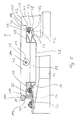
- a track transition device according to the invention is generally designated 10.
- This track transition device 10 is shown in conjunction with a track system 12, which includes a plurality of in a longitudinal direction L of the track system 12 and the track transition device 10 consecutively arranged thresholds 14 in a conventional construction.
- the rails 16, 18 are supported on these sleepers 14 at a lateral distance, the rails 16, 18 being fixed to the sleepers 14 via so-called individual supports 20, respectively.
- the thresholds 14 may be embedded in a ballast bed, but may for example be cast in a track system 12 of the type slab track in a concrete layer over which they can survive with their upper portion.
- the side of the track system 12 is in the area in which the track transition device 10 is provided and thus a roadway, a walkway o. The like.
- a transition side boundary 22 is provided. This generally comprises a plurality of delimiting stones 24, arranged consecutively in the longitudinal direction L, whose outline will be discussed below and which are generally made of concrete material. At this Fahrbahnbegrenzungssteine 24 then adjoins, for example, a paved roadway.
- the track transition device 10 represents in that shown in Figs. 1 and 2 Example, a transition region between the road, so the transition side boundary 22, and the rail 18 ago. It goes without saying that a corresponding arrangement can also be provided on the other side of the track system 12, that is to say between the rail 16 and the roadway adjacent thereto, as well as between the rails 16 and 18.
- the track transition device 10 comprises two groups of transition plates.
- a first group 26 provides support structure transition plates 28.
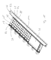
- a plurality of these support structure transition plates 28 are arranged successively in the longitudinal direction L, so that they extend between the rail 18 and the transition side boundary 22, ie the bricks 24.
- Each of these support structure transition plates 28 is located in a first end portion 30 on the rail 18, namely the rail foot 32 thereof, namely, as is also clearly visible in Fig. 5, via an elastic support element 34.
- This is on a as Hollow profile part designed support member 36 by bonding, by introduction into corresponding profile recesses o. The like. Worn and thus fixed.
- the contour of the carrier element 36 in the adjoining area to the rail 18 or the rail foot 32 thereof is adapted to the shape of the rail 18 in this area.
- a further designed as a hollow profile part support member 38 is provided, which, as well as the support member 36, is elongated in the longitudinal direction L and now with respect to the transition side boundary 22, so the stones 24, supported.
- the support here takes place on an approximately horizontally extending but slightly inclined leg region 42 of the transitional lateral boundary 22, in each case via an elastic support element 44, which is likewise held on the carrier element 38 by appropriate positive engagement.
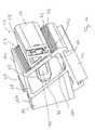
- the supporting structure transition plates 28 are supported in each case via a transverse support arrangement 46, which can be clearly seen in FIGS. 6 and 7.
- This cross-support assembly 46 includes a first support portion 48 at the transitional side boundary 22, in the form of an approximately vertical, but slightly outwardly and upwardly inclined leg 50 thereof.
- a second support portion 52 is formed on each of the support structure transition plates 28 on the support member 38.
- This second support region 52 also includes an approximately vertical, but now slightly upwards and inwards, ie in the direction of the rail 18, inclined side region 54.
- the two support regions 48, 52 are positioned wedge-like in the installed state of the support structure transition plate 28 so that they include a downwardly wedge-like tapered space 56 between them.
- each support structure transition element 28 is further arranged in this space 56 or to be positioned support member 58 is provided.
- this support element 58 has a further elastic support element 60, which is supported directly on the first support region 48, that is to say an opposite one of the stones 24.
- a body part 62 of the support element 58 which is also produced, for example, as a hollow profile part, is further supported on the second support region 52, that is to say on the side 54 of the support element 38.
- each toothing formations 64, 66 are provided, which are elongated in the longitudinal direction L and transverse to the longitudinal direction L, that is approximately in the height direction, a plurality of tooth projections or depressions sequentially.
- the support member 58 can be arranged on the side 54 of the support member 38 in different positions, in which arrangement then the two gear formations 64 and 66 are brought into mutual engagement. Once this intervention is made, a displacement of the support element 58 in the height direction with respect to the support member 38 is practically no longer possible.
- one or more locking elements 68 are provided to define a support element 58 in a selected positioning on the carrier element 38. These can be through Slot-like recesses 70 and of course correspondingly positioned interruptions 72 are inserted into the support element 60 in slot-like recesses 74 in the side 54 of the support member 38, wherein in the fully inserted positioning, which is shown in Fig.
- one on the or each locking element 68 provided latching tab 76, the side 54 and the support member 38 engages over and thus secures the locking member 68 against undressing.
- latching tab 76 can be intervened laterally in the designed as a hollow profile member support member 38 either with a hand or a tool and the locking tab 76 are pushed into alignment with the remaining portion of the locking member 68, so that this then from his in Fig. 6 shown positioning can be pulled out and thus the locking of the support member 58 can be solved on an associated support structure transition plate 28.
- Each of the support structure transition plates 28 further comprises between the support members 36, 38, with which the support or support with respect to the rail 18 and the transition side boundary 22 takes place, two further support members 78, 80. These extend between the two support members 36, 38th and are firmly connected to these, for example, by welding, riveting, gluing or in any other way.
- the two substantially transversely to the longitudinal direction L elongated support members 78, 80 carry between them in the example shown two bridging elements 82, 84, thus bridging the gap between the two support members 36, 38 on the one hand and the support members 78, 80 on the other.
- each support structure transition plate 28 forms a Schwellenabilityaussparung 86. That is, the support members 78, 80 engage with their viewed in the height direction lower portions each in Thresholds 88 formed between two thresholds 14.
- the space available in the height direction space is used in an optimal manner and nevertheless due to the ability to use solid structural support members 78, 80, achieved a high carrying capacity in the support structure transition plates.
- the support structure transition plates 28 are not based directly on the thresholds 14 and not on the material surrounding the thresholds 14, so for example gravel material from, but bridge the area between the rail 18 and the transition side boundary 22.
- the installation position of the support structure- Transition plates 28 completely independent of the shape of the thresholds and continue to be completely independent from the shaping or accumulation of the material surrounding the sills 14.
- these have in association with each rail 18 defining individual support point 20 in the support member 36 a recognizable in FIG.
- the recess 90 is dimensioned in particular in the longitudinal direction L such that even slight displacements of a support structure transition plate 28 in this longitudinal direction L can not lead to contact between the support element 36 and the individual support point 20.
- care must nevertheless be taken to avoid electrically conductive contact between the support structure transition plate 28 and the single support 20, as well as the rail 18 provided in the region of the recess 90 for electrical insulation.
- the elastic support element 34 otherwise producing the electrical insulation between the carrier element 36 and the rail 18 being integrally formed with an insulation region comprising, for example, a plurality of insulating lugs, which engage in the recess 90 and which will engage when a support structure transition plate 28 is placed on the rail 18 surrounds the recess 90 engaging portion of the single support point 20 and thus also insulated with respect to the support member 36, even if excessive displacement should occur.
- this isolation region can be provided with slot-like openings in order to be able to reach through with a tool.
- the dimensioning of the support structure transition plates 28 in the longitudinal direction L of the track transition device 10 is such that there is a slight between directly adjoining support structure transition plates 28 Gap 92 is created in the range of 2 to 4cm.
- Each of these support structure transition plates 28 is set more or less in a limited space with respect to their position in the longitudinal direction L, namely determined by the fact that the area of the respective threshold 14 lying outside the rail 18 must be accommodated in the threshold receiving recess 86.
- the length of the support structure transition plates 28 in the longitudinal direction L is therefore not necessarily exactly equal to the pitch of the thresholds 14, ie the threshold distance.
- a second group 94 is provided. This includes a plurality of deck transition plates 96. Also, the deck transition plates 96 are successively positioned in the longitudinal direction L, so that in the longitudinal direction L over the entire length of the track transition device 10 results in a substantially closed surface. However, now the deck transition plates 96 abut each other directly. It should be emphasized here that in Figs. 1 and 2 between the two illustrated deck transition plates 96, another deck transition plate is to be positioned, but omitted for the sake of clarity of drawing. The division of the deck transition plates 96 in the longitudinal direction L is independent of the pitch of the support structure transition plates 28. The small gaps formed between the individual support structure transition plates 28 do not affect the load capacity.
- the deck transition plates 96 of the second group 94 are constructed of elastic or flexible material.
- Altgummigranulat has been particularly suitable, which is baked by a binder, such as polyurethane using pressure and high temperature and thus results in very stable, especially the loads when driving exposed plates.
- a binder such as polyurethane using pressure and high temperature and thus results in very stable, especially the loads when driving exposed plates.
- These can, of course, be equipped on their surface 98 which is exposed for use upwards, with a structuring providing a desired grip.
- Fig. 5 it can be seen that in their the rail 18 to be positioned near end portion 100, these deck transition plates 96 are shaped so that they engage under a retaining projection 102, the rail head 104, so that they are firmly clamped there and also in the vertical direction are locked. In its end region 106 to be positioned near the transitional side boundary 22, the deck transition plates 96 are shaped such that they rest on the one hand on a further limb or a step 108 of the associated stones 24 and on the other hand on an approximately horizontally extending side surface region 110 in lateral Direction are supported and possibly rest there under bias. In Figs.
- the deck transition plates 96 are formed in its lower portion so that they are adapted to the overall contour of the support structure transition plates 28 and in particular in the between the two support members 36, 38 and over engage the carrier elements 78, 80 and the bridging elements 82, 84 formed space.
- the cover transition plates 96 are thus substantially over the entire surface on the support structure transition plates 28 and are also locked by this adapted shaping transverse to the longitudinal direction L with respect to the support structure transition plates 28.
- a clamping element assembly 112 is provided. This extends in the longitudinal direction L along the cover transition plates 96 and passes through an opening provided in each of these.
- the clamping element arrangement 112 can comprise a plurality of clamping rods 114, the length of these clamping rods 114 being matched to the length of the cover transition plates 96 in the longitudinal direction L, so that in each case such a clamping rod 114 a cover transition plate 96 to an immediately following cover Transition plate 96 or the tension rod 114 passing through this binds.
- a connection to the substrate can then also be made, for example, via the clamping element arrangement 112.
- mounting bracket o. The like. Come used.
- the clamping element assembly 112 may include a plurality of such groups of tie rods 114 side by side.
- the deck transition plates 96 of the second group 94 essentially serve to provide the surface with the desired surface properties, ie elasticity properties and suitable coefficients of friction. However, they do not have to be dimensioned and configured so that they also carry the entire load and support it to the ground. This is the task of the support structure transition plates, which can be configured on the one hand from suitable materials and on the other hand with a suitable shape, but here must not be paid to certain surface properties. It is therefore of course also possible, the support structure transition plates 28 is not composed of a plurality of hollow profile carriers, for example made of aluminum, but to provide them as integral castings, such as concrete castings, which can of course also be reinforced according to the existing requirements.
- the transverse support at the transitional side boundary 22 can take place via the transverse support arrangement 46 described in detail above with reference to FIGS. 6 and 7.
- the toothing formation 64 can be molded with.
- such a transverse support arrangement can be used even if, for example, made of concrete material transition plates alone, so without a further cover layer, to be used and also provide the usable surface should.
- the track transition device 10 according to the invention, as already mentioned, not only in the lateral abutment areas, ie where a roadway to the track system 12 reaches, can be used, but that such a structure in the between the two rails 16, 18 lying range can be selected, although here are the above-mentioned problems with respect to the load less serious.
- FIGS. 8 and 9 show a modified embodiment of a track transition device 10 according to the invention. This agrees in essential aspects with those described above, so that the essential differences are discussed below. It can be seen first of all, in particular in FIG. 9, that a difference is present above all in the design of the carrier element 38 to be positioned far away from the rail. While in the embodiment described above this support member 36, together with the rail member 36 to be positioned near the rail, forms an upwardly open recessed area which provides with the surfaces of the support members 78, 80 and the bridging members 82, 84 the substantial total support surface supporting the deck transition plates 96 in the embodiment shown in FIGS.
- the carrier element 38 is designed so that it does not essentially project beyond the support surface 150 provided by the carrier elements 78, 80 and the bridging elements 82, 83, 84 and a contact surface 152 terminating flush with the latter provides. That is, a step-like transition is provided here only at the rail-near end region by the support member 36. With its end region 106 to be positioned far away from the rail, a cover transition plate 96 extends beyond the flush adjoining support surfaces 150, 152 to the outside, where it then bears against the transitional side boundary 22 with the side surface region 110.
- the transitional side boundary 22 In this area of mutual abutment has the transitional side boundary 22 and a respective one Stone 24 of the same a groove-like and in the rail longitudinal direction L extending recess 154 into which an outwardly engaging retaining projection 156 of a cover transition plate 96 can engage.
- the deck transition plates 96 are both held in its near-rail end portion 100 and in their rail remote end portion 106 in the vertical direction by positive engagement, namely with respect to the rail 18 on the one hand and with respect to the transition side boundary 22 on the other.
- the shape of the transitional side boundary 22 could be as described above with reference to FIGS. 1 to 7, so that here no form-fitting engagement is present in the end region remote from the rail.
- this form-fitting engagement is present only in the rail-distant end region of the cover transition plates 96, while it is not present in the end region near the rail. Even if such a positive engagement in height direction is effective in both end regions, this can be easily realized in the construction of a track transition device 10, that the generally elastically deformable deck transition plates are first deformed using appropriate tools during installation, so that they then engage under locking action in the undercuts or depressions.
- FIGS. 8 and 9 Another difference in this embodiment shown in FIGS. 8 and 9 to the embodiment described above in the connection of the support members 36, 78 and 80.
- the support member 36 is now a partial section the upwardly exposed surface of the carrier elements 78, 80 extends away and in the formed in this area abutment edge regions 158 is welded to this substantially transverse to the rail longitudinal direction L, that has in this direction extending welds.
- a support member 78, 80 at its rail near end portions downwardly over or extending along the same extending connecting portion 160 is provided, the is also welded in its approximately downwardly running edge or edge regions 162 with the support members 78, 80.
- Another weld 164 is formed extending the lower end portion of this portion 160 in the longitudinal direction L.
- FIGS. 10 and 11 A modification of the embodiment shown in FIGS. 8 and 9 can be seen in FIGS. 10 and 11.
- this comprises a plurality of stones 24 formed of concrete material, are now made of metal material, such as steel, elongated in the longitudinal direction L side boundary elements 170 are provided.
- metal material such as steel
- L side boundary elements 170 are provided. These are designed, for example, by welding a plurality of shaped plate elements so that they correspond in their cross-sectional contour approximately to the previously also recognizable contour of the stones 24 formed of concrete material. That is, basically, the same functionality as described above can be obtained, but with construction of these metal material elements.
- the side boundary elements 170 can be fixed by using a quick-setting mortar or adhesive material on a prepared substrate, such as concrete substrate. Again, it should be noted that the side boundary members 170 may of course also have the groove-like recess 154, as has been previously described.
- FIGS. 8 to 11 can also be designed in particular with regard to the support with respect to the respective rail 16 or 18, as the embodiment shown in FIGS. 1 to 7. That is, in particular, the elastic support member 34 may not only provide an elastic support and thus also an insulation with respect to the respective rail 16 and 18, but may also with appropriate shaped sections a possibly required electrical insulation between the support member 36 and the respective engaging in this region of a single support point 20 provide.
- those surfaces or surface areas of the support structure transition plates 28, on which deck transition plates 96 rest, for example, by sandblasting can be roughened to here an improved frictional engagement between the deck transition plates 96th and to realize the support structure transition plates 28 and thus counteract a possibly occurring by oblique force when driving over shift of the deck transition plates 96 in the longitudinal direction L.
- FIGS. 12 and 13 Another way to counteract this shift is described below with reference to FIGS. 12 and 13.
- a support structure transition plate 28 of the embodiment shown in Figs. 8-11 is shown in Fig. 12, an anchor assembly 172 shown there may of course also be used in the support structure transition plates 28 shown in Figs. 1-7.
- the anchoring arrangement 172 comprises a plate-like anchoring element 174, which is formed essentially in the manner of a clamp, ie with a U-shaped cross section, and thus the plate-like bridging element 83 which lies between the two detectable bridging elements 82, 84 , overlaps and held on this.
- the extension length of the anchoring element 174 is selected so that it corresponds to the extension length of the bridging element 83 between the two support elements 78, 80, so that the anchoring element 174 between the support members 78, 80 in the longitudinal direction L, including the extension direction of the clamping element assembly 112th , practically can not move.
- a coupling element 176 which is formed in its two end regions with an internal thread in the longitudinal direction L, is fixed, for example by welding.
- this coupling element 176 two each configured with approximately half the length clamping rods 114 of the clamping element assembly 112 can be screwed, thus one over the support structure transition plate 28 shown in FIG. 12 positioned deck transition plate 96 fixed to the anchoring element 174 and thus the support structure transition plate 28 connect.
- This deck transition plate 96 is shown in FIG. It can be seen that this basically has the required for passing the tie rods 114, in the longitudinal direction L extending hole-like opening 178. In its central section, that is above the anchoring element 174 or the coupling element 176, this cover transition plate 96 has a downwardly open recess 180. This is so dimensioned that when positioning this deck transition plate 96 on the support structure transition plate 28 shown in Fig. 12, it receives over the support surface 150 extending beyond sections of the anchor assembly 172. In this way, otherwise, a full-surface bearing contact between the deck transition plate 96 of FIG. 3 and the support structure transition plate 28 of FIG. 12 is ensured.
- the cover transition plate 96 is positioned on the support structure transition plate 28. Then, of the two longitudinally located ends of the deck transition plate 96, the two tie rods 114 are passed through the respective section of the opening 178 located there and screwed with their threaded ends in the coupling element 76. Below can then be on both sides of the already established deck transition plate 96 more deck transition plates 96 are laid and then bolted to be passed through them with clamping rods 114 to the already existing and screwed into the coupling element 176 tie rods 114. This process can be continued in both directions until the desired number of deck transition plates 96 are laid.
- this anchoring arrangement 172 is preferably provided in a central region of a track transition device 10. In principle, it is also conceivable, for example, to provide a plurality of such anchoring arrangements 172 at longitudinally spaced apart positions in the case of longer track transition means 10.
- FIGS. 14 and 15 show a modified embodiment of a transverse support arrangement 46, as may be provided, for example, in association with the support structure transition plates 28 shown in FIGS. 8 to 11, but of course also in the case of the arrangement shown in FIGS. 1-7 shown embodiment can be used.
- the toothing formation 66 provided on the support element 58 has two spaced-apart groups 182 of teeth or ribs, wherein each of these groups 182 may, for example, comprise two teeth or ribs.
- the area between these two groups 182 is substantially flat and is not in engagement with the tooth formation 64 on the carrier element 38. In this way it is ensured that overestimating by too many interengaging projections or depressions is avoided even with minor manufacturing tolerances can be.
- a projection 184 is formed, which engages in an opening, not shown, of the support member 38 and in this way the elastic support member 44 secures against displacement with respect to the support member 38 . It is self-evident that a similar retaining formation which acts positively in the direction of displacement can also be provided in the elastic support element 34 of the support element 36, as well as in the support element 60, which is held on the support element 58 by form-fitting engagement.
- the clamping element arrangement 112 can be anchored with respect to at least one support structure transition plate 28.
- the various elastic support elements which can be secured against displacement with respect to these respectively receiving support elements or support elements by appropriate form-fitting engagement.
- the support structure transition plates 28 and deck transition plates 96 which are not made of concrete material, but from Metal material constructed transition side boundaries 22 are used.
Landscapes
- Architecture (AREA)
- Civil Engineering (AREA)
- Structural Engineering (AREA)
- Engineering & Computer Science (AREA)
- Road Paving Structures (AREA)
- Rod-Shaped Construction Members (AREA)
- Railway Tracks (AREA)
- Supports For Plants (AREA)
- Laying Of Electric Cables Or Lines Outside (AREA)
- Train Traffic Observation, Control, And Security (AREA)
- Machine Tool Units (AREA)
- Ropes Or Cables (AREA)
- Clamps And Clips (AREA)
- Mutual Connection Of Rods And Tubes (AREA)
- Peptides Or Proteins (AREA)
- Rehabilitation Tools (AREA)
- Types And Forms Of Lifts (AREA)
Priority Applications (4)
| Application Number | Priority Date | Filing Date | Title |
|---|---|---|---|
| SI200530995T SI1637653T1 (sl) | 2004-09-07 | 2005-08-19 | Prečna podporna razmestitev za tirno prehodno napravo |
| PL08000565T PL1914347T3 (pl) | 2004-09-07 | 2005-08-19 | Przejściowe pobocze toru |
| EP08000565A EP1914347B1 (fr) | 2004-09-07 | 2005-08-19 | Dispositif de passage à niveau de voies ferrées |
| PL05018064T PL1637653T3 (pl) | 2004-09-07 | 2005-08-19 | Układ poprzecznego podparcia dla przejściowego pobocza toru |
Applications Claiming Priority (1)
| Application Number | Priority Date | Filing Date | Title |
|---|---|---|---|
| DE102004043240A DE102004043240A1 (de) | 2004-09-07 | 2004-09-07 | Gleisübergangseinrichtung |
Related Child Applications (2)
| Application Number | Title | Priority Date | Filing Date |
|---|---|---|---|
| EP08000565A Division EP1914347B1 (fr) | 2004-09-07 | 2005-08-19 | Dispositif de passage à niveau de voies ferrées |
| EP08000565.5 Division-Into | 2008-01-14 |
Publications (3)
| Publication Number | Publication Date |
|---|---|
| EP1637653A2 true EP1637653A2 (fr) | 2006-03-22 |
| EP1637653A3 EP1637653A3 (fr) | 2007-04-25 |
| EP1637653B1 EP1637653B1 (fr) | 2010-02-24 |
Family
ID=35517965
Family Applications (2)
| Application Number | Title | Priority Date | Filing Date |
|---|---|---|---|
| EP08000565A Expired - Lifetime EP1914347B1 (fr) | 2004-09-07 | 2005-08-19 | Dispositif de passage à niveau de voies ferrées |
| EP05018064A Expired - Lifetime EP1637653B1 (fr) | 2004-09-07 | 2005-08-19 | Structure de support latérale pour dispositif de passage à niveau de voies ferrées |
Family Applications Before (1)
| Application Number | Title | Priority Date | Filing Date |
|---|---|---|---|
| EP08000565A Expired - Lifetime EP1914347B1 (fr) | 2004-09-07 | 2005-08-19 | Dispositif de passage à niveau de voies ferrées |
Country Status (7)
| Country | Link |
|---|---|
| EP (2) | EP1914347B1 (fr) |
| AT (2) | ATE458861T1 (fr) |
| DE (3) | DE102004043240A1 (fr) |
| DK (1) | DK1637653T3 (fr) |
| ES (2) | ES2339674T3 (fr) |
| PL (2) | PL1914347T3 (fr) |
| SI (1) | SI1637653T1 (fr) |
Cited By (6)
| Publication number | Priority date | Publication date | Assignee | Title |
|---|---|---|---|---|
| WO2007076981A1 (fr) | 2005-12-22 | 2007-07-12 | Gummiwerk Kraiburg Elastik Gmbh | Module en plaques et dispositif de traversee de voie dote d'un module en plaques |
| WO2012159596A1 (fr) * | 2011-05-26 | 2012-11-29 | Watermann Polyworks Gmbh | Bande isolante |
| FR2997423A1 (fr) * | 2012-10-31 | 2014-05-02 | Chapsol | Dispositif de passage a niveau ameliore |
| DE102014113295B3 (de) * | 2014-09-16 | 2016-02-11 | Railbeton Haas Kg | Bahnübergangsbelagssystem |
| HRP20120099B1 (hr) * | 2012-01-30 | 2017-06-02 | Slobodan Rajić | Gumeni željezničko-cestovni prijelaz |
| WO2017208036A1 (fr) * | 2016-05-28 | 2017-12-07 | Slobodan Rajic | Système pour relier des panneaux en caoutchouc pour un passage à niveau en caoutchouc |
Family Cites Families (5)
| Publication number | Priority date | Publication date | Assignee | Title |
|---|---|---|---|---|
| DE7113269U (de) * | 1971-04-06 | 1971-07-01 | Trelleborgs Gummifabriks Ab | Als Fahrbahndecke an Bahnübergängen zu verwendende Natur oder Kunstgummiplatte |
| CH580202A5 (fr) * | 1974-03-20 | 1976-09-30 | Semperit Ag | |
| US4266718A (en) * | 1978-07-27 | 1981-05-12 | True Temper Corporation | Modularized railway crossing grade and modules therefor |
| FR2556753B1 (fr) * | 1983-12-14 | 1986-07-25 | Carre Daniel | Platelage de passage a niveau |
| DE19623135A1 (de) * | 1996-06-10 | 1997-12-11 | Kraiburg Elastik | Vorrichtung zur Lagefixierung von Formkörpern einer Gleisübergangseinrichtung an einer Gleisanlage |
-
2004
- 2004-09-07 DE DE102004043240A patent/DE102004043240A1/de not_active Withdrawn
-
2005
- 2005-08-19 AT AT05018064T patent/ATE458861T1/de active
- 2005-08-19 ES ES05018064T patent/ES2339674T3/es not_active Expired - Lifetime
- 2005-08-19 SI SI200530995T patent/SI1637653T1/sl unknown
- 2005-08-19 PL PL08000565T patent/PL1914347T3/pl unknown
- 2005-08-19 DE DE502005009074T patent/DE502005009074D1/de not_active Expired - Lifetime
- 2005-08-19 DK DK05018064.5T patent/DK1637653T3/da active
- 2005-08-19 PL PL05018064T patent/PL1637653T3/pl unknown
- 2005-08-19 DE DE502005009162T patent/DE502005009162D1/de not_active Expired - Lifetime
- 2005-08-19 AT AT08000565T patent/ATE459757T1/de active
- 2005-08-19 EP EP08000565A patent/EP1914347B1/fr not_active Expired - Lifetime
- 2005-08-19 EP EP05018064A patent/EP1637653B1/fr not_active Expired - Lifetime
- 2005-08-19 ES ES08000565T patent/ES2341139T3/es not_active Expired - Lifetime
Cited By (6)
| Publication number | Priority date | Publication date | Assignee | Title |
|---|---|---|---|---|
| WO2007076981A1 (fr) | 2005-12-22 | 2007-07-12 | Gummiwerk Kraiburg Elastik Gmbh | Module en plaques et dispositif de traversee de voie dote d'un module en plaques |
| WO2012159596A1 (fr) * | 2011-05-26 | 2012-11-29 | Watermann Polyworks Gmbh | Bande isolante |
| HRP20120099B1 (hr) * | 2012-01-30 | 2017-06-02 | Slobodan Rajić | Gumeni željezničko-cestovni prijelaz |
| FR2997423A1 (fr) * | 2012-10-31 | 2014-05-02 | Chapsol | Dispositif de passage a niveau ameliore |
| DE102014113295B3 (de) * | 2014-09-16 | 2016-02-11 | Railbeton Haas Kg | Bahnübergangsbelagssystem |
| WO2017208036A1 (fr) * | 2016-05-28 | 2017-12-07 | Slobodan Rajic | Système pour relier des panneaux en caoutchouc pour un passage à niveau en caoutchouc |
Also Published As
| Publication number | Publication date |
|---|---|
| DK1637653T3 (da) | 2010-06-14 |
| PL1914347T3 (pl) | 2010-08-31 |
| DE102004043240A1 (de) | 2006-04-06 |
| EP1637653A3 (fr) | 2007-04-25 |
| EP1637653B1 (fr) | 2010-02-24 |
| EP1914347B1 (fr) | 2010-03-03 |
| ES2339674T3 (es) | 2010-05-24 |
| SI1637653T1 (sl) | 2010-07-30 |
| EP1914347A1 (fr) | 2008-04-23 |
| PL1637653T3 (pl) | 2010-07-30 |
| ATE459757T1 (de) | 2010-03-15 |
| ATE458861T1 (de) | 2010-03-15 |
| DE502005009162D1 (de) | 2010-04-15 |
| DE502005009074D1 (de) | 2010-04-08 |
| ES2341139T3 (es) | 2010-06-15 |
Similar Documents
| Publication | Publication Date | Title |
|---|---|---|
| EP2318589B1 (fr) | Dispositif pour fixer des rails de chemin de fer sur une sous-structure | |
| AT508847B1 (de) | Vorrichtung zur überbrückung einer dehnfuge | |
| DE2733011A1 (de) | Befestigungsvorrichtung fuer gleisschienen | |
| EP1956143B1 (fr) | Système d'habillage pour un rail, en particulier rail de tramway | |
| EP0377765B2 (fr) | Traverse en béton adaptable à deux écartements de voie | |
| DE202007019223U1 (de) | Verkehrsleitwand | |
| EP1386037A1 (fr) | Couverture de voie | |
| EP1637653B1 (fr) | Structure de support latérale pour dispositif de passage à niveau de voies ferrées | |
| DE10004194C2 (de) | Verfahren zur Fertigung einer festen Schienenfahrbahn auf einer Brücke | |
| EP1031668B1 (fr) | Elément de construction pour l'isolation thermique | |
| AT521653B1 (de) | Weichenanordnung mit elastisch gelagerten Weichentragplatten | |
| DE20220631U1 (de) | Fahrweg für spurgeführte Fahrzeuge | |
| EP1597434B1 (fr) | Piste pour trains a sustentation magnetique, et son procede de production | |
| EP0718438A1 (fr) | Superstructure de voie ferrée comprenant une dalle porteuse continue et des dispositifs de fixation individuels pour les rails | |
| DE10237176B4 (de) | Fahrbahn für Magnetbahnzüge | |
| EP2297401B1 (fr) | Voie sans ballast à appui continu | |
| EP3617404B1 (fr) | Rail de roulement et structure de voie dotée du rail de roulement | |
| EP1216326A1 (fr) | Procede pour construire une voie insonorisee | |
| EP2045394B1 (fr) | Zone de croisement de rails à gorge | |
| DE19517112A1 (de) | Gleisoberbau mit durchgehender Tragplatte und Einzel-Befestigungsvorrichtungen für die Schienen | |
| DE29917553U1 (de) | Gleisanlagen-Tragplatte, Gleisanlagen-Unterbau und Gleisanlage | |
| EP2800833B1 (fr) | Voie ferrée sans ballast | |
| AT511194B1 (de) | Vorrichtung zur überbrückung einer dehnungsfuge | |
| DE102009030535A1 (de) | Mehrteilige Schienenkammerfülleinrichtung | |
| EP1963577B1 (fr) | Module en plaques et dispositif de traversée de voie doté d'un module en plaques |
Legal Events
| Date | Code | Title | Description |
|---|---|---|---|
| PUAI | Public reference made under article 153(3) epc to a published international application that has entered the european phase |
Free format text: ORIGINAL CODE: 0009012 |
|
| AK | Designated contracting states |
Kind code of ref document: A2 Designated state(s): AT BE BG CH CY CZ DE DK EE ES FI FR GB GR HU IE IS IT LI LT LU LV MC NL PL PT RO SE SI SK TR |
|
| AX | Request for extension of the european patent |
Extension state: AL BA HR MK YU |
|
| PUAL | Search report despatched |
Free format text: ORIGINAL CODE: 0009013 |
|
| AK | Designated contracting states |
Kind code of ref document: A3 Designated state(s): AT BE BG CH CY CZ DE DK EE ES FI FR GB GR HU IE IS IT LI LT LU LV MC NL PL PT RO SE SI SK TR |
|
| AX | Request for extension of the european patent |
Extension state: AL BA HR MK YU |
|
| 17P | Request for examination filed |
Effective date: 20070904 |
|
| 17Q | First examination report despatched |
Effective date: 20071005 |
|
| AKX | Designation fees paid |
Designated state(s): AT BE BG CH CY CZ DE DK EE ES FI FR GB GR HU IE IS IT LI LT LU LV MC NL PL PT RO SE SI SK TR |
|
| GRAP | Despatch of communication of intention to grant a patent |
Free format text: ORIGINAL CODE: EPIDOSNIGR1 |
|
| RTI1 | Title (correction) |
Free format text: LATERAL SUPPORT STRUCTURE FOR LEVEL CROSSING DEVICE |
|
| GRAS | Grant fee paid |
Free format text: ORIGINAL CODE: EPIDOSNIGR3 |
|
| GRAA | (expected) grant |
Free format text: ORIGINAL CODE: 0009210 |
|
| AK | Designated contracting states |
Kind code of ref document: B1 Designated state(s): AT BE BG CH CY CZ DE DK EE ES FI FR GB GR HU IE IS IT LI LT LU LV MC NL PL PT RO SE SI SK TR |
|
| REG | Reference to a national code |
Ref country code: GB Ref legal event code: FG4D Free format text: NOT ENGLISH |
|
| REG | Reference to a national code |
Ref country code: CH Ref legal event code: EP |
|
| REG | Reference to a national code |
Ref country code: CH Ref legal event code: NV Representative=s name: BOHEST AG |
|
| REG | Reference to a national code |
Ref country code: IE Ref legal event code: FG4D Free format text: LANGUAGE OF EP DOCUMENT: GERMAN |
|
| REF | Corresponds to: |
Ref document number: 502005009074 Country of ref document: DE Date of ref document: 20100408 Kind code of ref document: P |
|
| REG | Reference to a national code |
Ref country code: NL Ref legal event code: T3 |
|
| REG | Reference to a national code |
Ref country code: RO Ref legal event code: EPE |
|
| REG | Reference to a national code |
Ref country code: ES Ref legal event code: FG2A Ref document number: 2339674 Country of ref document: ES Kind code of ref document: T3 |
|
| REG | Reference to a national code |
Ref country code: GR Ref legal event code: EP Ref document number: 20100401025 Country of ref document: GR |
|
| REG | Reference to a national code |
Ref country code: DK Ref legal event code: T3 |
|
| REG | Reference to a national code |
Ref country code: SE Ref legal event code: TRGR |
|
| REG | Reference to a national code |
Ref country code: SK Ref legal event code: T3 Ref document number: E 7104 Country of ref document: SK |
|
| LTIE | Lt: invalidation of european patent or patent extension |
Effective date: 20100224 |
|
| PG25 | Lapsed in a contracting state [announced via postgrant information from national office to epo] |
Ref country code: PT Free format text: LAPSE BECAUSE OF FAILURE TO SUBMIT A TRANSLATION OF THE DESCRIPTION OR TO PAY THE FEE WITHIN THE PRESCRIBED TIME-LIMIT Effective date: 20100625 Ref country code: LT Free format text: LAPSE BECAUSE OF FAILURE TO SUBMIT A TRANSLATION OF THE DESCRIPTION OR TO PAY THE FEE WITHIN THE PRESCRIBED TIME-LIMIT Effective date: 20100224 |
|
| REG | Reference to a national code |
Ref country code: PL Ref legal event code: T3 |
|
| PG25 | Lapsed in a contracting state [announced via postgrant information from national office to epo] |
Ref country code: LV Free format text: LAPSE BECAUSE OF FAILURE TO SUBMIT A TRANSLATION OF THE DESCRIPTION OR TO PAY THE FEE WITHIN THE PRESCRIBED TIME-LIMIT Effective date: 20100224 Ref country code: FI Free format text: LAPSE BECAUSE OF FAILURE TO SUBMIT A TRANSLATION OF THE DESCRIPTION OR TO PAY THE FEE WITHIN THE PRESCRIBED TIME-LIMIT Effective date: 20100224 |
|
| REG | Reference to a national code |
Ref country code: HU Ref legal event code: AG4A Ref document number: E007980 Country of ref document: HU |
|
| PG25 | Lapsed in a contracting state [announced via postgrant information from national office to epo] |
Ref country code: CY Free format text: LAPSE BECAUSE OF FAILURE TO SUBMIT A TRANSLATION OF THE DESCRIPTION OR TO PAY THE FEE WITHIN THE PRESCRIBED TIME-LIMIT Effective date: 20100224 |
|
| PGFP | Annual fee paid to national office [announced via postgrant information from national office to epo] |
Ref country code: AT Payment date: 20100812 Year of fee payment: 6 Ref country code: BG Payment date: 20100816 Year of fee payment: 6 Ref country code: IT Payment date: 20100823 Year of fee payment: 6 |
|
| PLBE | No opposition filed within time limit |
Free format text: ORIGINAL CODE: 0009261 |
|
| STAA | Information on the status of an ep patent application or granted ep patent |
Free format text: STATUS: NO OPPOSITION FILED WITHIN TIME LIMIT |
|
| 26N | No opposition filed |
Effective date: 20101125 |
|
| PG25 | Lapsed in a contracting state [announced via postgrant information from national office to epo] |
Ref country code: MC Free format text: LAPSE BECAUSE OF NON-PAYMENT OF DUE FEES Effective date: 20100831 |
|
| PG25 | Lapsed in a contracting state [announced via postgrant information from national office to epo] |
Ref country code: IS Free format text: LAPSE BECAUSE OF FAILURE TO SUBMIT A TRANSLATION OF THE DESCRIPTION OR TO PAY THE FEE WITHIN THE PRESCRIBED TIME-LIMIT Effective date: 20110301 |
|
| PGFP | Annual fee paid to national office [announced via postgrant information from national office to epo] |
Ref country code: IE Payment date: 20110823 Year of fee payment: 7 |
|
| PGFP | Annual fee paid to national office [announced via postgrant information from national office to epo] |
Ref country code: EE Payment date: 20110815 Year of fee payment: 7 Ref country code: GR Payment date: 20110822 Year of fee payment: 7 |
|
| PG25 | Lapsed in a contracting state [announced via postgrant information from national office to epo] |
Ref country code: IT Free format text: LAPSE BECAUSE OF NON-PAYMENT OF DUE FEES Effective date: 20110819 |
|
| PG25 | Lapsed in a contracting state [announced via postgrant information from national office to epo] |
Ref country code: LU Free format text: LAPSE BECAUSE OF NON-PAYMENT OF DUE FEES Effective date: 20100819 |
|
| REG | Reference to a national code |
Ref country code: AT Ref legal event code: MM01 Ref document number: 458861 Country of ref document: AT Kind code of ref document: T Effective date: 20110819 |
|
| PG25 | Lapsed in a contracting state [announced via postgrant information from national office to epo] |
Ref country code: AT Free format text: LAPSE BECAUSE OF NON-PAYMENT OF DUE FEES Effective date: 20110819 |
|
| REG | Reference to a national code |
Ref country code: EE Ref legal event code: MM4A Ref document number: E004242 Country of ref document: EE Effective date: 20120831 |
|
| PG25 | Lapsed in a contracting state [announced via postgrant information from national office to epo] |
Ref country code: EE Free format text: LAPSE BECAUSE OF NON-PAYMENT OF DUE FEES Effective date: 20120831 |
|
| REG | Reference to a national code |
Ref country code: GR Ref legal event code: ML Ref document number: 20100401025 Country of ref document: GR Effective date: 20130304 |
|
| REG | Reference to a national code |
Ref country code: IE Ref legal event code: MM4A |
|
| PG25 | Lapsed in a contracting state [announced via postgrant information from national office to epo] |
Ref country code: GR Free format text: LAPSE BECAUSE OF NON-PAYMENT OF DUE FEES Effective date: 20130304 |
|
| PG25 | Lapsed in a contracting state [announced via postgrant information from national office to epo] |
Ref country code: BG Free format text: LAPSE BECAUSE OF NON-PAYMENT OF DUE FEES Effective date: 20120630 Ref country code: IE Free format text: LAPSE BECAUSE OF NON-PAYMENT OF DUE FEES Effective date: 20120819 |
|
| REG | Reference to a national code |
Ref country code: DE Ref legal event code: R082 Ref document number: 502005009074 Country of ref document: DE Representative=s name: WEICKMANN & WEICKMANN, DE |
|
| PGFP | Annual fee paid to national office [announced via postgrant information from national office to epo] |
Ref country code: TR Payment date: 20130725 Year of fee payment: 9 |
|
| REG | Reference to a national code |
Ref country code: DE Ref legal event code: R082 Ref document number: 502005009074 Country of ref document: DE Representative=s name: PATENTANWAELTE WEICKMANN & WEICKMANN, DE Effective date: 20131120 Ref country code: DE Ref legal event code: R081 Ref document number: 502005009074 Country of ref document: DE Owner name: KRAIBURG STRAIL GMBH & CO. KG, DE Free format text: FORMER OWNER: GUMMIWERK KRAIBURG ELASTIK GMBH, 84529 TITTMONING, DE Effective date: 20131120 Ref country code: DE Ref legal event code: R082 Ref document number: 502005009074 Country of ref document: DE Representative=s name: RUTTENSPERGER LACHNIT TROSSIN GOMOLL PATENT- U, DE Effective date: 20131120 |
|
| REG | Reference to a national code |
Ref country code: CH Ref legal event code: PUE Owner name: KRAIBURG STRAIL GMBH AND CO. KG, DE Free format text: FORMER OWNER: GUMMIWERK KRAIBURG ELASTIK GMBH, DE |
|
| BECH | Be: change of holder |
Owner name: KRAIBURG STRAIL G.M.B.H. & CO. K.G. Effective date: 20140210 |
|
| REG | Reference to a national code |
Ref country code: FR Ref legal event code: TP Owner name: KRAIBURG STRAIL GMBH & CO. KG, DE Effective date: 20140305 Ref country code: FR Ref legal event code: CD Owner name: KRAIBURG STRAIL GMBH & CO. KG, DE Effective date: 20140305 |
|
| REG | Reference to a national code |
Ref country code: NL Ref legal event code: TD Effective date: 20140425 Ref country code: NL Ref legal event code: SD Effective date: 20140425 |
|
| REG | Reference to a national code |
Ref country code: HU Ref legal event code: GB9C Owner name: KRAIBURG STRAIL GMBH & CO. KG, DE Free format text: FORMER OWNER(S): GUMMIWERK KRAIBURG ELASTIK GMBH, DE Ref country code: HU Ref legal event code: FH1C Free format text: FORMER REPRESENTATIVE(S): DR. JAKAB JUDIT, S.B.G. & K. SZABADALMI UEGYVIVOEI IRODA, HU Representative=s name: SBGK SZABADALMI UEGYVIVOEI IRODA, HU |
|
| REG | Reference to a national code |
Ref country code: CH Ref legal event code: PCAR Free format text: NEW ADDRESS: HOLBEINSTRASSE 36-38, 4051 BASEL (CH) |
|
| REG | Reference to a national code |
Ref country code: GB Ref legal event code: 732E Free format text: REGISTERED BETWEEN 20140619 AND 20140625 |
|
| REG | Reference to a national code |
Ref country code: DE Ref legal event code: R082 Ref document number: 502005009074 Country of ref document: DE Representative=s name: RUTTENSPERGER LACHNIT TROSSIN GOMOLL PATENT- U, DE |
|
| REG | Reference to a national code |
Ref country code: FR Ref legal event code: PLFP Year of fee payment: 11 |
|
| PGFP | Annual fee paid to national office [announced via postgrant information from national office to epo] |
Ref country code: FR Payment date: 20150626 Year of fee payment: 11 |
|
| PGFP | Annual fee paid to national office [announced via postgrant information from national office to epo] |
Ref country code: NL Payment date: 20160819 Year of fee payment: 12 |
|
| PGFP | Annual fee paid to national office [announced via postgrant information from national office to epo] |
Ref country code: DK Payment date: 20160819 Year of fee payment: 12 Ref country code: DE Payment date: 20160822 Year of fee payment: 12 Ref country code: GB Payment date: 20160819 Year of fee payment: 12 |
|
| PGFP | Annual fee paid to national office [announced via postgrant information from national office to epo] |
Ref country code: HU Payment date: 20160823 Year of fee payment: 12 Ref country code: PL Payment date: 20160722 Year of fee payment: 12 Ref country code: SK Payment date: 20160816 Year of fee payment: 12 Ref country code: CZ Payment date: 20160818 Year of fee payment: 12 Ref country code: SI Payment date: 20160725 Year of fee payment: 12 Ref country code: RO Payment date: 20160726 Year of fee payment: 12 Ref country code: SE Payment date: 20160819 Year of fee payment: 12 |
|
| PGFP | Annual fee paid to national office [announced via postgrant information from national office to epo] |
Ref country code: ES Payment date: 20160810 Year of fee payment: 12 Ref country code: BE Payment date: 20160819 Year of fee payment: 12 |
|
| REG | Reference to a national code |
Ref country code: FR Ref legal event code: ST Effective date: 20170428 |
|
| PG25 | Lapsed in a contracting state [announced via postgrant information from national office to epo] |
Ref country code: FR Free format text: LAPSE BECAUSE OF NON-PAYMENT OF DUE FEES Effective date: 20160831 |
|
| PG25 | Lapsed in a contracting state [announced via postgrant information from national office to epo] |
Ref country code: TR Free format text: LAPSE BECAUSE OF NON-PAYMENT OF DUE FEES Effective date: 20150819 |
|
| REG | Reference to a national code |
Ref country code: DE Ref legal event code: R119 Ref document number: 502005009074 Country of ref document: DE |
|
| REG | Reference to a national code |
Ref country code: DK Ref legal event code: EBP Effective date: 20170831 |
|
| REG | Reference to a national code |
Ref country code: NL Ref legal event code: MM Effective date: 20170901 |
|
| GBPC | Gb: european patent ceased through non-payment of renewal fee |
Effective date: 20170819 |
|
| PG25 | Lapsed in a contracting state [announced via postgrant information from national office to epo] |
Ref country code: SE Free format text: LAPSE BECAUSE OF NON-PAYMENT OF DUE FEES Effective date: 20170820 Ref country code: CZ Free format text: LAPSE BECAUSE OF NON-PAYMENT OF DUE FEES Effective date: 20170819 Ref country code: HU Free format text: LAPSE BECAUSE OF NON-PAYMENT OF DUE FEES Effective date: 20170820 Ref country code: RO Free format text: LAPSE BECAUSE OF NON-PAYMENT OF DUE FEES Effective date: 20170819 |
|
| REG | Reference to a national code |
Ref country code: SK Ref legal event code: MM4A Ref document number: E 7104 Country of ref document: SK Effective date: 20170819 |
|
| PG25 | Lapsed in a contracting state [announced via postgrant information from national office to epo] |
Ref country code: SI Free format text: LAPSE BECAUSE OF NON-PAYMENT OF DUE FEES Effective date: 20170820 Ref country code: SK Free format text: LAPSE BECAUSE OF NON-PAYMENT OF DUE FEES Effective date: 20170819 |
|
| REG | Reference to a national code |
Ref country code: SI Ref legal event code: KO00 Effective date: 20180410 |
|
| REG | Reference to a national code |
Ref country code: BE Ref legal event code: MM Effective date: 20170831 |
|
| PG25 | Lapsed in a contracting state [announced via postgrant information from national office to epo] |
Ref country code: NL Free format text: LAPSE BECAUSE OF NON-PAYMENT OF DUE FEES Effective date: 20170901 |
|
| PG25 | Lapsed in a contracting state [announced via postgrant information from national office to epo] |
Ref country code: GB Free format text: LAPSE BECAUSE OF NON-PAYMENT OF DUE FEES Effective date: 20170819 Ref country code: DE Free format text: LAPSE BECAUSE OF NON-PAYMENT OF DUE FEES Effective date: 20180301 Ref country code: DK Free format text: LAPSE BECAUSE OF NON-PAYMENT OF DUE FEES Effective date: 20170831 |
|
| PG25 | Lapsed in a contracting state [announced via postgrant information from national office to epo] |
Ref country code: BE Free format text: LAPSE BECAUSE OF NON-PAYMENT OF DUE FEES Effective date: 20170831 |
|
| REG | Reference to a national code |
Ref country code: ES Ref legal event code: FD2A Effective date: 20181025 |
|
| PG25 | Lapsed in a contracting state [announced via postgrant information from national office to epo] |
Ref country code: PL Free format text: LAPSE BECAUSE OF NON-PAYMENT OF DUE FEES Effective date: 20170819 |
|
| PG25 | Lapsed in a contracting state [announced via postgrant information from national office to epo] |
Ref country code: ES Free format text: LAPSE BECAUSE OF NON-PAYMENT OF DUE FEES Effective date: 20170820 |
|
| PGFP | Annual fee paid to national office [announced via postgrant information from national office to epo] |
Ref country code: CH Payment date: 20210819 Year of fee payment: 17 |
|
| REG | Reference to a national code |
Ref country code: CH Ref legal event code: PL |
|
| PG25 | Lapsed in a contracting state [announced via postgrant information from national office to epo] |
Ref country code: LI Free format text: LAPSE BECAUSE OF NON-PAYMENT OF DUE FEES Effective date: 20220831 Ref country code: CH Free format text: LAPSE BECAUSE OF NON-PAYMENT OF DUE FEES Effective date: 20220831 |