EP1637838A2 - Traitement de données de télédétection - Google Patents
Traitement de données de télédétection Download PDFInfo
- Publication number
- EP1637838A2 EP1637838A2 EP05090253A EP05090253A EP1637838A2 EP 1637838 A2 EP1637838 A2 EP 1637838A2 EP 05090253 A EP05090253 A EP 05090253A EP 05090253 A EP05090253 A EP 05090253A EP 1637838 A2 EP1637838 A2 EP 1637838A2
- Authority
- EP
- European Patent Office
- Prior art keywords
- remote sensing
- sensing data
- data
- processing
- satellite
- Prior art date
- Legal status (The legal status is an assumption and is not a legal conclusion. Google has not performed a legal analysis and makes no representation as to the accuracy of the status listed.)
- Granted
Links
Images


Classifications
-
- G—PHYSICS
- G01—MEASURING; TESTING
- G01C—MEASURING DISTANCES, LEVELS OR BEARINGS; SURVEYING; NAVIGATION; GYROSCOPIC INSTRUMENTS; PHOTOGRAMMETRY OR VIDEOGRAMMETRY
- G01C11/00—Photogrammetry or videogrammetry, e.g. stereogrammetry; Photographic surveying
-
- G—PHYSICS
- G06—COMPUTING OR CALCULATING; COUNTING
- G06T—IMAGE DATA PROCESSING OR GENERATION, IN GENERAL
- G06T7/00—Image analysis
- G06T7/30—Determination of transform parameters for the alignment of images, i.e. image registration
-
- G—PHYSICS
- G06—COMPUTING OR CALCULATING; COUNTING
- G06V—IMAGE OR VIDEO RECOGNITION OR UNDERSTANDING
- G06V20/00—Scenes; Scene-specific elements
- G06V20/10—Terrestrial scenes
- G06V20/13—Satellite images
Definitions
- Remote sensing data form z For example, it provides the basis for a wide range of studies of the surrounding habitat, from the detection of natural resources to satellite-based mapping of the earth to the collection of environmental data. Thus, a large circle of users can use this data useful. The same data can be used to solve problems in different fields.
- a first aspect of the invention relates to a method and apparatus for processing remote sensing data, in particular remote sensing data acquired from an earth satellite.
- the user should not require extensive expert knowledge about satellites and / or the acquisition of remote sensing data.
- a second aspect of the invention relates to a method and apparatus for selecting remote sensing data, in particular remote sensing data acquired from an earth satellite.
- a third aspect of the invention relates to a method and apparatus for automatically georeferencing remote sensing data, in particular remote sensing data acquired from an earth satellite.
- the geo-referencing of remote sensing data is a fundamental task in the further processing of remote sensing data. In particular, it is a prerequisite for the generation of derived data such.
- the position calculation method uses an imaging model that simulates the satellite's motion as accurately as possible. This requires information on the satellite orbit, the position of the satellite, the position of the recording system (with one or more sensors) in the satellite, the imaging optics and the shape of the earth.
- control points characteristic image structures are considered, which can be identified and recognized again both in the satellite image and in the reference image, so that the position determination can be made by comparing the positions in both images.
- the positions of the control points are available. All other positions are determined or assigned using an interpolation model. A combination of both methods is practiced.
- geo-referencing targets the geographic location of the measured pixels of the remote sensing data.
- Interactive methods ie, methods involving a human operator
- a geographic reference eg, an equalized picture or a geographic map.
- the automatic methods are based in most cases on the exact knowledge of the imaging geometry and the provision of the corresponding required imaging parameters.
- a satellite projection is understood to be a projection that results from the projection of the observed object (eg area of the earth or area of another space body, eg of another planet) onto the sensor plane (or image plane) of the satellite.
- the result of the projection depends on the position and the viewing angle of the satellite on the object observed in the remote sensing. Corrections (eg correction of offset and amplification of a sensor) and / or operations may have already been made on the remote sensing data present in the satellite projection.
- the measurement signals supplied by a sensor of the satellite may have been converted from a scanning process into a common coordinate system of the satellite projection. For example, measuring signals of the sensor have been used which were measured successively during the scanning process.
- the information content of the remote sensing data (eg multispectral data) is changed.
- the data is equalized to a fixed data grid (eg a grid of lines of equal latitude and longitude), with each individual pixel referenced to that grid typically being composed of several adjacent pixels in the satellite projection can. Therefore, an averaging takes place. Consequently, for example, the gray levels measured by a sensor of the satellite or the spectral characteristics measured by the satellite are not preserved and are therefore available for further processing only in a modified form.
- this approach has become established above all in the field of interactive image processing, since both the operator can intuitively compensate for possible changes in the further processing process.
- the first aspect of the invention it is proposed to automatically select existing processing routines for processing the remote sensing data and to process remote sensing data using the selected processing routines.
- the selection of the processing routines is dependent on the respective destination and / or purpose of the use of remote sensing data.
- At least one of the selected processing routines may be a topic-related processing routine required to fulfill at least one request for the use of the remote sensing data, the request relating to a particular topic of the use of remote sensing data (eg identifying particular substances in a remote sensing observation area ).
- topic-related processing routines available.
- Such processing routines may, in particular, use additional information about the observation objects and / or observation areas when processing the data, the additional information relating to the topic of the evaluation.
- the additional information represents the relationship between the spectrum and / or the wavelengths of electromagnetic radiation and the presence and / or local concentration of certain substances (eg chlorophyll, ozone), the object temperature or the presence of specific vegetation.
- the electromagnetic radiation is emitted and / or reflected by the object or substance and is detected by a sensor that generates the remote sensing data.
- processing routines partly have a character of standard processing (standard processing routines), the standard processing routines being executed under a variety of requirements.
- standard processing routines may also be routines that are always executed (except in exceptional cases), e.g.
- processing routines for taking into account characteristics of a sensor eg, gain and offset, so-called calibration
- for mapping geographical information eg latitude and longitude
- for correcting the influence of an atmosphere on the remote sensing data eg, scattering effects and reflections
- / or on the creation of a geographical map showing results of the processing of the remote sensing data e.g.
- processing routines for taking into account characteristics of a sensor (eg, gain and offset, so-called calibration), for mapping geographical information (eg latitude and longitude) to the remote sensing data, for correcting the influence of an atmosphere on the remote sensing data (eg, scattering effects and reflections) and / or on the creation of a geographical map showing results of the processing of the remote sensing data.
- Processing routines are defined processes for the processing of remote sensing data, which may be implemented as software modules, for example.
- the processing routines have standardized interfaces for inputting the remote sensing data to be processed and for outputting the processed remote sensing data so that, on the one hand, any remote sensing data of the interface is prepared accordingly (eg remote sensing data acquired from different sensors and / or from different satellites) and processing routines and, on the other hand, that processing routines can be easily replaced by others.
- a particular order of processing may be provided so that some processing routines execute only before or after other processing routines can be.
- the processing routines are executable one after another in any order.
- a processing routine can determine, for example, based on metadata of the remote sensing data, which format and / or properties the remote sensing data has. For example, the metadata processing routine determines a swath width of the sensor that has acquired the remote sensing data, a geometric resolution (pixel resolution) that can be maximally achieved by dividing a captured image into pixels, and / or other information for processing the remote sensing data. Metadata is understood to be data that is generated on receipt of satellite data by a receiving station on the ground in addition to the remote sensing data. In particular, the metadata records which sensor recorded the remote sensing data and when the satellite data was received by the receiving station.
- the invention makes it possible to take into account the large number of remote sensing data that can be used for certain problems and / or to include the remote sensing data in a joint analysis. By automating the evaluation of remote sensing data, large amounts of data can be fully and systematically accessed. In particular, the invention makes it possible to significantly shorten the time until completion of so-called remote sensing data products for which special data processing using additional information (eg additional information from the metadata) is required (English: value-added products) ,
- the user can avoid consuming complex systems for him to learn. Due to the available processing routines, without any further action by the user, the appropriate processing routines can be automatically selected, linked and processing can be performed. In addition, the processing can be reproducibly repeated in the same manner, whereby different (eg, in different periods of time) remote sensing data can be processed.
- remote sensing data may also be automatically selected using the at least one defined requirement so that the selected remote sensing data is suitable for meeting the requirement.
- a request to a user can be formulated (for example interactively by using software). From the information entered by the user, a suggestion for a selection of remote sensing sensors (or the corresponding remote sensing data) may be automatically generated.
- the user receives various alternatives for achieving his goal. The user can then, for example, select one of the alternatives or it will be the one with the Requirements best matching alternative automatically selected. If a proposal is made to the user, suitable remote sensing data and / or a linkage of the processing routines to the user can be output.
- the requirements may be formulated as a requirement profile having a plurality of sub-requests, wherein the request profile may have a plurality of categories such that a plurality of characteristics of the remote sensing data and / or the target of processing the remote sensing data may be input or derived.
- the requirement profile may also contain boundary conditions such as a user-specified cost limit.
- Essential information which can be supplied for the configuration of the processing of remote sensing data according to the invention is: local resolution of an observation object acquired by remote sensing data, temporal resolution in the detection of the observation object, spectral resolution of the remote sensing data and / or radiometric resolution (eg number the digital memory bits available per pixel).
- a process chain for processing the selected remote sensing data is formed, the remote sensing data in the process chain being successively processed by each of the selected processing routines.
- the remote sensing data are in particular processed fully automatically by the processing routines.
- the selected processing routines can be linked to a process chain, wherein the remote sensing data in the process chain can be automatically processed one after the other in each case by one of the selected processing routines.
- the invention further comprises a computer program for processing remote sensing data, wherein program code means of the computer program are designed to carry out the method according to the invention in at least one of its embodiments.
- the program code means may be stored on a computer-readable medium.
- the scope of the invention includes a data carrier and / or a computer system, on which a data structure is stored, which executes the computer program after loading into a working and / or main memory of a computer or computer network.
- the computer program can directly access (for example via a remote data communications network) at least one archive system in which remote sensing data is stored.
- a selection of remote sensing data is understood to mean the selection of already existing remote sensing data as well as the selection of future available remote sensing data. Accordingly, "available data” also means available data in the future. With the requirements, in particular a requirement profile, and with the result of the aforementioned finding, the selection is possible. Access to the data (eg retrieval and loading of data) can be done immediately afterwards or later. It can also be dispensed with the access, z. For example, if it is determined that the cost of access is unexpectedly high.
- the physical data properties are, in particular, one or more of the following data properties: spatial resolution of an observation object acquired by remote sensing data, temporal resolution in the detection of the observation object, spectral resolution of the remote sensing data and / or radiometric resolution (eg number of pixels per pixel available digital memory bits).
- the task profile data is z. B. generated in a dialogue with a user of the remote sensing data.
- the user specifies a number of specifications for which tasks the remote sensing data should be used.
- Such statements are z.
- the temporal-spatial dynamics of a phenomenon to be detected by evaluation of the remote sensing data eg a phenological course of vegetation, a temporal change of electromagnetic radiation emanating from an observed surface, or a chlorophyll concentration of waters.
- the user can, for example, the (eg scientific) work area and / or the economic or administrative activity area (eg creation of maps for a Residential community) in which the remote sensing data is to be used.
- the information required by the user can be entered sharply or out of focus.
- a user interface with a mask can be available, which allows him to enter fuzzy information.
- the requirements may limit the usability of the remote sensing data in terms of spatial, temporal, spectral and radiometric resolution, i. H. if the requirements are completely met, only data with a correspondingly limited resolution will be used.
- a user profile can also be created, eg. Again, in a dialogue with the user:
- an information profile This includes, for example, information on the purpose of use (ie the subject area of the user's work), their knowledge of remote sensing data usage and processing and / or the decision-making and action potential of an institution, which it represents in the context of the remote sensing task.
- the input of the queried information can be made possible for the user by a defined input mask over which he can make sharp (precise) or fuzzy information. It is It is also possible for the user to specify physically based criteria (eg temporal-spatial resolution) for the use of the remote sensing data.
- the at least one physical data property of remote sensing data may be associated with the task profile data and the user profile data such that the at least one request for the use of remote sensing data is defined. If a user profile is not created, the task profile can be considered well-founded and serve as a basis for determining the result.
- the user may specify preferences regarding the evaluation and selection problem.
- the preferences may be used to determine the impact marginal conditions (such as costs of using remote sensing data and data processing products, data availability, provisioning period, accuracy and quality of data, degree of fulfillment of a user-defined task profile) exert on the selection result.
- the invention has the advantage that data can be automatically selected from theoretically unlimited amounts of remote sensing data that are suitable for a particular purpose.
- expert knowledge is not required, since information entered by inexperienced users also leads to physically defined requirements for the use of remote sensing data due to the assignment of physical data properties.
- the many different satellites have sensors of different types (eg with different temporal, spatial and spectral resolution).
- Data that have the data requirements corresponding to the requirements, so now can be used by an automatic data processing system z. B. be searched in one or more databases. Additional constraints can also be considered (see above).
- the multi-functionality concept is automatically taken into account.
- the user inputs information indicating that properties of particular landscape objects should be evaluated with the remote sensing data (see point a).
- the remote sensing data see point a.
- it can therefore be automatically taken into account that the same landscape object can only be observed by the same satellite with temporal interruptions and recurring (see point b).
- a physical model is implemented that allows the movement of satellites relative to the surface of the planet (or other object) to be taken into account in the definition of the requirements.
- further information for.
- the input information required for the model for example, stored in a database and / or can be entered by the user.
- the requirements generated from the task profile data for the use of remote sensing data are used to control a data processing of the remote sensing data.
- remote sensing data corresponding to the requirements is requested and loaded from one or more databases and the data processing of the loaded data is controlled.
- at least one predefined processing routine for processing the remote sensing data may be selected. Further embodiments of such a control are possible.
- a requirement profile (with the at least one request) and a performance profile of the remote sensing data can be compared with one another.
- the performance profile of the remote sensing data contains information about which services (already today or in the future) can fulfill available remote sensing data.
- the performance profile and the requirement profile have the same types and / or the same number of categories of characteristics of the remote sensing data, so that, for example, a pairwise comparison of the properties stored in the corresponding categories is possible.
- the performance profile may be stored, for example, in one or more databases. Accordingly, the performance profile itself may be construed as a characteristic of a set of remote sensing data or a remote sensing data processing system. Under a remote sensing data processing system, a lot of Remote sensing data and associated processing routines understood, with which the remote sensing data can be processed to a defined product.
- the set of performance profiles describes the possibilities that exist to meet the requirements.
- the degree of fulfillment z. B. from the similarity (distance) between requirements and performance profile.
- an evaluation of differences in the compared profiles may be performed. Differences and similarities in the individual categories can be weighted to different degrees. In the weighting, in particular preferences of the user and / or weights defined by the user are used. In particular, the differences are weighted by category on a numerical scale such that a numerical value is formed for each evaluated category, and the sum of the numerical values is added to a total result of the comparison. In this way you get an evaluation size.
- the assessment of the available remote sensing data or remote sensing data processing systems may include additional constraints (e.g., costs of using remote sensing data).
- the values belonging to these boundary conditions are z. B. properties of alternative remote sensing data or reconnaissance systems and are provided along with data properties. Which boundary conditions can be included in the evaluation, is z. B. predefined.
- fuzzy data eg a requirement defined by a term such as "high resolution” or "low resolution”
- fuzzy evaluation method English: fuzzy logic
- the degree of correspondence of one of the requirements (in the requirement profile) with one of the properties (in the performance profile) can be determined in the following way: possible requirements in at least one of the categories are each assigned a mathematical function (element) the function of possible properties in the performance profile is assigned in each case an evaluation number.
- possible requirements in at least one of the categories are each assigned a mathematical function (element) the function of possible properties in the performance profile is assigned in each case an evaluation number.
- the degree of correspondence is determined by determining the score from the associated function and using it as the degree of correspondence.
- the requirements are formulated in particular blurred, d. H. each time give a non-zero match for a plurality of different properties.
- An image matrix is understood to mean a spatially two-dimensional matrix with image elements, which as a rule is present as a rectangular matrix, ie. H. in which the picture elements are arranged in rows and columns.
- the method according to the invention can be referred to as inverse georeferencing since, in contrast to the usual georeferencing, geographic information is assigned to the remote sensing data in the satellite projection.
- georeferencing in the following, we mean inverse georeferencing.
- Geographic Earth Coordinates are understood to mean the coordinates commonly used for determining the position of the Earth's surface, namely the geographical longitude and the latitude.
- the earth coordinates are in a cylinder projection of the earth's surface.
- the observed object can also be other spatial bodies (eg planets).
- the geographic information is associated with the image elements of the image matrix such that they are retrievable using image coordinates (eg, line number and column number) of the image matrix.
- the geographic information can be topographic information.
- the georeferencing according to the invention has the advantage that the data present in the satellite projection can be thematically processed parallel to the georeferencing.
- the processed data is also available in the satellite projection.
- the georeferencing (ie the actual assignment of the geographical information) can be carried out wholly or partly after the further processing.
- sequential data processing which begins with the georeferencing, not necessarily required.
- the remote sensing data present in the satellite projection therefore also includes such further processed data.
- Processors are understood as processing units with defined functions of data processing.
- a different sensitive processor can be used to detect haze over water or land.
- a further advantage of the invention is that the number of image elements of the image matrix does not have to be increased by the georeferencing.
- each picture element present in the satellite projection can be assigned only its geographical coordinates.
- the image elements may each be assigned additional geographic information, for example a gray scale, which has information about the relationships present at the associated geographical point (eg a height of the earth's surface above normal zero, that is to say topographic information).
- both assignments do not increase the number of rows and columns of the image matrix.
- a correspondingly larger image matrix must be stored and further processed, in which areas of pixels contain no image information.
- the automatic processing makes it possible to handle large amounts of data, especially since the remote sensing data is stored in a fully populated image matrix with a given column and row number.
- the inventive georeferencing may be part of a method for automatic quality control of remote sensing data sets, e.g. B. in their processing.
- the quality e.g information content
- the quality e.g information content
- the usability of the data for a particular purpose can be determined and / or evaluated.
- the quality assessment or other further processing can also be carried out with a reduced image resolution, i. with reduced number of picture elements.
- corresponding geographic coordinates are determined from the geographical information for a plurality of picture elements of the image matrix, so that an observation area covered by the image matrix is defined. Furthermore, the defined observation area corresponding geographic data are transformed, so that corresponding geographic data and associated pixels of the image matrix in the defined observation area are assigned to each other. In this case, during the transformation of the geographic data, in particular a relative movement of the satellite and of an observed spatial body can be taken into account.
- the so-called metadata When a receiving station on the ground receives the signals recorded by the satellite, additional data is usually generated, the so-called metadata.
- the time of the signals recorded by the sensor of the satellite and information about the trajectory of the satellite (orbit data) are used to generate the metadata.
- corner coordinates for example in the coordinate system of the observed spatial body
- corner coordinates of an image recorded by the satellite and / or coordinates of other pixels can be calculated. Due to unpredictable deviations from the trajectory (eg due to density fluctuations in the atmosphere of the space body), however, these coordinates are often faulty.
- data of a geographical map in a suitable size and representation can be generated automatically (eg with suitable software).
- the outer frame of the area covered by the remote sensing data area of the image matrix in the satellite projection
- the geographic (in particular topographic) information can be retrieved using the satellite orbit coordinates if known e.g.
- the sensor geometry of a sensor of the satellite and the optics used in recording the data are transmitted to the satellite data.
- required transformation parameters can be derived from the map and / or a rotational movement of the spatial body can be taken into account when flying over the satellite.
- the information contained in the metadata is usually based on pre-calculations (using so-called two-line elements).
- z. B. be used to assess the relevance of remote sensing data for the user. But this requires that the z. B. the metadata taken or determined therefrom coordinates are correct and / or a corresponding error has been identified and corrected. An identification of the error is z. B. possible from a comparison with a reference image. However, with high cloud cover remote sensing data, this can not always be done with certainty.
- corrected information about the relative movement of the satellite and the observed space body are used.
- Such corrected information is usually based on a measurement of actual relative position of the satellite at defined times (for example, using a satellite-based position determination system such as the GPS or Galileo) and on a subsequent correction of the anticipated path movement or a subsequent determination of the path movement.
- the corrected information about the relative movement can in turn be used to define an observation area covered by the image matrix and to transform the geographical data onto the image matrix.
- corner coordinates of the defined observation area are determined from the corrected information and further information about the relative movement is taken into account.
- the further information may in particular be calculated from the following or consider the following information: an equatorial transit time of the orbital motion of the satellite, the equation of time, a small circle of satellite motion, a rotational motion of the observed spacecraft, characteristics of at least one sensor used to capture the image information contained in the image matrix (eg opening angle of the detection area) and / or an orientation and / or position of the sensor.
- the high-precision data is generally available only a few days after receiving satellite data.
- a quality control which can also be referred to as data usability analysis and cloud coverage evaluates, z. B. immediately after the data reception.
- the corresponding image coordinates can be derived from the current reception parameters of the antenna, from the azimuth angle, from the elevation and from the reception time (taking into account the equatorial transit time of the satellite and with the aid of the time equation) in order to obtain the information contained in the metadata control and possibly correct.
- a reference image can be used for the quality control, which is present in particular first in the (equalized) geographical coordinates of the assigned geographical information, that is not yet in the satellite projection.
- the reference image initially exists in the standard coordinates (geographical longitude and latitude) of the spatial body. It is transformed into the satellite projection.
- the structures are, for example, line-like structures, areas with defined edges and / or point-like structures.
- the assignment device can be configured to determine corresponding geographic coordinates from the geographical information for a plurality of picture elements of the image matrix, such that an observation area covered by the image matrix is defined.
- the association device is designed to assign geographic data to image elements lying in the observation area.
- the assignment device can have a transformation device which is designed to transform geographic data corresponding to a defined observation area, taking into account movement information about a relative movement of the satellite and a spatial body, so that geographical data and associated picture elements of the image matrix in the defined observation area are assigned to one another.
- the arrangement may comprise comparison means for comparing a first result of the association with a second result of the association, the first result and the second result being based on geographical information obtained in different ways. This allows in particular a comparison of the results. If differences arise in the comparison, the causes of the differences can be identified and / or an error corrected.
- the arrangement may comprise a control device which is configured to associate structures in a reference image and corresponding structures of the image matrix with each other, to determine and compare the respective geographical positions of the structures corresponding to each other and therefrom an error in the assignment of the geographical information to the image elements to determine.
- a control device which is configured to associate structures in a reference image and corresponding structures of the image matrix with each other, to determine and compare the respective geographical positions of the structures corresponding to each other and therefrom an error in the assignment of the geographical information to the image elements to determine.
- the invention further comprises a computer program for the automatic georeferencing of remote sensing data, program code means of the computer program being designed to carry out the method according to the invention in at least one of its embodiments.
- the Program code means to be stored on a computer-readable medium.
- the scope of the invention includes a data carrier and / or a computer system, on which a data structure is stored, which executes the computer program after loading into a working and / or main memory of a computer or computer network.
- first, second and third aspects of the invention may be combined in any way.
- the first, second or third aspect of the invention may be provided independently of the other aspects (i.e., without features of the other aspects).
- the aspects can therefore also be independent inventions.
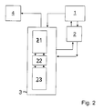
- a user is designated by the reference numeral 1.
- the user 1 can enter information about the goals, tasks and / or the field of work of the use of remote sensing data, about his person and / or about boundary conditions (ie other wishes and specifications) via an interface to a request generation device 2.
- the request generating device 2 generates requirements for the use of the remote sensing data from the information, the requests being output via an interface 2 a to a linking device 3.
- the entire arrangement can be implemented in the form of hardware and / or software.
- the linking device 3 receives the requirement profile via the interface 2a.
- the linking device can provide information the generating device 2 transmitted, z. B. if it was determined by the linking device 3 that a request can not or only partially be met. In this case, in turn, a response to the user 1 can be issued.
- the arrangement has a memory device 4, which is connected to the allocation device 3.
- the remote sensing data are stored.
- Remote sensing data products can also be stored in the memory device 4, i. H. Results of processing the remote sensing data.
- the memory device 4 may also be a spatially distributed memory device having a plurality of partial memories, which are connected to one another in particular via a data transmission network (eg the Internet).
- a data transmission network eg the Internet
- the available processing routines may also be stored, in particular a plurality of thematic processing routines, one or more of which are selected for each linking of processing routines (i.e., to fulfill a specific request profile).
- the linking device 3 has, in particular, the task of evaluating the requirements in order to be able to put together a combination of processing routines.
- object-related properties eg spectra or other properties of the data
- information relating to the acquisition of the remote sensing data eg for geometric, temporal and radiometric resolution of sensors
- the requirement profile generated by the request generation device 2 is automatically transformed by a transformation device 21 (see FIG. 2), which is connected to the interface 2 a, into a requirement profile with a plurality of technical requirements for the use of the remote sensing data.
- the technical requirements include in particular the radiometric resolution, the temporal resolution, the spectral resolution and the geographical resolution of the remote sensing data.
- transformation engine 21 generates routine requests to be satisfied by the individual selected processing routines. It transforms user requirements for the processing of the remote sensing data (eg "create a map of a certain observation area in which areas with defined vegetation are visually recognizable") into technical requirements (eg defined input variables for processing routines and output variables of processing routines). For this purpose, the transformation device 21 in particular accesses the information referred to observation objects or observation areas, the information on the processing routines and the information on their links and / or uses in the memory device 22 back. Real, ie available or future available databases are considered.
- the linking device 3 can be designed to check whether the requirements can be fulfilled on the basis of the real data stocks. This check may also extend to the existing processing routines. Is it with these Processing routines not possible to achieve the goal of processing the remote sensing data, this is detected. For example, then the user can be issued a corresponding feedback and can be changed by entering new information, the requirements profile.
- the linking device 3 also assumes an arrow pointing to the left in FIG. 1, which leads to a link 5 of selected processing routines which form a process chain in the exemplary embodiment.
- the arrow shows that the linking device 3 configures the link 5 in accordance with the requirements received via the interface 2a, ie. H. composed and linked from the existing processing routines.
- the linking device 3 has an evaluation device 23 for evaluating the requirements, which were transformed by the transformation device 21 and which were stored, for example, in the memory device 22.
- the evaluation device 23 accesses the said information on observation objects or observation areas, on the information on the processing routines and on the information on their links and / or uses in the memory device 22.
- adjustments to the interfaces of the processing routines may be required, which are also performed by the evaluation device 23.
- Such a configuration can be made not only in this embodiment, but generally by the linking device.
- the linking device 3 can also access the information stored in the memory device 4.
- the illustrated process chain consists of a total of six in the processing direction of the data from top to bottom in a row connected processing A to In this case, the processing routine A derives the data required for the processing (in particular raw data, ie data directly generated by a sensor, unchanged with respect to its information content) directly from the memory device 4.
- the last processing device F in the sequence of the process chain gives the result of the Processing at an output device 6, which is connected via an interface 6a with the user 1.
- the invention is not limited to a process chain having six processing routines. Depending on the task to be performed, more or less processing routines may be linked together.
- Processing routine D in the example is a routine for identifying particular objects (eg, defined surface areas, such as areas of particular vegetation or water areas).
- Such a processing routine processes the remote sensing data, for example, as in DE 199 39 732 A1 and / or as in the German patent application, file number 103 58 938.4 (not yet published), the entire contents of which are hereby incorporated by reference.
- this routine is or not a topic-related processing routine.
- the result is used to control thematic processing routines.
- These processing routines may be configured according to the control, that is, the processing of the remote sensing data may be changed.
- the controller may take into account information about the identified object, an identified geographic region, and / or about the geographic location of particular pixels of the remote sensing data.
- the arrangement shown in Fig. 3 has an interface IN for inputting data and outputting results of the arrangement.
- a user of the arrangement can enter information (for example, inter alia via a keyboard) and can be informed about the result (for example, via a screen and / or a printer).
- the information entered by the user is used in the arrangement, in particular when creating a task profile.
- the interface IN is connected to an allocation device MA whose task is the assignment of physical data properties to the information entered by the user.
- the allocation device MA is directly connected to a storage device DL and also each indirectly via a test device MD, a weighting device MG and an evaluation device MB connected to the memory device DL.
- the storage device DL can optionally also be connected to an archive AF.
- data properties of remote sensing data and processing routines for processing the remote sensing data are stored in the memory device DL.
- the remote sensing data itself is stored (if any) in the AF archive.
- another memory structure with, for example, only one memory device may be provided in which both the data properties, the data itself and the processing routines are stored.
- the user specifies via the interface IN, for which tasks the remote sensing data should be used.
- Such indications are e.g. the temporal spatial dynamics of a phenomenon to be detected.
- the interface IN can provide the user with a mask for entering the information that allows him to enter fuzzy information.
- the user can enter information about his person via the interface IN, from which a user profile can be created in the interface IN and / or in the assignment device MA. Further information for the user profile can also be obtained in another way, for example by accessing already stored information about the user, which is stored, for example, in the memory device DL. It may be interactive for a user (eg Dialogue with the user) an individual user profile can be created and stored. B. information on the preferred field of application of remote sensing data, knowledge from previous requests, geographical and / or temporal resolution and boundary conditions. By using the saved user profile, a pre-selection of criteria and data attributes can be made for the future.
- the user profile can also be dispensed with, for example if it is an experienced user.
- the task profile is taken as a profile created by an experienced user and this is taken into account in the selection of remote sensing data.
- the user can already make a classification of the information entered by him in predetermined criteria. For example, with the information on the tasks, he can specify a temporal and / or spatial resolution of the remote sensing data to be used.
- the user can enter preferences via the interface IN, by which he determines weights for the evaluation during the selection process.
- the weight of boundary conditions (such as costs of using the remote sensing data, data availability, period of providing remote sensing data, accuracy and / or quality of the data, minimum level of fulfillment of the user defined tasks with the selection result) may be determined.
- the task profile and the user profile can be combined with one another and the physical data properties are assigned so that a requirement profile is generated.
- the requirement profile describes the requirements to be met by the remote sensing data processing system (or remote sensing data).
- the details of the user for the task profile and for the user profile are checked for consistency, so that the arrangement with the user interactively clarify inconsistencies and / or can create a corrected task profile if desired.
- the allocation means MA preferably uses the inference method in the combination.
- fuzzy or sharp values are processed by means of predefined rules, as will be explained with reference to FIG. 9 by means of an example.
- the user gives z. For example, enter information such that words are defined as values of linguistic variables.
- the linguistic variables can then z. B. are reproduced by blurred elements in the profiles.
- the rules can be checked using examples (for example, training scenarios) and, if necessary, adjusted iteratively.
- examples for example, training scenarios
- a neural network with a plurality of neuronally-linked fuzzy logic nodes can be used, which must be trained and does not provide a clearly definite result from the outset if defined input data are used. If, on the other hand, the user enters sharply worded requirements that do not allow alternatives, the result is clear from the outset.
- At least one power profile stored in the memory device DL is then compared by the test device MD with the requirement profile of the assignment device MA.
- a plurality of performance profiles are compared with the requirement profile.
- the set of performance profiles describes the possibilities that exist to meet requirements.
- the checking device MD can return to the user, for example via the allocation device MA and the interface IN (or via another interface), that the requirement with the performance profile is wholly or partially fulfilled.
- a degree of fulfillment results from the similarity (distance) between requirement profile and performance profile. It is also conceivable that an optimized solution is returned from performance profiles (see below the description of the evaluation device MB)
- the weighting device MG performs (as already described) a pairwise comparison of properties that are stored in corresponding categories of the profiles.
- the evaluation device MB examines and evaluates the performance profile or performance profiles taking into account the requirement profile.
- the boundary conditions also preferably enter into the evaluation of the existing remote sensing data processing systems.
- the boundary conditions can be considered as components of the profiles, so z.
- one or more categories in the profiles reflect the constraints. It can be stipulated which boundary conditions can be included in the evaluation.
- a ranking of all available performance profiles (ordered according to the degree of agreement) or a ranking of the remote sensing data or remote sensing data defined by the performance profile can be created.
- Hierarchical staggering of the criteria minimizes the complexity of the request and achieves a weighting of the criteria.
- Fig. 7 shows an example of the hierarchical structure.
- the overall goal of data usage is shown in block OZ.
- the overall goal may include one or more sub-goals Z1, Z2, Z3, etc.
- criteria K1, K2, K3, etc. are defined, for each of which sub-criteria U1, U2, U3, etc. are defined. This allows the user to specify individual subcriteria, so that the overall goal can be derived from it.
- the results of the interrogation of the subcriteria can then be summarized and an overall result determined that allows to describe the overall objective. In doing so, user-defined weights of the criteria can be taken into account.
- the requirements defined by the information entered by the user can be mathematically processed.
- the MADM method Multiple Attribute Decision Making Method
- an objectification of the query is made possible in addition to the plausibility check.
- the MADM method is z. In Zimmermann, H.-J .; Gutsche, L.
- the criteria or properties defined in the requirement profile are compared with one another according to their (user-specified) weighting and with regard to the target.
- an eigenvector of the target achievement matrix is formed, and the consistency of user-specified criteria is checked using the eigenvector.
- the criteria can be corrected.
- the target can be described in the form of a vector whose elements meet the criteria, so that a distance vector can be determined by comparing the eigenvector with the target vector. For example, by forming the amount of the distance vector, the distance and thus a measure of the degree with which the goal can be achieved with the criteria are determined.
- the application of the MADM method for establishing and evaluating a target achievement matrix facilitates the decision making process and enables the objectification of the requirements by applying expert knowledge.
- the expert knowledge does not have to be available to the user, but has already flown in before.
- the method realizes a higher consistency of found data with the expectations of the users.
- the embodiment described thus constitutes an interface to the data management system which, on the basis of the MADM method, compares the respective requirement profile of the user as well as possible with the properties describing the data.
- the most suitable remote sensing data processing systems or remote sensing data for the determined requirement profile and the given boundary conditions can be output (sorted, for example, according to the evaluation result).
- the user can be informed about possible deviations between task profile and requirement profile or selected performance profile and / or informed about suitable alternatives.
- the remote sensing data best suited to the requirement profile is automatically output and / or the best-suited processing routines can be called automatically. This makes it possible to automatically generate a processing job and to process the remote sensing data.
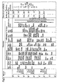
- FIG. 5 shows an example of the assignment of physical data properties (here: the geometric resolution) to the task profile data (here: work areas or work situations for which the remote sensing data is to be used).
- the geometrical resolution is assigned in the figure topic areas or work areas in the wide middle column, which is overwritten with "dimension” and which is divided into several columns.
- the geometric resolution of the remote sensing data is indicated in the figure by the right, with "pixel resolution” overwritten column.
- the numbers in this column are footnotes that are each assigned to a satellite and / or a sensor of a satellite. This sensor or satellite provides remote sensing data with geometric resolution.
- the temporal resolution of the data is of particular importance. It decides on the question of whether the acquisition of up-to-date data can be made realistically in time for the observed process. In addition, the physical potential of the sensor to fulfill the task can be questioned and / or simulated.
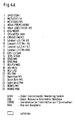
- FIG. 6 shows the relationship between geometrical resolution of sensors and the provision of data over time.
- a satellite only reaches the same relative position to a specific point on the earth's surface after a certain period of time (period duration). Therefore, only after the period again the same observation area can be observed from the same point of view. However, it is possible that part of the observation area may be re-observed earlier by the satellite, but from a different point of view and / or as part of another observation area.
- Fig. 6 the period of different satellites in days is plotted on the horizontal coordinate axis.
- the period is defined here as temporal resolution.
- the numbers entered in the diagram should be understood as footnotes indicating satellites or sensors of satellites.
- the indication of the period duration does not preclude the fact that the selection of the remote sensing data or remote sensing data processing systems also takes into account the fact that a part of an observation area and the like may be considered. U. earlier than at the end of the period can be observed again by the same sensor or satellite.
- the geometric resolution achieved by the satellites or sensors is approximately in a functional relationship to the temporal resolution.
- the functional relationship is represented by the dotted line, which decreases with increasing period to smaller values of geometric resolution. Ie. As the period increases, the geometric resolution becomes finer.
- this relationship is also used in the selection of remote sensing data.
- the consistency of the information input by the user can be checked on the basis of the relationship as described above. Thus, contradictions in this information can be uncovered, i. H. it can, for. B. an unreasonable fine required by the user geometric resolution can be discovered.
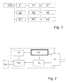
- the arrangement shown in Fig. 8 for processing remote sensing data has z.
- RS denotes a device which can execute a further selection of remote sensing data or of remote sensing data processing systems already described with reference to FIG. 3.
- the device RS may comprise the allocation device MA, the test device MD, the evaluation device MB and the weighting device MG.
- a controller CR is provided for controlling the processing of remote sensing data and for controlling the selection of the remote sensing data or systems.
- the control device CR is connected to the device RS and to a device PRO for processing the remote sensing data.
- the arrangement PRO is in turn connected to an interface or storage device RD, from which the device PRO receives remote sensing raw data for further processing.
- a selection of a remote sensing data processing system is made.
- Information about the selection is transmitted from the device RS to the control device CR.
- the selected power profile may also be transmitted from the storage device DL to the device PRO.
- the controller CR controls the operation of the device PRO such that the remote sensing data is in accordance with the selected remote sensing data processing system processed by the arrangement PRO.
- the arrangement PRO can request corresponding raw data from the interface or storage device RD.
- the arrangement PRO comprises a chain of processing routines for processing the raw data, wherein the already pre-existing processing routines are combined in accordance with the selected remote sensing data processing system.
- fuzzy characteristics of data and / or fuzzy constraints may also be taken into account.
- a so-called fuzzy evaluation method with a "fuzzy logic" can be used.
- fuzzy logic linguistic variables are used as input variables. These are understood as variables whose values are not numbers (as with deterministic variables) or statistical distributions (as with random variables), but linguistic or linguistic constructions (also called terms). These terms are assigned to blurred elements of a set of elements or represented by these elements.
- the elements can also be referred to as fuzzy value functions of a base variable.
- the base variable "price” has five fuzzy elements which mathematically describe the degree of affiliation ⁇ of a linguistic price statement (see, for example, FIG. 9: "very favorable”, “favorable”, “acceptable”, “expensive” "and” too expensive ").
- the elements are each functions that describe the degree of affiliation of the respective linguistic statement to values on a price scale.
- the elements always have the value 1 in a value range of the price scale. From this value 1, the elements steadily decrease (eg, linearly) to zero. In this case, the edge elements (in FIG. 9: “very favorable” and “too expensive”) only steadily decrease to zero on one side, while the middle elements steadily decrease to zero on both sides.
- the value range with the value 1 and the steady (that is, in particular not abrupt) decrease express the blurring of the affiliation of a price statement to a price. None of the elements overlap another element, so the range of values of both elements in the overlap area is 1. However, this may be the case in other embodiments of the method.
- the corresponding element is selected as a property of the price for the requirement profile. If a certain price in the performance profile is compared with a property comparison, the degree of affiliation for that price can be determined from the element and interpreted as a weight. If the membership degree is 1 (in the example of Fig. 9 for the price range of 0 to x1), it is full coincidence. In the area of the gradual decrease or increase in the degree of membership, the degree of membership is between 0 and 1 (in the example of FIG. 9 for the price range of x1 to x2). Therefore, for a price in this range, the match is rated with the membership grade between 0 and 1. Where the price has the membership grade 0, there is no match, i. H. the request is not fulfilled.
- the elements may be predetermined and / or properties of the elements may be entered by the user.
- the elements do not have to have constant value ranges of the degree of membership (as shown in FIG. 9).
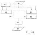
- the arrangement shown in FIG. 10 has an interface 101 for the input of data, which is connected to a first allocation device 103 and to a second allocation device 104.
- the allocators 103, 104 are connected to a memory device 102 for storing remote sensing data.
- the allocation devices 103, 104 are connected to a comparison device 105, which in turn is connected to a correction device 106.
- the comparison device 105 is connected to an optional card device 107 for creating a geographical map in the satellite projection.
- the card device 107 or the comparison device is connected to a second interface 108 for the output of data.
- FIG. 10 can also be understood as a flow chart which represents the process sequence during georeferencing.
- One or more of the above-described devices may be implemented in the form of hardware or software.
- the allocation devices 103, 104 need not be realized as separate devices, but may, for. B. software modules, which differ in particular only in that they process various geographical information as input data.
- the arrangement for automatic georeferencing can be modular according to the example described above, wherein one of the modules corresponds to one of the devices.
- the devices 103 to 105 form the core of the arrangement.
- Information about a relative movement of the satellite and the observed space body, further information and / or geographic data already derived therefrom may be available at the interface 101.
- the geographic data which can also be derived later from the information provided at the interface 101, define Observation area covered by the image matrix in usual geographic coordinates.
- the geographical data available at the interface 101 have corner coordinates and / or center or center of gravity coordinates of the observation area.
- the geographic data may come from one or more sources, e.g. B. from metadata and from subsequently corrected motion data of the satellite. This may have different sets of geographic data that are different.
- the remote sensing data in the satellite projection and the geographical information are stored in the memory device 102, and on the other hand additional information which is known a priori and can be used for the georeferencing.
- this additional information may be required in order to be able to carry out the transformation of geographical information into the satellite projection on the basis of the corner coordinates available on the interface 101.
- the additional information contains information about the size of the observation area covered by the image matrix (eg the swath width), the spatial resolution of the pixels in the nadir and the position and / or orientation of the satellite or the sensor relative to the observed space body.
- a plurality of memory devices can also be provided so that the various types of data can be stored separately from one another.
- a transformation of the geographical data (eg, map data) into the satellite projection is performed using the above-mentioned geographical data from a first source (eg, corner coordinates of metadata).
- a first source eg, corner coordinates of metadata
- mapping ie, performed similarly, for example
- geographic data from a second source e.g, corner coordinates from an actual orbital motion of the satellite.
- a reason for using a second source of information is that in an unfavorable case, the coordinates obtained from the metadata may be erroneous, e.g. B. may even be completely outside the actual observation area.
- one does not want to wait generally for the geographical data from the second source but rather to carry out a so-called "near-real-time" processing of the data.
- Algorithms for determining the observation area and for correctly assigning geographic information of a plurality of picture elements of the image matrix are implemented in the allocation devices 103, 104. There are z. For example, all pixels are assigned their geographical longitude, latitude, and other map information (eg, topographic information).
- the comparison device 105 a comparison of results of the georeferencing performed by the allocation devices 103, 104 takes place.
- only one allocation device can be provided and a comparison of a result of the performed georeferencing with a reference image can be carried out in the comparison device.
- a structural analysis can take place, which will be discussed in more detail.
- the comparison with the reference image can also be performed by the comparison device 105, wherein the results of one or both of the allocation devices 103, 104 are checked on the basis of the reference image.
- a comparison with a reference image has the advantage that it is possible to check directly on the basis of the information present in the image matrix whether the assignment of the geographical information is erroneous. Any position error can be corrected in the optionally provided correction device 106. Thus, at the output of the comparison device 105, the image matrix with correctly assigned geographical information is available.
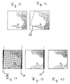
- Fig. 11 the optical data from two different overflights of a satellite over the European continent are shown.
- the land area is shown in white with a black border.
- Superimposed are observation strips 31, 32, each with two sub-strips 31 a, 31 b and 32 a, 32 b, which in turn are subdivided into individual scenes (approximately rectangular framed areas). According to this subdivision, the further processing of the satellite data takes place. The subdivision is / was made (eg by previously performed calculations) while the satellite data was entered into the map using the highly accurate coordinates. In the most favorable case, this subdivision completely covers the observation strips (such as the observation strip 31 in FIG. 11).
- the data required for the output of a geographical map in the satellite projection can then be generated, for. B. the image matrix with additional drawn geographic structures such as shorelines and / or contour lines.
- the different results of the allocation devices 103, 104, further intermediate results and / or final results of the assignment can be stored in the memory device 102 and / or in another memory device and read out again as needed.
- the method provides data in the satellite projection.
- quality control in associating the geographic information with the pels may be accomplished in the following manner:
- FIG. 12 schematically shows a scene (eg from a single image matrix in satellite projection) with a coastline 41.
- a scene eg from a single image matrix in satellite projection
- To the right (east) of the coastline 41 is a land area 42.
- To the left (west) of the coastline 41 is a water area 43.
- Part of the scene is obscured during observation by the satellite by clouds 44a, 44b, 44c, which are shown as black areas.
- Two defined sub-areas of the scene are designated by reference numerals 45, 46.
- Cloud 44c partially obscures area 46.
- cloud areas eg, clouds 44
- these areas are excluded (eg, after creating a cloud mask) for further processing during quality control (eg, structural analysis) and / or processed separately.
- quality control eg, structural analysis
- other structures eg, line-like structures, such as those created by ridges and / or the coastline 41
- line-like structures such as those created by ridges and / or the coastline 41
- edges of the regions are determined for the homogeneous regions (for example the regions 45, 46) with a constant ray spectrum. If these areas are bounded by a cloud, then in a preferred embodiment they are identified separately (in the example, area 46). The edges are used to structure the homogeneous areas. As a result, a suitable structural measure is determined, which characterizes the structure of the area based on the edges.
- edges can be described by the methods known per se for a vector graphics display (eg described in Haberburger, Peter (1995): Kir der digital Stamm für für für für für für für für für für für für as a vector graphics display (eg described in Haberburger, Peter (1995): Kir der digital Stamm für für für für für für für as a vector graphics display (eg described in Haberburger, Peter (1995): Kir der digital Stamm für für und Mustererkennung - Kunststoff, Vienna: Hanser, 1995 (ISBN 3-446-15517 -1), which is hereby incorporated by reference) be, with z. B. for each of the pixels on the edge is held as a vector element in which direction the next pixel is located on the edge.
- matches or differences can be determined. For every two vectors compared with each other, one obtains as a result of a statement whether the edges or structures are the same or not.
- a multiplicity of different vector pairs from the reference image and from the image matrix can thus be compared with one another.
- information about the geographic positions of the borders or structures is available, so that differences in position can be detected for two identically identified borders or structures.
- a statistically reliable statement can be made as to whether the geographical locations and / or orientations of the images are different.
- a correction in the assignment of the geographical information to the picture elements of the image matrix is possible.
- a corresponding structural analysis can, for. B. using a (preferably cloud-free) reference image are performed.
- the structural analysis for the reference image has already been carried out and numerical values of the structural dimensions are available for the homogenous regions present therein.
- regions for example, once again homogeneous which are suitable for evaluation are identified in the reference image and in the image matrix (for example, the checkered regions 45, 46, 50 in FIG Reference image without cloud cover represents).
- the identification of the regions in the reference image is undertaken in step S1, the identification of the regions in the image matrix in step S2.
- step S5 If no corresponding region of the image matrix is found in a correlation analysis (step S5) for a region in the reference image, it can be checked in a preferred embodiment on the basis of the cloud mask whether this region is completely covered by clouds. If so, then this reference range is deleted from further processing. In the other case, it is checked whether the assignment to a cloud-covered subarea can be established. For this purpose, a correlation analysis of the cloud-free edge part of the region (for example of the region with corresponding edge parts of the relevant entire reference region is undertaken.
- step S6 If the mutually corresponding regions in the reference image and in the image matrix are assigned to one another (step S6), it can be determined, for example, by the following procedure, whether a mispositioning or misorientation of the image matrix exists:
- the geographical positions of the regions are determined for the images (in step S7 for the reference image and in step S8 for the image matrix), in particular the geographical positions of the region centers, the geographical positions of uniquely identifiable points z.
- the geographical positions of the region centers are determined for the images (in step S7 for the reference image and in step S8 for the image matrix), in particular the geographical positions of the region centers, the geographical positions of uniquely identifiable points z.
- the region centroids eg, centroids 47, 48, 51 in Fig. 13.
- Focal points are to be understood as the points whose integral of the distances multiplied by themselves are minimal to the edges of the range.
- the relative positions are shown in FIG. 13 by connecting lines of the centroids 47, 48, 51. From the plurality of relative positions and from a comparison of the situation (step S9) in the two images can be overall, the position error and the orientation error again determine (step S10). In this case, in turn, an average over the position differences and / or orientation differences of different groups with z. B. in each case at least three areas are formed.
- FIGS. Fig. 15 shows initial cartographic data obtained, for example, by a projection perpendicular to the surface of a planet. Dark areas are represented. Bright are shown water surfaces.
- Fig. 16 shows the same map detail as Fig. 15, but also showing a partial area 25 corresponding to the area observed by a satellite (i.e., an image matrix). In other words, information is available only for the sub-area 25 in the image matrix.
- a satellite i.e., an image matrix
- the corner coordinates of the observed sub-area 25 are determined (eg from the metadata). Subsequently, this sub-area 25 is rotated, so that it corresponds to an orientation of the recorded image and thus the cartographic information is only parallel (eg, transversely to the line direction of the image matrix) shifted to the image data.
- FIG. 17 wherein the sub-area covered by the image matrix is between lines 26 and 27.
- the observed subarea in the map projection is not quite rectangular, but is distorted in the manner of a parallelogram.
- the sub-areas lying outside the lines 26, 27 are wedge-shaped and, in the embodiment, correspond to the rotation of the planet while the satellite flies over the planet.
- the rotation of the planet is eliminated.
- the result is shown in FIG. Three of the edges of the map section now coincide with the observed area.
- a line 28 is drawn, which separates the matching with the observed area portion of the map section of another sub-area for which there are no observation data.
- the subarea for which there is no observation data is truncated. Subsequently, e.g. the land / water boundaries recognizable from the map section are taken over into the image matrix or into a corresponding matrix for evaluating distances in the image matrix, or geographic information about the land / water boundary course is assigned to the image elements of the image matrix.
Landscapes
- Engineering & Computer Science (AREA)
- General Physics & Mathematics (AREA)
- Physics & Mathematics (AREA)
- Theoretical Computer Science (AREA)
- Remote Sensing (AREA)
- Multimedia (AREA)
- Astronomy & Astrophysics (AREA)
- Radar, Positioning & Navigation (AREA)
- Computer Vision & Pattern Recognition (AREA)
- Image Processing (AREA)
- Selective Calling Equipment (AREA)
- Radio Relay Systems (AREA)
- Photoreceptors In Electrophotography (AREA)
- Detection And Prevention Of Errors In Transmission (AREA)
Applications Claiming Priority (3)
| Application Number | Priority Date | Filing Date | Title |
|---|---|---|---|
| DE200410045556 DE102004045556A1 (de) | 2004-09-15 | 2004-09-15 | Verarbeitung von Fernerkundungsdaten |
| DE200410045562 DE102004045562A1 (de) | 2004-09-15 | 2004-09-15 | Auswahl von Fernerkundungsdaten |
| DE200410045563 DE102004045563A1 (de) | 2004-09-15 | 2004-09-15 | Automatische Georeferenzierung von Fernerkundungsdaten |
Publications (3)
| Publication Number | Publication Date |
|---|---|
| EP1637838A2 true EP1637838A2 (fr) | 2006-03-22 |
| EP1637838A3 EP1637838A3 (fr) | 2006-06-21 |
| EP1637838B1 EP1637838B1 (fr) | 2009-09-23 |
Family
ID=35457517
Family Applications (1)
| Application Number | Title | Priority Date | Filing Date |
|---|---|---|---|
| EP05090253A Expired - Lifetime EP1637838B1 (fr) | 2004-09-15 | 2005-09-01 | Traitement de données de télédétection |
Country Status (4)
| Country | Link |
|---|---|
| US (1) | US7246040B2 (fr) |
| EP (1) | EP1637838B1 (fr) |
| AT (1) | ATE443846T1 (fr) |
| DE (1) | DE502005008173D1 (fr) |
Cited By (5)
| Publication number | Priority date | Publication date | Assignee | Title |
|---|---|---|---|---|
| CN111080581A (zh) * | 2019-12-02 | 2020-04-28 | 王睿 | 一种遥感图像快速处理方法 |
| CN114491108A (zh) * | 2021-12-30 | 2022-05-13 | 中科星通(廊坊)信息技术有限公司 | 一种基于多源遥感应用数据的在线分类系统及方法 |
| CN115033728A (zh) * | 2022-05-10 | 2022-09-09 | 湖南省第二测绘院 | 全球卫星影像搜索引擎数据爬取与归一化方法及系统 |
| CN115307738A (zh) * | 2022-08-23 | 2022-11-08 | 中国科学院地理科学与资源研究所 | 一种基于三元空间的地表温度分解方法 |
| CN118172575A (zh) * | 2024-05-15 | 2024-06-11 | 济南市勘察测绘研究院 | 一种测绘数据智能管理系统 |
Families Citing this family (45)
| Publication number | Priority date | Publication date | Assignee | Title |
|---|---|---|---|---|
| US8135713B2 (en) * | 2006-03-31 | 2012-03-13 | Sap Ag | Sourcing controller |
| US7991226B2 (en) * | 2007-10-12 | 2011-08-02 | Pictometry International Corporation | System and process for color-balancing a series of oblique images |
| US20110047086A1 (en) * | 2007-11-14 | 2011-02-24 | Bank Of America Corporation | Evaluating Environmental Sustainability |
| US20090125347A1 (en) * | 2007-11-14 | 2009-05-14 | Bank Of America Corporation | Determining Lease Quality |
| CN102607529A (zh) * | 2012-03-30 | 2012-07-25 | 中国神华能源股份有限公司 | 矿区环境的测量方法、装置以及数据处理设备 |
| CN102706328A (zh) * | 2012-04-28 | 2012-10-03 | 中国神华能源股份有限公司 | 地面沉陷区域的检测方法和装置及数据处理设备 |
| US9805863B2 (en) | 2012-07-27 | 2017-10-31 | Thoratec Corporation | Magnetic power transmission utilizing phased transmitter coil arrays and phased receiver coil arrays |
| WO2014018971A1 (fr) | 2012-07-27 | 2014-01-30 | Thoratec Corporation | Systèmes de transfert de puissance résonants avec algorithme de protection |
| WO2014018973A1 (fr) | 2012-07-27 | 2014-01-30 | Thoratec Corporation | Bobines et systèmes de transmission de puissance résonants |
| WO2014018972A1 (fr) | 2012-07-27 | 2014-01-30 | Thoratec Corporation | Modélisation informatique pour systèmes de transfert de puissance résonants |
| EP2878061B1 (fr) | 2012-07-27 | 2023-10-25 | Tc1 Llc | Gestion thermique pour des systèmes de transfert de puissance sans fil implantables |
| US10383990B2 (en) | 2012-07-27 | 2019-08-20 | Tc1 Llc | Variable capacitor for resonant power transfer systems |
| WO2014018969A2 (fr) | 2012-07-27 | 2014-01-30 | Thoratec Corporation | Système de transfert de puissance résonant et procédé d'estimation d'état de système |
| US9287040B2 (en) | 2012-07-27 | 2016-03-15 | Thoratec Corporation | Self-tuning resonant power transfer systems |
| WO2014145664A1 (fr) | 2013-03-15 | 2014-09-18 | Thoratec Corporation | Boîtier de test implantable intégré comprenant des ailettes et des boucles de bobine |
| US10373756B2 (en) | 2013-03-15 | 2019-08-06 | Tc1 Llc | Malleable TETs coil with improved anatomical fit |
| US10695476B2 (en) | 2013-11-11 | 2020-06-30 | Tc1 Llc | Resonant power transfer systems with communications |
| WO2015070205A1 (fr) | 2013-11-11 | 2015-05-14 | Thoratec Corporation | Systèmes à communications de transfert de puissance par résonance |
| US9855437B2 (en) | 2013-11-11 | 2018-01-02 | Tc1 Llc | Hinged resonant power transfer coil |
| WO2015134871A1 (fr) | 2014-03-06 | 2015-09-11 | Thoratec Corporation | Connecteurs électriques pour dispositifs implantables |
| CN103900534A (zh) * | 2014-03-09 | 2014-07-02 | 浙江海洋学院 | 基于3s技术的海岛资源动态监测系统 |
| CN103900533A (zh) * | 2014-03-09 | 2014-07-02 | 浙江海洋学院 | 基于3s技术的海岛资源动态监测方法 |
| CN103900537A (zh) * | 2014-04-08 | 2014-07-02 | 浙江海洋学院 | 一种基于3s技术的海岛资源动态监测系统及方法 |
| WO2016049039A1 (fr) | 2014-09-22 | 2016-03-31 | Thoratec Corporation | Conceptions d'antenne pour communication entre un implant alimenté sans fil et un dispositif externe à l'extérieur du corps |
| WO2016057525A1 (fr) | 2014-10-06 | 2016-04-14 | Thoratec Corporation | Connecteur multiaxial pour dispositifs implantables |
| US10148126B2 (en) | 2015-08-31 | 2018-12-04 | Tc1 Llc | Wireless energy transfer system and wearables |
| CN105117294B (zh) * | 2015-09-15 | 2018-03-23 | 民政部国家减灾中心 | 多机多任务并行卫星遥感影像正射校正处理系统及其方法 |
| CN105157673A (zh) * | 2015-09-21 | 2015-12-16 | 山东大学 | 隧道拱顶沉降自动测量报警仪器及使用方法 |
| WO2017062552A1 (fr) | 2015-10-07 | 2017-04-13 | Tc1 Llc | Systèmes de transfert d'énergie par résonance à optimisation du rendement basée sur l'impédance du récepteur |
| EP3497775B1 (fr) | 2016-09-21 | 2022-07-13 | Tc1 Llc | Systèmes et procédés de localisation de dispositifs de transmission de puissance sans fil implantés |
| WO2018136592A2 (fr) | 2017-01-18 | 2018-07-26 | Tc1 Llc | Systèmes et procédés de transfert d'énergie transcutané à l'aide de micro-aiguilles |
| GB2559566B (en) * | 2017-02-08 | 2022-01-12 | Ordnance Survey Ltd | Topographic data machine learning method and system |
| CN106705933A (zh) * | 2017-02-23 | 2017-05-24 | 云南云岭高速公路工程咨询有限公司 | 一种脚手架沉降观察及沉降量测量的安全预警系统 |
| RU2699821C2 (ru) * | 2017-12-11 | 2019-09-11 | Акционерное общество "Информационные спутниковые системы" имени академика М.Ф. Решетнёва" | Способ установления оптимального значения эквивалентной изотропно излучаемой мощности передающей системы космического аппарата на низкой круговой орбите для связи со спутником-ретранслятором на высокой круговой орбите, оснащенным приемной антенной с узким управляемым лучом |
| US10770923B2 (en) | 2018-01-04 | 2020-09-08 | Tc1 Llc | Systems and methods for elastic wireless power transmission devices |
| CN109344188B (zh) * | 2018-09-11 | 2022-10-04 | 北京航空航天大学 | 遥感卫星效能人工智能统计方法 |
| WO2020167679A1 (fr) * | 2019-02-11 | 2020-08-20 | Viasat Inc. | Codage delta pour détection à distance |
| CN110263116B (zh) * | 2019-06-21 | 2022-02-18 | 苏州超擎图形软件科技发展有限公司 | 一种支持动态投影转换的瓦片地图发布方法及装置 |
| CN112579677B (zh) * | 2020-11-27 | 2023-07-18 | 福建省星云大数据应用服务有限公司 | 一种卫星遥感影像自动处理方法 |
| CN112945384B (zh) * | 2021-03-01 | 2022-06-28 | 中国科学院空天信息创新研究院 | 一种多角度偏振卫星的数据预处理方法 |
| CN114462199B (zh) * | 2021-12-29 | 2023-04-18 | 中科星通(廊坊)信息技术有限公司 | 遥感数字试验场选址与评价方法 |
| JP7706416B2 (ja) * | 2022-05-16 | 2025-07-11 | 三菱電機株式会社 | 利用装置、利用方法および利用プログラム |
| CN115292433B (zh) * | 2022-08-12 | 2024-05-24 | 南京三万物联网科技有限公司 | 基于摄像元数据转换gis统一数据的几何代数编码方法 |
| CN115878826B (zh) * | 2022-12-02 | 2026-01-27 | 湖北大学 | 多源遥感影像元数据溯源信息组织方法与管理系统 |
| CN116049482B (zh) * | 2023-03-31 | 2023-10-20 | 北京数慧时空信息技术有限公司 | 基于时空域的遥感影像统筹方法 |
Citations (5)
| Publication number | Priority date | Publication date | Assignee | Title |
|---|---|---|---|---|
| DE19939732A1 (de) | 1999-08-16 | 2001-03-01 | Deutsch Zentr Luft & Raumfahrt | Verfahren zur automatischen Detektion und Identifikation von Objekten in multispektralen Fernerkundungsdaten |
| EP1091188A1 (fr) | 1999-07-16 | 2001-04-11 | Deutsches Zentrum für Luft- und Raumfahrt e.V. | Méthode de correction des influences de l'atmosphère sur les données multispectrales de télédétection optique |
| DE10354752A1 (de) | 2002-11-25 | 2004-08-19 | Deutsches Zentrum für Luft- und Raumfahrt e.V. | Verfahren und Vorrichtung zur automatischen Entzerrung von einkanaligen oder mehrkanaligen Bildern |
| DE10358938A1 (de) | 2003-12-15 | 2005-07-21 | Deutsches Zentrum für Luft- und Raumfahrt e.V. | Verfahren und Vorrichtung zur mindestens teilweise automatisierten Auswertung von Fernerkundungsdaten |
| DE102004024595B3 (de) | 2004-04-30 | 2005-08-18 | Deutsches Zentrum für Luft- und Raumfahrt e.V. | Verfahren und Vorrichtung zum Feststellen einer Nutzbarkeit von Fernerkundungsdaten |
Family Cites Families (1)
| Publication number | Priority date | Publication date | Assignee | Title |
|---|---|---|---|---|
| US20030018510A1 (en) * | 2001-03-30 | 2003-01-23 | E-Know | Method, system, and software for enterprise action management |
-
2005
- 2005-09-01 AT AT05090253T patent/ATE443846T1/de not_active IP Right Cessation
- 2005-09-01 EP EP05090253A patent/EP1637838B1/fr not_active Expired - Lifetime
- 2005-09-01 DE DE502005008173T patent/DE502005008173D1/de not_active Expired - Lifetime
- 2005-09-15 US US11/227,894 patent/US7246040B2/en not_active Expired - Fee Related
Patent Citations (5)
| Publication number | Priority date | Publication date | Assignee | Title |
|---|---|---|---|---|
| EP1091188A1 (fr) | 1999-07-16 | 2001-04-11 | Deutsches Zentrum für Luft- und Raumfahrt e.V. | Méthode de correction des influences de l'atmosphère sur les données multispectrales de télédétection optique |
| DE19939732A1 (de) | 1999-08-16 | 2001-03-01 | Deutsch Zentr Luft & Raumfahrt | Verfahren zur automatischen Detektion und Identifikation von Objekten in multispektralen Fernerkundungsdaten |
| DE10354752A1 (de) | 2002-11-25 | 2004-08-19 | Deutsches Zentrum für Luft- und Raumfahrt e.V. | Verfahren und Vorrichtung zur automatischen Entzerrung von einkanaligen oder mehrkanaligen Bildern |
| DE10358938A1 (de) | 2003-12-15 | 2005-07-21 | Deutsches Zentrum für Luft- und Raumfahrt e.V. | Verfahren und Vorrichtung zur mindestens teilweise automatisierten Auswertung von Fernerkundungsdaten |
| DE102004024595B3 (de) | 2004-04-30 | 2005-08-18 | Deutsches Zentrum für Luft- und Raumfahrt e.V. | Verfahren und Vorrichtung zum Feststellen einer Nutzbarkeit von Fernerkundungsdaten |
Non-Patent Citations (3)
| Title |
|---|
| PETER, PRAXIS DER DIGITALEN BILDVERARBEITUNG UND MUSTERERKENNUNG .- MÜNCHEN, 1995 |
| WIEN, HANSER, 1995 |
| ZIMMERMANN, H.-J.; GUTSCHE, L.: "MULTI-CRITERIA ANALYSE - EINFÜHRUNG IN DIE THEORIE DER ENTSCHEIDUNGEN BEI MEHRFACHZIELSETZUNGEN", 1991, SPRINGER-VERLAG |
Cited By (6)
| Publication number | Priority date | Publication date | Assignee | Title |
|---|---|---|---|---|
| CN111080581A (zh) * | 2019-12-02 | 2020-04-28 | 王睿 | 一种遥感图像快速处理方法 |
| CN111080581B (zh) * | 2019-12-02 | 2023-04-28 | 王睿 | 一种遥感图像快速处理方法 |
| CN114491108A (zh) * | 2021-12-30 | 2022-05-13 | 中科星通(廊坊)信息技术有限公司 | 一种基于多源遥感应用数据的在线分类系统及方法 |
| CN115033728A (zh) * | 2022-05-10 | 2022-09-09 | 湖南省第二测绘院 | 全球卫星影像搜索引擎数据爬取与归一化方法及系统 |
| CN115307738A (zh) * | 2022-08-23 | 2022-11-08 | 中国科学院地理科学与资源研究所 | 一种基于三元空间的地表温度分解方法 |
| CN118172575A (zh) * | 2024-05-15 | 2024-06-11 | 济南市勘察测绘研究院 | 一种测绘数据智能管理系统 |
Also Published As
| Publication number | Publication date |
|---|---|
| DE502005008173D1 (de) | 2009-11-05 |
| US20060080037A1 (en) | 2006-04-13 |
| ATE443846T1 (de) | 2009-10-15 |
| US7246040B2 (en) | 2007-07-17 |
| EP1637838A3 (fr) | 2006-06-21 |
| EP1637838B1 (fr) | 2009-09-23 |
Similar Documents
| Publication | Publication Date | Title |
|---|---|---|
| EP1637838B1 (fr) | Traitement de données de télédétection | |
| DE112021000243B4 (de) | Verfahren, system und computerprogrammprodukt zur bestimmung von kulturpflanzentyp und/oder aussaattermin | |
| DE10354752B4 (de) | Verfahren und Vorrichtung zur automatischen Entzerrung von einkanaligen oder mehrkanaligen Bildern | |
| Fisette et al. | Annual space-based crop inventory for Canada: 2009–2014 | |
| EP3017319A1 (fr) | Procédé permettant de déterminer la trajectoire d'objets physiques mobiles dans un espace, sur la base des données de détection de plusieurs capteurs | |
| DE202012013403U1 (de) | Erfassen und Verarbeiten adaptiver Bilder mit Bildanalyse-Rückmeldung | |
| McCloy | Resource management information systems: Remote sensing, GIS and modelling | |
| DE102012221667A1 (de) | Vorrichtung und Verfahren zum Verarbeiten von Fernerkundungsdaten | |
| DE102005010155A1 (de) | Verfahren und Anordnung zum Gewinnen von Fernerkundungsdaten | |
| EP4100695B1 (fr) | Procédé de géoréférencement de données de télédétection | |
| EP0634628B1 (fr) | Procédé pour l'observation de la terre | |
| DE102014205083B3 (de) | Erstellen von Karten mit Küstenlinien | |
| WO1994028500A1 (fr) | Procede et systeme de filtrage spatial | |
| EP4073745A1 (fr) | Procédé et dispositif de détermination de parallaxe d'images capturées par un système de caméra à multiples objectifs | |
| DE102021205730B3 (de) | Verfahren und vorrichtung zum verorten einer von der ferne aus aufgenommenen bildaufnahme eines objektes | |
| Tatem et al. | Super‐resolution Land Cover Mapping from Remotely Sensed Imagery using a Hopfield Neural Network | |
| DE102004045563A1 (de) | Automatische Georeferenzierung von Fernerkundungsdaten | |
| WO2023079063A1 (fr) | Procédé et système de collecte de données sur un champ utilisé pour l'agriculture | |
| EP1486920A2 (fr) | Procédé de télédétection | |
| Meyer | Segmentation and symbolic description for a classification of agricultural areas with multispectral scanner data | |
| DE102004045562A1 (de) | Auswahl von Fernerkundungsdaten | |
| DE102024204223B3 (de) | Verfahren und eine Anordnung zum Verbessern einer geometrischen Auflösung von Fernerkundungsdaten | |
| DE102004024595B3 (de) | Verfahren und Vorrichtung zum Feststellen einer Nutzbarkeit von Fernerkundungsdaten | |
| Dekker | Object-based updating of land-use maps of urban areas using satellite remote sensing | |
| EP2732306B1 (fr) | Procédé pour compléter et corriger les images radar météorologiques numériques |
Legal Events
| Date | Code | Title | Description |
|---|---|---|---|
| PUAI | Public reference made under article 153(3) epc to a published international application that has entered the european phase |
Free format text: ORIGINAL CODE: 0009012 |
|
| AK | Designated contracting states |
Kind code of ref document: A2 Designated state(s): AT BE BG CH CY CZ DE DK EE ES FI FR GB GR HU IE IS IT LI LT LU LV MC NL PL PT RO SE SI SK TR |
|
| AX | Request for extension of the european patent |
Extension state: AL BA HR MK YU |
|
| RIC1 | Information provided on ipc code assigned before grant |
Ipc: G01C 11/04 20060101AFI20060227BHEP Ipc: G06T 7/00 20060101ALI20051221BHEP |
|
| PUAL | Search report despatched |
Free format text: ORIGINAL CODE: 0009013 |
|
| RAP1 | Party data changed (applicant data changed or rights of an application transferred) |
Owner name: DEUTSCHES ZENTRUM FUER LUFT- UND RAUMFAHRT E.V. |
|
| AK | Designated contracting states |
Kind code of ref document: A3 Designated state(s): AT BE BG CH CY CZ DE DK EE ES FI FR GB GR HU IE IS IT LI LT LU LV MC NL PL PT RO SE SI SK TR |
|
| AX | Request for extension of the european patent |
Extension state: AL BA HR MK YU |
|
| 17P | Request for examination filed |
Effective date: 20061213 |
|
| 17Q | First examination report despatched |
Effective date: 20070117 |
|
| AKX | Designation fees paid |
Designated state(s): AT BE BG CH CY CZ DE DK EE ES FI FR GB GR HU IE IS IT LI LT LU LV MC NL PL PT RO SE SI SK TR |
|
| GRAP | Despatch of communication of intention to grant a patent |
Free format text: ORIGINAL CODE: EPIDOSNIGR1 |
|
| GRAS | Grant fee paid |
Free format text: ORIGINAL CODE: EPIDOSNIGR3 |
|
| GRAA | (expected) grant |
Free format text: ORIGINAL CODE: 0009210 |
|
| AK | Designated contracting states |
Kind code of ref document: B1 Designated state(s): AT BE BG CH CY CZ DE DK EE ES FI FR GB GR HU IE IS IT LI LT LU LV MC NL PL PT RO SE SI SK TR |
|
| REG | Reference to a national code |
Ref country code: GB Ref legal event code: FG4D Free format text: NOT ENGLISH |
|
| REG | Reference to a national code |
Ref country code: CH Ref legal event code: EP |
|
| REG | Reference to a national code |
Ref country code: IE Ref legal event code: FG4D |
|
| REF | Corresponds to: |
Ref document number: 502005008173 Country of ref document: DE Date of ref document: 20091105 Kind code of ref document: P |
|
| PG25 | Lapsed in a contracting state [announced via postgrant information from national office to epo] |
Ref country code: FI Free format text: LAPSE BECAUSE OF FAILURE TO SUBMIT A TRANSLATION OF THE DESCRIPTION OR TO PAY THE FEE WITHIN THE PRESCRIBED TIME-LIMIT Effective date: 20090923 Ref country code: SE Free format text: LAPSE BECAUSE OF FAILURE TO SUBMIT A TRANSLATION OF THE DESCRIPTION OR TO PAY THE FEE WITHIN THE PRESCRIBED TIME-LIMIT Effective date: 20090923 Ref country code: LT Free format text: LAPSE BECAUSE OF FAILURE TO SUBMIT A TRANSLATION OF THE DESCRIPTION OR TO PAY THE FEE WITHIN THE PRESCRIBED TIME-LIMIT Effective date: 20090923 |
|
| LTIE | Lt: invalidation of european patent or patent extension |
Effective date: 20090923 |
|
| PG25 | Lapsed in a contracting state [announced via postgrant information from national office to epo] |
Ref country code: PL Free format text: LAPSE BECAUSE OF FAILURE TO SUBMIT A TRANSLATION OF THE DESCRIPTION OR TO PAY THE FEE WITHIN THE PRESCRIBED TIME-LIMIT Effective date: 20090923 Ref country code: LV Free format text: LAPSE BECAUSE OF FAILURE TO SUBMIT A TRANSLATION OF THE DESCRIPTION OR TO PAY THE FEE WITHIN THE PRESCRIBED TIME-LIMIT Effective date: 20090923 Ref country code: SI Free format text: LAPSE BECAUSE OF FAILURE TO SUBMIT A TRANSLATION OF THE DESCRIPTION OR TO PAY THE FEE WITHIN THE PRESCRIBED TIME-LIMIT Effective date: 20090923 |
|
| NLV1 | Nl: lapsed or annulled due to failure to fulfill the requirements of art. 29p and 29m of the patents act | ||
| PG25 | Lapsed in a contracting state [announced via postgrant information from national office to epo] |
Ref country code: CY Free format text: LAPSE BECAUSE OF FAILURE TO SUBMIT A TRANSLATION OF THE DESCRIPTION OR TO PAY THE FEE WITHIN THE PRESCRIBED TIME-LIMIT Effective date: 20090923 |
|
| REG | Reference to a national code |
Ref country code: IE Ref legal event code: FD4D |
|
| PG25 | Lapsed in a contracting state [announced via postgrant information from national office to epo] |
Ref country code: IS Free format text: LAPSE BECAUSE OF FAILURE TO SUBMIT A TRANSLATION OF THE DESCRIPTION OR TO PAY THE FEE WITHIN THE PRESCRIBED TIME-LIMIT Effective date: 20100123 Ref country code: IE Free format text: LAPSE BECAUSE OF FAILURE TO SUBMIT A TRANSLATION OF THE DESCRIPTION OR TO PAY THE FEE WITHIN THE PRESCRIBED TIME-LIMIT Effective date: 20090923 Ref country code: CZ Free format text: LAPSE BECAUSE OF FAILURE TO SUBMIT A TRANSLATION OF THE DESCRIPTION OR TO PAY THE FEE WITHIN THE PRESCRIBED TIME-LIMIT Effective date: 20090923 Ref country code: EE Free format text: LAPSE BECAUSE OF FAILURE TO SUBMIT A TRANSLATION OF THE DESCRIPTION OR TO PAY THE FEE WITHIN THE PRESCRIBED TIME-LIMIT Effective date: 20090923 Ref country code: RO Free format text: LAPSE BECAUSE OF FAILURE TO SUBMIT A TRANSLATION OF THE DESCRIPTION OR TO PAY THE FEE WITHIN THE PRESCRIBED TIME-LIMIT Effective date: 20090923 Ref country code: ES Free format text: LAPSE BECAUSE OF FAILURE TO SUBMIT A TRANSLATION OF THE DESCRIPTION OR TO PAY THE FEE WITHIN THE PRESCRIBED TIME-LIMIT Effective date: 20100103 Ref country code: PT Free format text: LAPSE BECAUSE OF FAILURE TO SUBMIT A TRANSLATION OF THE DESCRIPTION OR TO PAY THE FEE WITHIN THE PRESCRIBED TIME-LIMIT Effective date: 20100125 |
|
| PG25 | Lapsed in a contracting state [announced via postgrant information from national office to epo] |
Ref country code: SK Free format text: LAPSE BECAUSE OF FAILURE TO SUBMIT A TRANSLATION OF THE DESCRIPTION OR TO PAY THE FEE WITHIN THE PRESCRIBED TIME-LIMIT Effective date: 20090923 |
|
| PG25 | Lapsed in a contracting state [announced via postgrant information from national office to epo] |
Ref country code: DK Free format text: LAPSE BECAUSE OF FAILURE TO SUBMIT A TRANSLATION OF THE DESCRIPTION OR TO PAY THE FEE WITHIN THE PRESCRIBED TIME-LIMIT Effective date: 20090923 Ref country code: NL Free format text: LAPSE BECAUSE OF FAILURE TO SUBMIT A TRANSLATION OF THE DESCRIPTION OR TO PAY THE FEE WITHIN THE PRESCRIBED TIME-LIMIT Effective date: 20090923 |
|
| PLBE | No opposition filed within time limit |
Free format text: ORIGINAL CODE: 0009261 |
|
| STAA | Information on the status of an ep patent application or granted ep patent |
Free format text: STATUS: NO OPPOSITION FILED WITHIN TIME LIMIT |
|
| 26N | No opposition filed |
Effective date: 20100624 |
|
| PG25 | Lapsed in a contracting state [announced via postgrant information from national office to epo] |
Ref country code: GR Free format text: LAPSE BECAUSE OF FAILURE TO SUBMIT A TRANSLATION OF THE DESCRIPTION OR TO PAY THE FEE WITHIN THE PRESCRIBED TIME-LIMIT Effective date: 20091224 |
|
| BERE | Be: lapsed |
Owner name: DEUTSCHES ZENTRUM FUR LUFT- UND RAUMFAHRT E.V. Effective date: 20100930 |
|
| PG25 | Lapsed in a contracting state [announced via postgrant information from national office to epo] |
Ref country code: MC Free format text: LAPSE BECAUSE OF NON-PAYMENT OF DUE FEES Effective date: 20100930 |
|
| REG | Reference to a national code |
Ref country code: CH Ref legal event code: PL |
|
| GBPC | Gb: european patent ceased through non-payment of renewal fee |
Effective date: 20100901 |
|
| REG | Reference to a national code |
Ref country code: FR Ref legal event code: ST Effective date: 20110531 |
|
| PG25 | Lapsed in a contracting state [announced via postgrant information from national office to epo] |
Ref country code: LI Free format text: LAPSE BECAUSE OF NON-PAYMENT OF DUE FEES Effective date: 20100930 Ref country code: FR Free format text: LAPSE BECAUSE OF NON-PAYMENT OF DUE FEES Effective date: 20100930 Ref country code: BE Free format text: LAPSE BECAUSE OF NON-PAYMENT OF DUE FEES Effective date: 20100930 Ref country code: CH Free format text: LAPSE BECAUSE OF NON-PAYMENT OF DUE FEES Effective date: 20100930 |
|
| PG25 | Lapsed in a contracting state [announced via postgrant information from national office to epo] |
Ref country code: GB Free format text: LAPSE BECAUSE OF NON-PAYMENT OF DUE FEES Effective date: 20100901 |
|
| PG25 | Lapsed in a contracting state [announced via postgrant information from national office to epo] |
Ref country code: AT Free format text: LAPSE BECAUSE OF NON-PAYMENT OF DUE FEES Effective date: 20100901 |
|
| PG25 | Lapsed in a contracting state [announced via postgrant information from national office to epo] |
Ref country code: HU Free format text: LAPSE BECAUSE OF FAILURE TO SUBMIT A TRANSLATION OF THE DESCRIPTION OR TO PAY THE FEE WITHIN THE PRESCRIBED TIME-LIMIT Effective date: 20100324 Ref country code: BG Free format text: LAPSE BECAUSE OF FAILURE TO SUBMIT A TRANSLATION OF THE DESCRIPTION OR TO PAY THE FEE WITHIN THE PRESCRIBED TIME-LIMIT Effective date: 20090923 Ref country code: LU Free format text: LAPSE BECAUSE OF NON-PAYMENT OF DUE FEES Effective date: 20100901 |
|
| PG25 | Lapsed in a contracting state [announced via postgrant information from national office to epo] |
Ref country code: TR Free format text: LAPSE BECAUSE OF FAILURE TO SUBMIT A TRANSLATION OF THE DESCRIPTION OR TO PAY THE FEE WITHIN THE PRESCRIBED TIME-LIMIT Effective date: 20090923 |
|
| PG25 | Lapsed in a contracting state [announced via postgrant information from national office to epo] |
Ref country code: IT Free format text: LAPSE BECAUSE OF NON-PAYMENT OF DUE FEES Effective date: 20100901 |
|
| PGFP | Annual fee paid to national office [announced via postgrant information from national office to epo] |
Ref country code: DE Payment date: 20240808 Year of fee payment: 20 |
|
| REG | Reference to a national code |
Ref country code: DE Ref legal event code: R071 Ref document number: 502005008173 Country of ref document: DE |