EP3497775B1 - Systèmes et procédés de localisation de dispositifs de transmission de puissance sans fil implantés - Google Patents
Systèmes et procédés de localisation de dispositifs de transmission de puissance sans fil implantés Download PDFInfo
- Publication number
- EP3497775B1 EP3497775B1 EP17784720.9A EP17784720A EP3497775B1 EP 3497775 B1 EP3497775 B1 EP 3497775B1 EP 17784720 A EP17784720 A EP 17784720A EP 3497775 B1 EP3497775 B1 EP 3497775B1
- Authority
- EP
- European Patent Office
- Prior art keywords
- magnetic
- coil
- sensor array
- coupling
- magnetic sensor
- Prior art date
- Legal status (The legal status is an assumption and is not a legal conclusion. Google has not performed a legal analysis and makes no representation as to the accuracy of the status listed.)
- Active
Links
Images




Classifications
-
- H—ELECTRICITY
- H02—GENERATION; CONVERSION OR DISTRIBUTION OF ELECTRIC POWER
- H02J—ELECTRIC POWER NETWORKS; CIRCUIT ARRANGEMENTS OR SYSTEMS FOR SUPPLYING OR DISTRIBUTING ELECTRIC POWER; SYSTEMS FOR STORING ELECTRIC ENERGY
- H02J50/00—Circuit arrangements or systems for wireless supply or distribution of electric power
- H02J50/90—Circuit arrangements or systems for wireless supply or distribution of electric power involving detection or optimisation of position, e.g. alignment
-
- A—HUMAN NECESSITIES
- A61—MEDICAL OR VETERINARY SCIENCE; HYGIENE
- A61B—DIAGNOSIS; SURGERY; IDENTIFICATION
- A61B5/00—Measuring for diagnostic purposes; Identification of persons
- A61B5/06—Devices, other than using radiation, for detecting or locating foreign bodies ; Determining position of diagnostic devices within or on the body of the patient
- A61B5/061—Determining position of a probe within the body employing means separate from the probe, e.g. sensing internal probe position employing impedance electrodes on the surface of the body
- A61B5/062—Determining position of a probe within the body employing means separate from the probe, e.g. sensing internal probe position employing impedance electrodes on the surface of the body using magnetic field
-
- A—HUMAN NECESSITIES
- A61—MEDICAL OR VETERINARY SCIENCE; HYGIENE
- A61B—DIAGNOSIS; SURGERY; IDENTIFICATION
- A61B90/00—Instruments, implements or accessories specially adapted for surgery or diagnosis and not covered by any of the groups A61B1/00 - A61B50/00, e.g. for luxation treatment or for protecting wound edges
- A61B90/39—Markers, e.g. radio-opaque or breast lesions markers
-
- A—HUMAN NECESSITIES
- A61—MEDICAL OR VETERINARY SCIENCE; HYGIENE
- A61N—ELECTROTHERAPY; MAGNETOTHERAPY; RADIATION THERAPY; ULTRASOUND THERAPY
- A61N1/00—Electrotherapy; Circuits therefor
- A61N1/18—Applying electric currents by contact electrodes
- A61N1/32—Applying electric currents by contact electrodes alternating or intermittent currents
- A61N1/36—Applying electric currents by contact electrodes alternating or intermittent currents for stimulation
- A61N1/372—Arrangements in connection with the implantation of stimulators
- A61N1/37211—Means for communicating with stimulators
- A61N1/37217—Means for communicating with stimulators characterised by the communication link, e.g. acoustic or tactile
- A61N1/37223—Circuits for electromagnetic coupling
- A61N1/37229—Shape or location of the implanted or external antenna
-
- A—HUMAN NECESSITIES
- A61—MEDICAL OR VETERINARY SCIENCE; HYGIENE
- A61N—ELECTROTHERAPY; MAGNETOTHERAPY; RADIATION THERAPY; ULTRASOUND THERAPY
- A61N1/00—Electrotherapy; Circuits therefor
- A61N1/18—Applying electric currents by contact electrodes
- A61N1/32—Applying electric currents by contact electrodes alternating or intermittent currents
- A61N1/36—Applying electric currents by contact electrodes alternating or intermittent currents for stimulation
- A61N1/372—Arrangements in connection with the implantation of stimulators
- A61N1/37211—Means for communicating with stimulators
- A61N1/37235—Aspects of the external programmer
- A61N1/37247—User interfaces, e.g. input or presentation means
-
- G—PHYSICS
- G01—MEASURING; TESTING
- G01R—MEASURING ELECTRIC VARIABLES; MEASURING MAGNETIC VARIABLES
- G01R33/00—Arrangements or instruments for measuring magnetic variables
- G01R33/02—Measuring direction or magnitude of magnetic fields or magnetic flux
- G01R33/0206—Three-component magnetometers
-
- G—PHYSICS
- G01—MEASURING; TESTING
- G01R—MEASURING ELECTRIC VARIABLES; MEASURING MAGNETIC VARIABLES
- G01R35/00—Testing or calibrating of apparatus covered by the other groups of this subclass
- G01R35/005—Calibrating; Standards or reference devices, e.g. voltage or resistance standards, "golden" references
-
- G—PHYSICS
- G01—MEASURING; TESTING
- G01V—GEOPHYSICS; GRAVITATIONAL MEASUREMENTS; DETECTING MASSES OR OBJECTS; TAGS
- G01V3/00—Electric or magnetic prospecting or detecting; Measuring magnetic field characteristics of the earth, e.g. declination, deviation
- G01V3/08—Electric or magnetic prospecting or detecting; Measuring magnetic field characteristics of the earth, e.g. declination, deviation operating with magnetic or electric fields produced or modified by objects or geological structures or by detecting devices
-
- G—PHYSICS
- G01—MEASURING; TESTING
- G01V—GEOPHYSICS; GRAVITATIONAL MEASUREMENTS; DETECTING MASSES OR OBJECTS; TAGS
- G01V3/00—Electric or magnetic prospecting or detecting; Measuring magnetic field characteristics of the earth, e.g. declination, deviation
- G01V3/12—Electric or magnetic prospecting or detecting; Measuring magnetic field characteristics of the earth, e.g. declination, deviation operating with electromagnetic waves
-
- H—ELECTRICITY
- H02—GENERATION; CONVERSION OR DISTRIBUTION OF ELECTRIC POWER
- H02J—ELECTRIC POWER NETWORKS; CIRCUIT ARRANGEMENTS OR SYSTEMS FOR SUPPLYING OR DISTRIBUTING ELECTRIC POWER; SYSTEMS FOR STORING ELECTRIC ENERGY
- H02J50/00—Circuit arrangements or systems for wireless supply or distribution of electric power
- H02J50/10—Circuit arrangements or systems for wireless supply or distribution of electric power using inductive coupling
-
- H—ELECTRICITY
- H02—GENERATION; CONVERSION OR DISTRIBUTION OF ELECTRIC POWER
- H02J—ELECTRIC POWER NETWORKS; CIRCUIT ARRANGEMENTS OR SYSTEMS FOR SUPPLYING OR DISTRIBUTING ELECTRIC POWER; SYSTEMS FOR STORING ELECTRIC ENERGY
- H02J7/00—Circuit arrangements for charging or discharging batteries or for supplying loads from batteries
- H02J7/40—Circuit arrangements for charging or discharging batteries or for supplying loads from batteries characterised by the exchange of charge or discharge related data
- H02J7/42—Circuit arrangements for charging or discharging batteries or for supplying loads from batteries characterised by the exchange of charge or discharge related data with electronic devices having internal batteries, e.g. mobile phones
-
- A—HUMAN NECESSITIES
- A61—MEDICAL OR VETERINARY SCIENCE; HYGIENE
- A61B—DIAGNOSIS; SURGERY; IDENTIFICATION
- A61B34/00—Computer-aided surgery; Manipulators or robots specially adapted for use in surgery
- A61B34/20—Surgical navigation systems; Devices for tracking or guiding surgical instruments, e.g. for frameless stereotaxis
- A61B2034/2046—Tracking techniques
- A61B2034/2051—Electromagnetic tracking systems
-
- A—HUMAN NECESSITIES
- A61—MEDICAL OR VETERINARY SCIENCE; HYGIENE
- A61B—DIAGNOSIS; SURGERY; IDENTIFICATION
- A61B34/00—Computer-aided surgery; Manipulators or robots specially adapted for use in surgery
- A61B34/25—User interfaces for surgical systems
- A61B2034/254—User interfaces for surgical systems being adapted depending on the stage of the surgical procedure
-
- A—HUMAN NECESSITIES
- A61—MEDICAL OR VETERINARY SCIENCE; HYGIENE
- A61B—DIAGNOSIS; SURGERY; IDENTIFICATION
- A61B90/00—Instruments, implements or accessories specially adapted for surgery or diagnosis and not covered by any of the groups A61B1/00 - A61B50/00, e.g. for luxation treatment or for protecting wound edges
- A61B90/39—Markers, e.g. radio-opaque or breast lesions markers
- A61B2090/3954—Markers, e.g. radio-opaque or breast lesions markers magnetic, e.g. NMR or MRI
-
- A—HUMAN NECESSITIES
- A61—MEDICAL OR VETERINARY SCIENCE; HYGIENE
- A61B—DIAGNOSIS; SURGERY; IDENTIFICATION
- A61B5/00—Measuring for diagnostic purposes; Identification of persons
- A61B5/74—Details of notification to user or communication with user or patient; User input means
- A61B5/742—Details of notification to user or communication with user or patient; User input means using visual displays
-
- H—ELECTRICITY
- H02—GENERATION; CONVERSION OR DISTRIBUTION OF ELECTRIC POWER
- H02J—ELECTRIC POWER NETWORKS; CIRCUIT ARRANGEMENTS OR SYSTEMS FOR SUPPLYING OR DISTRIBUTING ELECTRIC POWER; SYSTEMS FOR STORING ELECTRIC ENERGY
- H02J2105/00—Networks for supplying or distributing electric power characterised by their spatial reach or by the load
- H02J2105/40—Networks for supplying or distributing electric power characterised by their spatial reach or by the load characterised by the loads connecting to the networks or being supplied by the networks
- H02J2105/46—Medical devices, medical implants or life supporting devices
Definitions
- the present invention relates to a system and method for locating an implanted device within a subject.
- Powered devices need to have a mechanism to supply power to the operative parts.
- systems use a physical power cable to transfer energy over a distance.
- Wireless energy transmission greatly expands the types of applications for electrically powered devices.
- One such example is in the field of implantable medical devices.
- Implantable medical devices typically require an internal power source able to supply adequate power for the reasonable lifetime of the device or an electrical cable that traverses the skin.
- an internal power source e.g., a battery
- a transcutaneous power cable significantly affects quality of life (QoL), infection risk, and product life, among many drawbacks.
- TETS Transcutaneous Energy Transfer System
- implant depth estimates are questionable, as they depend greatly on the pressure the operator is applying to the ultrasound probe.
- Three-dimensional (3D) ultrasound uses more sophisticated reconstructive algorithms to create a 3D image of a probed volume. This may produce better results than 2D ultrasound, but large high-density objects, such as an implanted device, may still confuse the algorithms. 3D ultrasound is also not available at many locations. X-ray imaging can theoretically locate an implant in 3D space, if multiple angles are imaged, and if the implants are fitted with markers opaque to 22 keV X-rays (a common medical X-ray energy). However, this requires sophisticated X-ray imaging devices that can reconstruct a 3D image, which are not commonly available. Moreover, the absorbed dose may be too high to justify clinical use.
- the charging device includes a replenishable power supply.
- the charging device includes a coil assembly electrically coupled to the power supply.
- the coil assembly includes a primary coil and a plurality of sense coils positioned proximate to the primary coil.
- the charging device includes electrical circuitry operable to: measure an electrical parameter of the coil assembly; and determine a position of the coil assembly relative to a position of the implanted medical device based on the measured electrical parameter.
- the charging device includes a visual communications interface operable to: receive an input from the electrical circuitry; and visually display on a screen the position of the coil assembly relative to the position of the implanted medical device based on the input received from the electrical circuitry.
- a system and method for sensor integration that includes a medical device, a transmitter attached to the medical device, and a receiver.
- the medical device can include a tracking point.
- the transmitter can be connected to the medical device to minimize a distance between the tracking point and the transmitter.
- the transmitter can transmit a position signal.
- the receiver can receive the position signal.
- the signal may be employed to determine at least one of a position and orientation of the transmitter relative to the receiver.
- the transmitter may include electronic circuitry capable of measuring additional telemetry information and transmitting the telemetry in a telemetry signal.
- the transmitter may also transmit an identity signal.
- WO 2010/042055 there is described a system for supplying energy to an implantable medical device when implanted in a patient's body that can comprise an internal charger arranged to be implanted in the patient's body, the internal charger comprising a first coil.
- the system can further comprise an external charger arranged to wirelessly transmit energy to supply power to the internal charger, using a second coil.
- the system also comprises a wireless feedback system arranged to transmit feedback information from the internal charger to the external charger.
- the feedback information is based on information from at least one Radio Frequency Identification (RFID) transmitter.
- RFID Radio Frequency Identification
- the system can include at least one marker, a probe, and a detector for use in locating the markers by providing information to a surgeon that is representative of changes in proximity between the probe and the marker.
- the marker can have various detection characteristics, e.g., gamma radiation, that are detectable by an associated probe and detector.
- the tissue volume is removed by manipulating a cutting tool based on the proximity information provided by the detector, which can be used by the surgeon to define the boundary of the tissue volume.
- the systems and methods are said to be particularly useful in locating and then removing a tissue volume or other target location from amorphous, pliable tissue (e.g., breast tissue) or other body parts.
- a telemetric device with electronics that comprises at least one of a sensor, an actuator or a data transmission device; at least one super-capacitor arranged as a power storage and a supply voltage for the at least one of a sensor, an actuator or a data transmission device; and an intelligent charging electronic circuit configured to charge the super-capacitor to a predetermined voltage level.
- a system for locating an implanted device including magnetic coils within a subject includes a magnetic sensor array including a plurality of magnetic sensors, the magnetic sensor array being configured to measure a magnetic field generated by the implanted device.
- the plurality of magnetic sensors are mounted to a flexible platform and are free to move with respect to one or another.
- a position detection module is communicatively coupled to the magnetic sensor array and configured to receive the measured magnetic field from the magnetic sensor array, and calculate a position of the implanted device based on the measured magnetic field.
- a method for locating an implanted device including magnetic coils within a subject includes calibrating a magnetic sensor array to create a database of sensor responses corresponding to various implant locations and orientations.
- the magnetic sensor array includes a plurality of magnetic sensors mounted to a flexible platform and free to move with respect to one another.
- the method further includes positioning the magnetic sensor array proximate the subject near an expected position of the implanted device, instructing the implanted device to power the magnetic coils, measuring, using the magnetic sensor array, a magnetic field generated by the implanted device, transmitting the measured magnetic field to a position detection module, and calculating, using the position detection module, a position of the implanted device based on the measured magnetic field.
- the system includes an external coil, and the system further comprises a computing device communicatively coupled to the external coil.
- the computing device comprises a user interface configured to display an icon that is indicative of the degree of coupling between the external coil and the implanted coil, wherein the icon is a circle that includes a fixed outer diameter and a variable inner diameter, wherein the variable inner diameter decreases as the degree of coupling increases, and wherein the variable inner diameter increases as the degree of coupling decreases.
- the method further includes outputting the calculated position.
- calibrating the magnetic sensor array includes calibrating the magnetic sensor array using a computer simulation.
- calibrating the magnetic sensor array includes calibrating the magnetic sensor array using measurements acquired from an actual implant.
- calculating a position includes calculating the position by comparing the measured magnetic field to the sensor responses in the database.
- the systems and methods in certain examples include two systems associated with locating implanted wireless power transmission devices: i) a user interface for representing coupling between an external coil and an internal coil, and ii) a magnetic sensor for locating an implanted device.
- the user interface may be used, for example, by a patient, to facilitate aligning an external coil in real-time with an internal coil in order to improve the coupling between the external coil and the internal coil.
- the magnetic sensor in contrast, assists a technician or professional in locating an implant within a subject.
- the magnetic sensor may be used by an engineer to locate an implant within an animal, or may be used by a physician to locate an implant within a patient. This may be useful, for example, to help the clinician assess migration of the implant over time, ensure adequate coupling has been maintained, etc.
- the magnetic sensor is configured to allow the user to determine the gross location or region of the implant.
- Power may be transmitted wirelessly by magnetic induction.
- the transmitter and receiver are closely coupled.
- closely coupled or “close coupling” refers to a system that requires the coils to be very near each other in order to operate.
- loosely coupled or “loose coupling” refers to a system configured to operate when the coils have a significant spatial and/or axial separation, and in some cases up to a distance equal to or less than the diameter of the larger of the coils.
- loosely coupled or “loose coupling” refers a system that is relatively insensitive to changes in physical separation and/or orientation of the receiver and transmitter.
- the transmitter and receiver are non-resonant coils.
- a change in current in one coil induces a changing magnetic field.
- the second coil within the magnetic field picks up the magnetic flux, which in turn induces a current in the second coil.
- An example of a closely coupled system with non-resonant coils is described in International Pub. No. WO2000/074747 .
- a conventional transformer is another example of a closely coupled, non-resonant system.
- the transmitter and receiver are resonant coils.
- one or both of the coils is connected to a tuning capacitor or other means for controlling the frequency in the respective coil.
- An example of closely coupled system with resonant coils is described in International Pub. Nos.
- the transmitter and receiver are loosely coupled.
- the transmitter can resonate to propagate magnetic flux that is picked up by the receiver at relatively great distances. In some cases energy can be transmitted over several meters.
- power transfer may not necessarily depend on a critical distance. Rather, the system may be able to accommodate changes to the coupling coefficient between the transmitter and receiver.
- An example of a loosely coupled system is described in International Pub. No. WO2012/045050 .
- the system comprises antennas.
- the antennas may be resonant or non-resonant.
- non-resonant antennas may radiate electromagnetic waves to create a field.
- the field can be near field or far field.
- the field can be directional. Generally, far field has greater range but a lower power transfer rate.
- An example of such a system for radiating energy with resonators is described in International Pub. No. WO2010/089354 .
- An example of such a non-resonant system is described in International Pub. No. WO2009/018271 .
- the system may comprise a high energy light source such as a laser.
- the system can be configured so photons carry electromagnetic energy in a spatially restricted, direct, coherent path from a transmission point to a receiving point.
- An example of such a system is described in International Pub. No. WO2010/089354 .
- Power may also be transmitted by taking advantage of the material or medium through which the energy passes.
- volume conduction involves transmitting electrical energy through tissue between a transmitting point and a receiving point.
- An example of such a system is described in International Pub. No. WO2008/066941 .
- Power may also be transferred using a capacitor charging technique.
- the system can be resonant or non-resonant. Exemplars of capacitor charging for wireless energy transfer are described in International Pub. No. WO2012/056365 .
- the system in accordance with various aspects of the disclosure will now be described in connection with a system for wireless energy transfer by magnetic induction.
- the exemplary system utilizes resonant power transfer.
- the system works by transmitting power between the two inductively coupled coils.
- the exemplary coils are not coupled together closely.
- a transformer generally requires the coils to be aligned and positioned directly adjacent each other.
- the exemplary system accommodates looser coupling of the coils.
- the system may use two or more receiver coils and two or more transmitter coils.
- the transmitter may be configured with two coils-a first coil to resonate flux and a second coil to excite the first coil.
- the transmitter may be configured with two coils-a first coil to resonate flux and a second coil to excite the first coil.
- resonator and “coil” may be used somewhat interchangeably. In various respects, “resonator” refers to a coil and a capacitor connected together.
- the alignment is adequate if the resulting coupling coefficient k exceeds some minimum threshold k min . It is preferable if the alignment results in a coupling coefficient close to an optimum value k opt .
- the optimum value k opt is always larger than the minimum value k min , and smaller than or equal to a maximum coupling coefficient value k max . In some examples, k min is about 0.01, and k max is about 0.2.
- the coils are physically separated. In various arrangements, the separation is greater than a thickness of the receiver coil. In various arrangements, the separation distance is equal to or less than the diameter of the larger of the receiver and transmitter coil.
- the transmitter coil must generate a much larger field than what is coupled to the receiver. In various arrangements, this is accomplished by configuring the transmitter with a large number of amp-turns in the coil.
- the current in the coil can be sustained with a capacitor connected to the coil to create a resonator.
- the power source thus only needs to supply the energy absorbed by the receiver.
- the resonant capacitor maintains the excess flux that is not coupled to the receiver.
- the impedance of the receiver is matched to the transmitter. This allows efficient transfer of energy out of the receiver.
- the receiver coil may not need to have a resonant capacitor.
- Fig. 1 a simplified circuit for wireless energy transmission is shown.
- the exemplary system shows a series connection, but the system can be connected as either series or parallel on either the transmitter or receiver side.
- the exemplary transmitter includes a coil Lx connected to a power source Vs by a capacitor Cx.
- the exemplary receiver includes a coil Ly connected to a load by a capacitor Cy.
- Capacitor Cx may be configured to make Lx resonate at a desired frequency.
- Capacitance Cx of the transmitter coil may be defined by its geometry.
- Inductors Lx and Ly are connected by coupling coefficient k.
- Mxy is the mutual inductance between the two coils. The mutual inductance, Mxy, is related to coupling coefficient, k.
- Mxy k Lx ⁇ Ly
- a power source Vs can be in series with a transmitter coil Lx so it may have to carry all the reactive current. This puts a larger burden on the current rating of the power source and any resistance in the source will add to losses.
- the exemplary system includes a receiver configured to receive energy wirelessly transmitted by the transmitter.
- the exemplary receiver is connected to a load.
- the receiver and load may be connected electrically with a controllable switch.
- the receiver includes a circuit element configured to be connected or disconnected from the receiver coil by an electronically controllable switch.
- the electrical coupling can include both a serial and parallel arrangement.
- the circuit element can include a resistor, capacitor, inductor, lengths of an antenna structure, or combinations thereof.
- the system can be configured such that power is transmitted by the transmitter and can be received by the receiver in predetermined time increments.
- the transmitter coil and/or the receiver coil is a substantially two-dimensional structure.
- the transmitter coil may be coupled to a transmitter impedance-matching structure.
- the receiver coil may be coupled to a receiver impedance-matching structure.
- suitable impedance-matching structures include, but are not limited to, a coil, a loop, a transformer, and/or any impedance-matching network.
- An impedance-matching network may include inductors or capacitors configured to connect a signal source to the resonator structure.
- the transmitter is controlled by a controller (as shown in Fig. 1 ) and driving circuit.
- the controller and/or driving circuit may include a directional coupler, a signal generator, and/or an amplifier.
- the controller may be configured to adjust the transmitter frequency or amplifier gain to compensate for changes to the coupling between the receiver and transmitter.
- the transmitter coil is connected to an impedance-matched coil loop.
- the loop is connected to a power source and is configured to excite the transmitter coil.
- the first coil loop may have finite output impedance.
- a signal generator output may be amplified and fed to the transmitter coil. In use power is transferred magnetically between the first coil loop and the main transmitter coil, which in turn transmits flux to the receiver. Energy received by the receiver coil is delivered by Ohmic connection to the load.
- the system is configured to achieve an approximate energy balance by analyzing the system characteristics, estimating voltages and currents involved, and controlling circuit elements to deliver the power needed by the receiver.
- the system load power, P L is assumed to be 15 Watts and the operating frequency, f , is, 250 kHz. Then, for each cycle the load removes a certain amount of energy from the resonance:
- the energy in the receiver resonance is typically several times larger than the energy removed by the load for operative, implantable medical devices.
- the system assumes a ratio 7:1 for energy at the receiver versus the load removed. Under this assumption, the instantaneous energy in the exemplary receiver resonance is 420 ⁇ J.
- the voltage and current can be traded off against each other.
- the inductor may couple the same amount of flux regardless of the number of turns.
- the Amp-turns of the coil needs to stay the same in this example, so more turns means the current is reduced.
- the coil voltage however, will need to increase. Likewise, the voltage can be reduced at the expense of a higher current.
- the transmitter coil needs to have much more flux.
- the competing factors and how to balance voltage, current, and inductance to suit the circumstance and achieve the desired outcome can be traded off against each other.
- the voltages and currents in the system are relatively high.
- the coupling coefficient, k may be useful for a number of reasons.
- the coupling coefficient can be used to understand the arrangement of the coils relative to each other so tuning adjustments can be made to ensure adequate performance. If the receiver coil moves away from the transmitter coil, the mutual inductance will decrease, and all other conditions being equal, less power will be transferred.
- the system is configured to make tuning adjustments to compensate for the drop in coupling efficiency.
- the exemplary system described above often has imperfect information. For various reasons as would be understood by one of skill in the art, the system does not collect data for all parameters. Moreover, because of the physical gap between coils and without an external means of communication between the two resonators, the transmitter may have information that the receiver does not have and vice versa. These limitations make it difficult to directly measure and derive the coupling coefficient, k, in real time.
- k the coupling coefficient
- the approaches may make use of techniques such as Biot-Savart calculations or finite element methods. Certain assumptions and generalizations, based on how the coils interact in specific orientations, are made for the sake of simplicity of understanding. From an electric circuit point of view, all the physical geometry permutations can generally lead to the coupling coefficient.
- the coupling coefficient can be estimated to be roughly proportional to the ratio of the area of the two coils. This assumes the flux generated by coil 1 is roughly uniform over the area it encloses as shown in Fig. 2 .
- the coupling coefficient will decrease.
- the amount of the decrease is estimated to be about equal to the cosine of the angle as shown in Fig. 3A . If the coils are orthogonal to each other such that theta ( ⁇ ) is 90 degrees, the flux will not be received by the receiver and the coupling coefficient will be zero.
- a typical TET system can be subdivided into two parts, the transmitter and the receiver. Control and tuning may or may not operate on the two parts independently.
- the transmitter or the receiver or both may include a controller. The goal is to minimize the effect of relative spatial position and orientation on the magnetic field power transfer rate between a transmitter and a receiver.
- the user interface described herein may be used, for example, by a patient, to facilitate aligning an external coil with an internal coil in order to improve the coupling between the external coil and the internal coil.
- the patient may desire to adjust the position of the external coil for comfort or other reasons and uses the user interface to ensure adequate coupling has been maintained.
- the exemplary user interface is designed to be intuitive for an untrained individual, and to improve precision and speed of alignment when used by an untrained individual.
- Fig. 4 illustrates a patient 400 placing an external coil 402.
- the external coil 402 is operating in a test mode for coupling the external coil 402 to an implanted coil 404.
- the implanted coil 404 is a receiver for wirelessly receiving power from the external coil 402 (a transmitter), for powering an implanted device 406.
- the implanted device 406 may include a pacemaker or heart pump.
- the external coil 402 is communicatively coupled to a computing device 410, for example, via wired or wireless connection, such that external coil 402 may receive signals from and transmit signals to the computing device 410.
- the computing device 410 is a power source for the external coil 402.
- the external coil 402 is coupled to an alternative power supply (not shown).
- the computing device 410 includes a processor 412 in communication with a memory 414.
- executable instructions are stored in the memory 414.
- the computing device 410 performs one or more operations described herein by programming the processor 412.
- the processor 412 may be programmed by encoding an operation as one or more executable instructions and by providing the executable instructions in the memory 414.
- the processor 412 may include one or more processing units (e.g., in a multicore configuration). Further, the processor 412 may be implemented using one or more heterogeneous processor systems in which a main processor is present with secondary processors on a single chip. In another illustrative example, the processor 412 may be a symmetric multi-processor system containing multiple processors of the same type. Further, the processor 412 may be implemented using any suitable programmable circuit including one or more systems and microcontrollers, microprocessors, reduced instruction set circuits (RISC), application specific integrated circuits (ASIC), programmable logic circuits, field programmable gate arrays (FPGA), and any other circuit capable of executing the functions described herein.
- RISC reduced instruction set circuits
- ASIC application specific integrated circuits
- FPGA field programmable gate arrays
- the memory 414 is one or more devices that enable information such as executable instructions and/or other data to be stored and retrieved.
- the memory 414 may include one or more computer readable media, such as, without limitation, dynamic random access memory (DRAM), read-only memory (ROM), electrically erasable programmable read-only memory (EEPROM), static random access memory (SRAM), a solid state disk, and/or a hard disk.
- DRAM dynamic random access memory
- ROM read-only memory
- EEPROM electrically erasable programmable read-only memory
- SRAM static random access memory
- the memory 414 may be configured to store, without limitation, application source code, application object code, source code portions of interest, object code portions of interest, configuration data, execution events and/or any other type of data.
- the computing device 410 further includes a user interface (Ul) 416.
- the Ul 416 presents information to a user (e.g., patient 400).
- the UI 416 may include a display adapter (not shown) that may be coupled to a display device, such as a cathode ray tube (CRT), a liquid crystal display (LCD), an organic LED (OLED) display, and/or an "electronic ink" display.
- the Ul 416 includes one or more display devices.
- presentation interface may not generate visual content, but may be limited to generating audible and/or computer-generated spoken-word content.
- the Ul 416 displays one or more representations designed to aid the patient 400 in placing the external coil 402 such that the coupling between the external coil 402 and the implanted coil 404 is optimal. Accordingly, the patient 400 monitors the Ul 416 while maneuvering the external coil 402 about their body to determine whether they are accurately and precisely positioning the external coil 402.
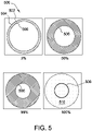
- Fig. 5 illustrates one example of an icon 500 for display on the Ul 416 to communicate to the patient 400 details about the coupling (i.e., coupling coefficient k) between the external coil 402 and the implanted coil 404 (all shown in Fig. 4 ).
- the progression of the icon 500 illustrated in Fig. 5 shows how the icon 500 communicates a progressive increase in the coupling to the patient 400.
- the icon 500 is represented as a circle 502.
- the icon 500 may be represented as a ring, a square, a filleted square, and/or any other shape.
- the icon 500 is represented as a shape with two-fold symmetry.
- the circular icon 500 has a fixed outer diameter 504 and a variable inner diameter 506.
- the inner diameter 506 shrinks, such that the icon 500 gives the patient 400 a sense of approaching a "bull's eye" as the coupling increases. In this way, the icon 500 makes it apparent to the patient 400 that they are "on the right track” in positioning the external coil 402.
- the inner diameter 506 shrinks continuously as the coupling increases. In this way, the icon 500 aids the patient 400 in achieving optimum accuracy in the positioning of the external coil 402.
- the inner diameter 506 shrinks in discrete increments.
- icon 500 also includes a textual indication (e.g., a displayed percentage) indicating the level of coupling.
- the inner diameter 506 "jumps" from its current size at the time of optimum coupling down to zero.
- the entire icon 500 is suddenly lit up. This is illustrated in Fig. 5 by the substantially filled icon 510 designated by " 100%.” In this way, the icon 500 gives the patient 400 substantially immediate feedback that the positioning of the external coil 402 is near optimum and gives the patient 400 confidence that the external coil 402 is sufficiently coupled to the implanted coil 404.
- the icon 500 is color-coded to provide additional information to the patient 400 regarding the status of the positioning of the external coil 402. This is illustrated in Fig. 5 with the single hatching of the icon 500 at "3%" of an optimal coupling, the single hatching representing, for example, a red color; the cross-hatching of the icon 500 at "50%” and “99%” representing, for example, a yellow color; and the dotted hatching of the filled icon 510 at "100%" representing, for example, a green color.
- the icon 500 may not be color-coded.
- an intensity of the icon 500 is varied to represent the status of the positioning of the external coil 402.
- the intensity of the icon 500 may increase as the coupling increases.
- the intensity of the icon 500 is maintained substantially constant.
- the user interface 416 may further include audio capability, such that the status of the coupling is represented using ascending tones (e.g., to represent increases in coupling) and/or descending tones (e.g., to represent decreases in coupling).
- the tones may additionally or alternatively pulse, and the frequency may indicate the status of the coupling.
- a continuous tone e.g., a continuous ascending tone
- a pulsing tone may indicate a decrease in the coupling.
- a sonic intensity may indicate the status of the coupling.
- the user interface 416 may further include a directional indicator (not shown), such as arrows, chevrons, dots, lines, curves, and/or other geometric shapes.
- the directional indicator may light up or activate to indicate to the patient 400 which direction to move the external coil 402 to increase the coupling with the implanted coil 404.
- the icon 500 When the coupling is increasing, as shown in Fig. 5 , the icon 500 includes a continuous circle 502. However, as shown in Fig. 6 , in this example, when the coupling is decreasing, the circle 502 becomes broken. Accordingly, the icon 500 quickly indicates to the patient 400 whether the coupling is currently increasing or decreasing, regardless of the immediate value of the coupling.
- Fig. 7 illustrates a first sigmoid curve 702 and a second sigmoid curve 704 that may control the rate at which the icon 500 changes.
- a center 706 of the first and second sigmoid curves 702 and 704 corresponds to the optimum coupling.
- Both sigmoid curves 702 and 704 include a planar segment 708 surrounding the center 706 that creates a forgiving "sweet spot". When the coupling falls within the planar segment 708, the filled icon 510 (shown in Fig. 5 ) is displayed.
- the first sigmoid curve 702 is a linear sigmoid curve
- the second sigmoid curve 704 is a relatively weak convex sigmoid curve. These curves 702 and 704 provide a good trade-off between registering a signal when the coils 402 and 404 are grossly misaligned and the final alignment accuracy.
- any suitable curve may be used to control the rate at which the icon 500 changes.
- planar segment 708 is not included in the sigmoid curve.
- the update/refresh rate of the Ul 416 can vary. That is, the update/refresh rate can be chosen based on typical coil movement speed during alignment, desired alignment accuracy, and the chosen icon/sigmoid combination. For example, the speed at which the patient 400 moves the coil may be approximately 1 meter per second (m/s).
- the magnetic sensor described herein assists a trained individual in locating an implant within a subject.
- the magnetic sensor may be used by an engineer to locate an implant within an animal, or may be used by a physician to locate an implant within a patient.
- the information gained from using the magnetic sensor may be used for analysis, not necessarily immediate action.
- a physician may use the magnetic sensor to detect migration of an implant over time for clinical decision-making, such as, to determine whether the implant is exerting pressure on a particular organ or if sutures holding the implant in place have failed. This may be helpful because typically no external coil is present when the trained individual (e.g., clinician) uses the magnetic sensor.
- the patient's physiology often changes over time which can affect the location of the implanted coil relative to the external coil. For example, the patient may lose or gain weight, in particularly fatty tissue between the implant and skin line.
- the information from the sensor can be used by the physician to make adjustments or other clinical decisions.
- Fig. 8 shows one example of a magnetic sensor array 800 that may be used to locate an implanted device that includes magnetic coils, such as, for example, implanted coil 404 (shown in Fig. 4 ).
- the magnetic sensor array 800 includes six magnetic sensors 802, 804, 806, 808, 810, 812.
- the magnetic sensors 802, 804, 806, 808, 810, 812 may include, for example, pick-up coils, Hall probes, MEMS-based magnetic field sensors, and/or any type of magnetic sensor.
- the magnetic sensors 802, 804, 806, 808, 810, 812 are mounted to a rigid platform 814.
- the rigid platform 814 may include, for example, plastic or another polymer.
- the magnetic sensors 802, 804, 806, 808, 810, 812 are mounted to a flexible platform 814.
- the flexible platform 814 can include KAPTON ® or other polyimide films, polyester films, or cloth, such as cotton cloth.
- the magnetic sensor array 800 may be incorporated into a garment (e.g., a belt or shirt) as long as the garment is stretched taut, such that the locations of the magnetic sensors 802, 804, 806, 808, 810, 812 are substantially well-defined.
- the magnetic sensors 802, 804, 806, 808, 810, 812 are free to move with respect to one another (e.g., when they are placed on a garment), it is possible (in the absence of other magnetic materials) to use the magnetic sensors 802, 804, 806, 808, 810, 812 to determine the location of each other if the magnetic sensors 802, 804, 806, 808, 810, 812 are pick-up coils or if each magnetic sensor 802, 804, 806, 808, 810, 812 is a Hall sensor with a small coil placed around it.
- energizing each coil and measuring the responses in the other coils creates a data set that uniquely defines the locations of all coils (e.g., relative to a one of the coils that is used as a reference coil). Between any two circular coils, there are four degrees of freedom. Accordingly, for a system of six coils, a system of equations for all locations and angles between the magnetic sensors 802, 804, 806, 808, 810, 812 is uniquely defined and solvable using, for example, the Biot-Savart calculations and/or finite element analysis techniques.
- the magnetic sensors 802, 804, 806, 808, 810, 812 are mounted to the platform 814 and can be interconnected using a flexible circuit or discrete cabling 816 to allow communications between the magnetic sensors 802, 804, 806, 808, 810, 812.
- the magnetic sensor array 800 can also include a connector 818 to, for example, an external power supply and/or an external computing device.
- the magnetic sensors 802, 804, 806, 808, 810, 812 are each connected to every other magnetic sensor 802, 804, 806, 808, 810, 812 with cabling 816, but it should be understood that the specific connection patterns can vary (e.g., in some arrangements the magnetic sensors 802, 804, 806, 808, 810, 812 may be coupled in series). Moreover, although the magnetic sensors 802, 804, 806, 808, 810, 812 are shown in a 2D array in this example, with each of the magnetic sensors 802, 804, 806, 808, 810, 812 having the same orientation, it should be understood that various other configurations may be implemented.
- the magnetic sensors 802, 804, 806, 808, 810, 812 may be arranged in a one-dimensional (ID) array (e.g., in series) or a 3D array.
- the magnetic sensors 802, 804, 806, 808, 810, 812 may be arranged such that one or more of the magnetic sensors 802, 804, 806, 808, 810, 812 are in one or more different planes and/or have one or more different orientations from the others of magnetic sensors 802, 804, 806, 808, 810, 812.
- the magnetic sensor array 800 may include more than six magnetic sensors.
- the pick-up coils for each magnetic sensors 802, 804, 806, 808, 810, 812 are be approximately 5 mm in diameter.
- the pick-up coils may have any suitable size.
- the pick-up coils may be as small as 1 mm in diameter.
- the active element in each magnetic sensor 802, 804, 806, 808, 810, 812 may be even smaller (e.g., dimensions on the order of fractions of a millimeter), but may include packaging on the millimeter scale to facilitate handling of the sensor.
- sensor size is determined by application. For example, if the goal is centimeter-scale precision, magnetic sensors 802, 804, 806, 808, 810, 812 can't be much larger than a centimeter.
- magnetic sensors 802, 804, 806, 808, 810, 812 may have any size that enables them to function as described herein. To improve precision in locating the implanted device, magnetic sensors 802, 804, 806, 808, 810, 812 may be spread evenly over an imagined sphere surrounding the implant. In contrast, if magnetic sensors 802, 804, 806, 808, 810, 812 are clustered together into a space that is small compared to a distance between magnetic sensors 802, 804, 806, 808, 810, 812 and the implanted device, precision will generally be poorer.
- the magnetic sensor array 800 measures a magnetic field generated by the implanted device. Based on the measured magnetic field, a computing device (also referred to as a position detection module) communicatively coupled to the magnetic sensor array 800 calculates the precise position of the implanted device relative to the magnetic sensor array 800. Further, the calculated position may be displayed on a display device and/or transmitted to another device. The calculated position may also be stored in a memory as position data. For example, the position data may be stored in association with subject data that is associated with the subject.
- the computing device may be external to the magnetic sensor array 800 or may be a microprocessor integrated within the magnetic sensor array 800.
- Fig. 9 illustrates a flow chart of one example of a method 900 for locating an implanted device.
- the method 900 may be performed, for example, using the magnetic sensor array 800 (shown in Fig. 8 ).
- the method 900 includes calibrating 902 the sensor array to create a database of sensor responses corresponding to various implant locations and orientations.
- the sensor responses may be stored, for example, in a memory.
- the calibration 902 may be based on a computer simulation or upon measurements taken relative to an actual implanted device.
- the calibrated sensor array is then positioned 904 proximate the subject (e.g., an animal or patient) near an expected location of the implanted device. Then, the implanted device is instructed 906 to power its magnetic coils for a predetermined period of time (e.g., a fraction of a second). While the magnetic coils are powered, the calibrated sensor array measures 908 the magnetic field generated by the implanted device. The measured magnetic field is transmitted 910 to a computing device, and the computing device calculates 912 the position of the implanted device based on the measured magnetic field. Specifically, in this example, the computing device calculates 912 the position of the implanted device by comparing the measured magnetic field with the sensor responses generated calibration 902 of the sensor array. The comparison may be made using a variety of data matching methods (e.g., least square fit) and interpolation techniques may be used to improve accuracy and/or reduce the size of the database.
- a predetermined period of time e.g., a fraction of a second.
- magnetic sensor array 800 may be used to detect migration of the implanted device over time.
- a position tracking module i.e., a computing device
- the position tracking module may store an initial position detected at a first time, and at least one subsequent position detected at a later time. By calculating the distance (if any) between the initial position and the at least one subsequent position, the position tracking module is able to determine how far the implanted device has migrated.
- a magnetic sensor array may be used to locate an implant having magnetic coils quickly and easily.
- the magnetic sensor array provides immediate feedback about the precise location of the implant, and does not require uncommon or rare equipment to operate.
- this disclosure can pertain to any device that receives power wirelessly at a distance from the power source, including all types of electronics (cell phones, portable computers, PDAs, mobile games, remote controls, etc.), electric cars, trains, and other vehicles, or any other device that uses electric power.
- the disclosure could be used to charge the batteries of any such device, or to power it directly.
- the disclosure does not rely on either the transmitter or receiver being in resonance, although it can take advantage of such systems.
Landscapes
- Engineering & Computer Science (AREA)
- Life Sciences & Earth Sciences (AREA)
- Health & Medical Sciences (AREA)
- Physics & Mathematics (AREA)
- Veterinary Medicine (AREA)
- Public Health (AREA)
- Biomedical Technology (AREA)
- Animal Behavior & Ethology (AREA)
- General Health & Medical Sciences (AREA)
- Remote Sensing (AREA)
- Power Engineering (AREA)
- General Physics & Mathematics (AREA)
- Nuclear Medicine, Radiotherapy & Molecular Imaging (AREA)
- Electromagnetism (AREA)
- Surgery (AREA)
- Human Computer Interaction (AREA)
- Computer Networks & Wireless Communication (AREA)
- Radiology & Medical Imaging (AREA)
- Heart & Thoracic Surgery (AREA)
- Molecular Biology (AREA)
- Medical Informatics (AREA)
- Pathology (AREA)
- General Life Sciences & Earth Sciences (AREA)
- Environmental & Geological Engineering (AREA)
- Geology (AREA)
- Geophysics (AREA)
- Biophysics (AREA)
- Acoustics & Sound (AREA)
- Oral & Maxillofacial Surgery (AREA)
- Condensed Matter Physics & Semiconductors (AREA)
- Electrotherapy Devices (AREA)
- Measuring And Recording Apparatus For Diagnosis (AREA)
Claims (13)
- Système de localisation d'un dispositif implanté (406) comprenant des bobines magnétiques (404) à l'intérieur d'un sujet (400), le système comprenant :un réseau de capteurs magnétiques (800) comprenant une pluralité de capteurs magnétiques (802, 804, 806, 808, 810, 812), le réseau de capteurs magnétiques (800) étant configuré pour mesurer un champ magnétique généré par le dispositif implanté (406) ; etun module de détection de position couplé en communication au réseau de capteurs magnétiques (800), le module de détection de position étant configuré pour :recevoir le champ magnétique mesuré à partir du réseau de capteurs magnétiques (800) ; etcalculer une position du dispositif implanté (406) sur la base du champ magnétique mesuré, caractérisé en ce quele système comprend en outre une plate-forme flexible (814) et la pluralité de capteurs magnétiques (802, 804, 806, 808, 810, 812) sont montés sur la plate-forme flexible (814), de telle sorte que les capteurs magnétiques sont libres de se déplacer les uns par rapport aux autres.
- Système selon la revendication 1, dans lequel le réseau de capteurs magnétiques (800) comprend six capteurs magnétiques (802, 804, 806, 808, 810, 812).
- Système selon la revendication 1, comprenant en outre un dispositif d'affichage (416) configuré pour afficher la position calculée à un utilisateur.
- Système selon la revendication 1, dans lequel le module de détection de position est configuré pour calibrer le réseau de capteurs magnétiques (800) en utilisant des mesures acquises à partir d'un implant réel.
- Système selon la revendication 1, dans lequel le module de détection de position est en outre configuré pour transmettre la position calculée à un autre dispositif.
- Système selon la revendication 1, comprenant en outre un module de suivi de position couplé en communication au réseau de capteurs magnétiques (800) et configuré pour :stocker une position initiale du dispositif implanté (406) ;stocker une position subséquente du dispositif implanté (406) ; etcalculer une distance entre la position initiale et la position suivante.
- Procédé localisation d'un dispositif implanté (406) comprenant des bobines magnétiques (404) à l'intérieur d'un sujet (400), le procédé comprenant les étapes consistant à :calibrer un réseau de capteurs magnétiques (800) pour créer une base de données de réponses de capteurs correspondant à divers emplacements et orientations d'implant, le réseau de capteurs magnétiques (800) comprenant une pluralité de capteurs magnétiques (802, 804, 806, 808, 810, 812) montés sur une plate-forme flexible (814) de telle sorte que les capteurs magnétiques sont libres de se déplacer les uns par rapport aux autres ;positionner le réseau de capteurs magnétiques (800) à proximité du sujet (400) près d'une position attendue du dispositif implanté (406) ;donner pour instruction au dispositif implanté (406) d'alimenter les bobines magnétiques (404) ;mesurer, à l'aide du réseau de capteurs magnétiques (800), un champ magnétique généré par le dispositif implanté (406) ;transmettre le champ magnétique mesuré à un module de détection de position ; etcalculer, à l'aide du module de détection de position, une position du dispositif implanté (406) sur la base du champ magnétique mesuré.
- Procédé selon la revendication 7, comprenant en outre l'étape consistant à délivrer en sortie la position calculée.
- Système selon la revendication 1, comprenant une bobine externe (402), le système comprenant en outre :un dispositif informatique (410) couplé en communication à la bobine externe (402), le dispositif informatique (410) comprenant une interface utilisateur (416) configurée pour afficher une icône (500) qui indique un degré de couplage entre la bobine externe (402) et une bobine implantée (404), dans lequel l'icône (500) est un cercle qui comprend un diamètre externe fixe (504) et un diamètre interne variable (506), dans lequelle diamètre interne variable (506) diminue lorsque le degré de couplage augmente, et dans lequel le diamètre interne variable (506) augmente lorsque le degré de couplage diminue.
- Système selon la revendication 9, dans lequel l'interface utilisateur (416) est configurée de telle sorte que le diamètre interne variable (506) change conformément à une courbe sigmoïde (702, 704).
- Système selon la revendication 10, dans lequel l'interface utilisateur (416) est configurée de telle sorte que la courbe sigmoïde (702, 704) soit l'une d'une courbe sigmoïde linéaire (702) et d'une courbe sigmoïde convexe (704).
- Système selon la revendication 9, dans lequel l'interface utilisateur (416) est configurée de telle sorte que le diamètre interne (506) diminue jusqu'à zéro lorsqu'un degré prédéterminé de couplage est atteint.
- Système selon la revendication 9, dans lequel l'interface utilisateur (416) est configurée de telle sorte qu'une couleur de l'icône (500) varie avec le degré de couplage.
Priority Applications (1)
| Application Number | Priority Date | Filing Date | Title |
|---|---|---|---|
| EP22177895.4A EP4084271A1 (fr) | 2016-09-21 | 2017-09-20 | Systèmes et procédés de localisation de dispositifs implantés de transmission de puissance sans fil |
Applications Claiming Priority (2)
| Application Number | Priority Date | Filing Date | Title |
|---|---|---|---|
| US201662397676P | 2016-09-21 | 2016-09-21 | |
| PCT/US2017/052406 WO2018057563A1 (fr) | 2016-09-21 | 2017-09-20 | Systèmes et procédés de localisation de dispositifs de transmission de puissance sans fil implantés |
Related Child Applications (2)
| Application Number | Title | Priority Date | Filing Date |
|---|---|---|---|
| EP22177895.4A Division EP4084271A1 (fr) | 2016-09-21 | 2017-09-20 | Systèmes et procédés de localisation de dispositifs implantés de transmission de puissance sans fil |
| EP22177895.4A Division-Into EP4084271A1 (fr) | 2016-09-21 | 2017-09-20 | Systèmes et procédés de localisation de dispositifs implantés de transmission de puissance sans fil |
Publications (2)
| Publication Number | Publication Date |
|---|---|
| EP3497775A1 EP3497775A1 (fr) | 2019-06-19 |
| EP3497775B1 true EP3497775B1 (fr) | 2022-07-13 |
Family
ID=60117742
Family Applications (2)
| Application Number | Title | Priority Date | Filing Date |
|---|---|---|---|
| EP17784720.9A Active EP3497775B1 (fr) | 2016-09-21 | 2017-09-20 | Systèmes et procédés de localisation de dispositifs de transmission de puissance sans fil implantés |
| EP22177895.4A Pending EP4084271A1 (fr) | 2016-09-21 | 2017-09-20 | Systèmes et procédés de localisation de dispositifs implantés de transmission de puissance sans fil |
Family Applications After (1)
| Application Number | Title | Priority Date | Filing Date |
|---|---|---|---|
| EP22177895.4A Pending EP4084271A1 (fr) | 2016-09-21 | 2017-09-20 | Systèmes et procédés de localisation de dispositifs implantés de transmission de puissance sans fil |
Country Status (3)
| Country | Link |
|---|---|
| US (2) | US10898292B2 (fr) |
| EP (2) | EP3497775B1 (fr) |
| WO (1) | WO2018057563A1 (fr) |
Families Citing this family (36)
| Publication number | Priority date | Publication date | Assignee | Title |
|---|---|---|---|---|
| DE102016209871A1 (de) | 2016-06-06 | 2017-12-07 | Robert Bosch Gmbh | Stanzvorrichtung und Verfahren zum Stanzen eines Lumens und Implantieren einer Implantateinrichtung |
| EP3634528B1 (fr) | 2017-06-07 | 2023-06-07 | Shifamed Holdings, LLC | Dispositifs de déplacement de fluide intravasculaire, systèmes et procédés d'utilisation |
| US11511103B2 (en) | 2017-11-13 | 2022-11-29 | Shifamed Holdings, Llc | Intravascular fluid movement devices, systems, and methods of use |
| WO2019135890A1 (fr) | 2018-01-04 | 2019-07-11 | Tc1 Llc | Systèmes et procédés de dispositifs de transmission d'énergie sans fil élastique |
| DE102018201030B4 (de) | 2018-01-24 | 2025-10-16 | Kardion Gmbh | Magnetkuppelelement mit magnetischer Lagerungsfunktion |
| EP3746149B1 (fr) | 2018-02-01 | 2025-08-06 | Shifamed Holdings, LLC | Pompes à sang intravasculaires |
| DE102018206750A1 (de) | 2018-05-02 | 2019-11-07 | Kardion Gmbh | Vorrichtung zur induktiven Energieübertragung in einen menschlichen Körper und deren Verwendung |
| DE102018206725A1 (de) | 2018-05-02 | 2019-11-07 | Kardion Gmbh | Empfangseinheit, Sendeeinheit, Energieübertragungssystem und Verfahren zur drahtlosen Energieübertragung |
| DE102018206754A1 (de) | 2018-05-02 | 2019-11-07 | Kardion Gmbh | Verfahren und Vorrichtung zur Bestimmung der Temperatur an einer Oberfläche sowie Verwendung des Verfahrens |
| DE102018206727A1 (de) | 2018-05-02 | 2019-11-07 | Kardion Gmbh | Energieübertragungssystem und Empfangseinheit zur drahtlosen transkutanen Energieübertragung |
| DE102018206731A1 (de) | 2018-05-02 | 2019-11-07 | Kardion Gmbh | Vorrichtung zur induktiven Energieübertragung in einen menschlichen Körper und Verwendung der Vorrichtung |
| DE102018206724A1 (de) | 2018-05-02 | 2019-11-07 | Kardion Gmbh | Energieübertragungssystem und Verfahren zur drahtlosen Energieübertragung |
| DE102018208539A1 (de) | 2018-05-30 | 2019-12-05 | Kardion Gmbh | Motorgehäusemodul zum Abdichten eines Motorraums eines Motors eines Herzunterstützungssystems und Herzunterstützungssystem und Verfahren zum Montieren eines Herzunterstützungssystems |
| DE102018208549A1 (de) | 2018-05-30 | 2019-12-05 | Kardion Gmbh | Elektronikmodul für ein Herzunterstützungssystem und Verfahren zum Herstellen eines Elektronikmoduls für ein Herzunterstützungssystem |
| DE102018208555A1 (de) | 2018-05-30 | 2019-12-05 | Kardion Gmbh | Vorrichtung zum Verankern eines Herzunterstützungssystems in einem Blutgefäß, Verfahren zum Betreiben und Herstellverfahren zum Herstellen einer Vorrichtung und Herzunterstützungssystem |
| EP3583892A1 (fr) * | 2018-06-20 | 2019-12-25 | Koninklijke Philips N.V. | Unité de détection de pression, système et procédé de détection de pression à distance |
| DE102018211185A1 (de) * | 2018-07-06 | 2020-01-09 | Neuroloop GmbH | Vorrichtung zur transkutanen Lokalisation eines intrakorporal, subkutan verorteten medizinischen Implantats |
| WO2020028537A1 (fr) | 2018-07-31 | 2020-02-06 | Shifamed Holdings, Llc | Pompes sanguines intravasculaires et procédés d'utilisation |
| WO2020073047A1 (fr) | 2018-10-05 | 2020-04-09 | Shifamed Holdings, Llc | Pompes à sang intravasculaires et procédés d'utilisation |
| WO2021011473A1 (fr) | 2019-07-12 | 2021-01-21 | Shifamed Holdings, Llc | Pompes à sang intravasculaires et méthode d'utilisation et procédé de fabrication |
| US11654275B2 (en) | 2019-07-22 | 2023-05-23 | Shifamed Holdings, Llc | Intravascular blood pumps with struts and methods of use and manufacture |
| US12465748B2 (en) | 2019-08-07 | 2025-11-11 | Supira Medical, Inc. | Catheter blood pumps and collapsible pump housings |
| WO2021062260A1 (fr) | 2019-09-25 | 2021-04-01 | Shifamed Holdings, Llc | Pompes à sang de cathéter et conduits sanguins pliables |
| EP4501393A3 (fr) | 2019-09-25 | 2025-04-09 | Shifamed Holdings, LLC | Pompes à sang à cathéter et boîtiers de pompes pliables |
| US11724089B2 (en) | 2019-09-25 | 2023-08-15 | Shifamed Holdings, Llc | Intravascular blood pump systems and methods of use and control thereof |
| EP3833050B1 (fr) | 2019-12-06 | 2026-01-28 | GN Hearing A/S | Procédé de chargement d'une batterie d'un dispositif auditif |
| US12102817B2 (en) * | 2019-12-10 | 2024-10-01 | Medtronic, Inc. | Method for determining coupling coefficient for wireless power transfer |
| EP4072650A4 (fr) | 2019-12-11 | 2024-01-10 | Shifamed Holdings, LLC | Pompes à sang d'aorte descendante et de veine cave |
| EP4077947A4 (fr) | 2019-12-19 | 2024-01-10 | Shifamed Holdings, LLC | Pompes à sang intravasculaires, moteurs et commande de fluide |
| CN116157058B (zh) | 2020-07-21 | 2025-08-12 | 德普伊新特斯产品公司 | 骨固定监测系统 |
| US11699551B2 (en) | 2020-11-05 | 2023-07-11 | Kardion Gmbh | Device for inductive energy transmission in a human body and use of the device |
| US20240033533A1 (en) * | 2020-12-23 | 2024-02-01 | Solenic Medical, Inc. | System for application of alternating magnetic fields to reduce infection |
| US11744583B2 (en) * | 2021-02-26 | 2023-09-05 | Cilag Gmbh International | Distal communication array to tune frequency of RF systems |
| US12458292B2 (en) | 2021-07-16 | 2025-11-04 | DePuy Synthes Products, Inc. | Smart plate sensors |
| US12408844B2 (en) | 2022-04-05 | 2025-09-09 | Senseonics, Incorporated | Implant finder |
| WO2024102399A1 (fr) * | 2022-11-11 | 2024-05-16 | Shiratronics, Inc. | Systèmes de surveillance de systèmes de dispositif multi-implantable |
Citations (1)
| Publication number | Priority date | Publication date | Assignee | Title |
|---|---|---|---|---|
| US20120262108A1 (en) * | 2011-04-18 | 2012-10-18 | Medtronic, Inc. | Recharge tuning techniques for an implantable device |
Family Cites Families (317)
| Publication number | Priority date | Publication date | Assignee | Title |
|---|---|---|---|---|
| US4041955A (en) | 1976-01-29 | 1977-08-16 | Pacesetter Systems Inc. | Implantable living tissue stimulator with an improved hermetic metal container |
| US4222374A (en) * | 1978-06-16 | 1980-09-16 | Metal Bellows Corporation | Septum locating apparatus |
| US4352960A (en) | 1980-09-30 | 1982-10-05 | Baptist Medical Center Of Oklahoma, Inc. | Magnetic transcutaneous mount for external device of an associated implant |
| US4561444A (en) | 1981-08-10 | 1985-12-31 | Cordis Corporation | Implantable cardiac pacer having dual frequency programming and bipolar/linipolar lead programmability |
| US4561443A (en) | 1983-03-08 | 1985-12-31 | The Johns Hopkins University | Coherent inductive communications link for biomedical applications |
| US4630615A (en) | 1984-05-21 | 1986-12-23 | Cordis Corporation | Apparatus for measuring impedance |
| US4679560A (en) | 1985-04-02 | 1987-07-14 | Board Of Trustees Of The Leland Stanford Junior University | Wide band inductive transdermal power and data link |
| US4726378A (en) | 1986-04-11 | 1988-02-23 | Minnesota Mining And Manufacturing Company | Adjustable magnetic supercutaneous device and transcutaneous coupling apparatus |
| US4736747A (en) | 1986-04-11 | 1988-04-12 | Minnesota Mining And Manufacturing Company | Adjustable magnetic supercutaneous device and transcutaneous coupling apparatus |
| US4945305A (en) | 1986-10-09 | 1990-07-31 | Ascension Technology Corporation | Device for quantitatively measuring the relative position and orientation of two bodies in the presence of metals utilizing direct current magnetic fields |
| JP2597623B2 (ja) | 1987-10-08 | 1997-04-09 | 株式会社トキメック | 電磁誘導結合による電源供給方式 |
| US5070223A (en) | 1989-03-01 | 1991-12-03 | Colasante David A | Microwave reheatable clothing and toys |
| JPH03109063A (ja) | 1989-09-22 | 1991-05-09 | Tanaka Kikinzoku Kogyo Kk | コネクター |
| US5350413B1 (en) | 1990-06-21 | 1999-09-07 | Heart Inst Research Corp | Transcutaneous energy transfer device |
| DE4020120A1 (de) | 1990-06-25 | 1991-01-31 | Klaus Prof Dr Ing Affeld | Medizinische vorrichtung zur erzeugung eines alternierenden volumenstroms fuer den antrieb von implantierbaren blutpumpen |
| US5425367A (en) * | 1991-09-04 | 1995-06-20 | Navion Biomedical Corporation | Catheter depth, position and orientation location system |
| US5146933A (en) * | 1991-09-20 | 1992-09-15 | Dow Corning Wright Corporation | Implantable prosthetic device and tethered inflation valve for volume |
| AU4626893A (en) | 1992-09-14 | 1994-03-24 | Aprex Corporation | Contactless communication system |
| DE69419420T2 (de) | 1993-09-10 | 1999-11-18 | Ottawa Heart Institute Research Corp., Ottawa | Elektrohydraulisches ventrikulares unterstützungssystem |
| US5630836A (en) | 1995-01-19 | 1997-05-20 | Vascor, Inc. | Transcutaneous energy and information transmission apparatus |
| ATE255300T1 (de) | 1995-05-18 | 2003-12-15 | Aura Communications Inc | Magnetische kommunikationssystem mit geringer reichweite |
| US5702431A (en) | 1995-06-07 | 1997-12-30 | Sulzer Intermedics Inc. | Enhanced transcutaneous recharging system for battery powered implantable medical device |
| US5690693A (en) | 1995-06-07 | 1997-11-25 | Sulzer Intermedics Inc. | Transcutaneous energy transmission circuit for implantable medical device |
| JP3224508B2 (ja) | 1996-05-23 | 2001-10-29 | シャープ株式会社 | 加熱制御装置 |
| US5755748A (en) | 1996-07-24 | 1998-05-26 | Dew Engineering & Development Limited | Transcutaneous energy transfer device |
| US5733313A (en) | 1996-08-01 | 1998-03-31 | Exonix Corporation | RF coupled, implantable medical device with rechargeable back-up power source |
| US7107103B2 (en) | 1997-02-26 | 2006-09-12 | Alfred E. Mann Foundation For Scientific Research | Full-body charger for battery-powered patient implantable device |
| WO1999004834A1 (fr) | 1997-07-25 | 1999-02-04 | Sun Medical Technology Research Corporation | Systeme de commande portable pour coeur artificiel |
| AU9787498A (en) | 1997-10-02 | 1999-04-27 | Micromed Technology, Inc. | Implantable pump system |
| US6138681A (en) * | 1997-10-13 | 2000-10-31 | Light Sciences Limited Partnership | Alignment of external medical device relative to implanted medical device |
| WO2002039917A1 (fr) | 1998-05-14 | 2002-05-23 | Calypso Medical, Inc. | Systemes et procedes de localisation et definition d'une cible interieure au corps humain |
| US6389318B1 (en) | 1998-07-06 | 2002-05-14 | Abiomed, Inc. | Magnetic shield for primary coil of transcutaneous energy transfer device |
| US8489200B2 (en) | 1998-07-06 | 2013-07-16 | Abiomed, Inc. | Transcutaneous energy transfer module with integrated conversion circuitry |
| US6324431B1 (en) | 1998-07-06 | 2001-11-27 | Abiomed, Inc. | Transcutaneous energy transfer device with magnetic field protected components in secondary coil |
| US6634364B2 (en) | 2000-12-15 | 2003-10-21 | Cardiac Pacemakers, Inc. | Method of deploying a ventricular lead containing a hemostasis mechanism |
| US6296533B1 (en) | 1998-08-31 | 2001-10-02 | The Whitaker Corporation | Electrical receptacle contact |
| US6149683A (en) | 1998-10-05 | 2000-11-21 | Kriton Medical, Inc. | Power system for an implantable heart pump |
| US5948006A (en) | 1998-10-14 | 1999-09-07 | Advanced Bionics Corporation | Transcutaneous transmission patch |
| US6312338B1 (en) | 1998-10-21 | 2001-11-06 | Nintendo Company, Ltd. | Electronic accessory for game machine |
| US6212430B1 (en) | 1999-05-03 | 2001-04-03 | Abiomed, Inc. | Electromagnetic field source with detection of position of secondary coil in relation to multiple primary coils |
| US6146325A (en) | 1999-06-03 | 2000-11-14 | Arrow International, Inc. | Ventricular assist device |
| US7522878B2 (en) | 1999-06-21 | 2009-04-21 | Access Business Group International Llc | Adaptive inductive power supply with communication |
| US6553263B1 (en) | 1999-07-30 | 2003-04-22 | Advanced Bionics Corporation | Implantable pulse generators using rechargeable zero-volt technology lithium-ion batteries |
| US6442434B1 (en) | 1999-10-19 | 2002-08-27 | Abiomed, Inc. | Methods and apparatus for providing a sufficiently stable power to a load in an energy transfer system |
| WO2001037926A1 (fr) | 1999-11-22 | 2001-05-31 | Abiomed, Inc. | Appareil pour le transfert d'energie au-dela d'une limite |
| US8155752B2 (en) | 2000-03-17 | 2012-04-10 | Boston Scientific Neuromodulation Corporation | Implantable medical device with single coil for charging and communicating |
| US6895281B1 (en) | 2000-03-31 | 2005-05-17 | Cardiac Pacemakers, Inc. | Inductive coil apparatus for bio-medical telemetry |
| AU3949800A (en) | 2000-04-20 | 2001-11-07 | Cochlear Limited | Transcutaneous power optimization circuit for cochlear implant |
| US6579315B1 (en) | 2000-04-25 | 2003-06-17 | The Penn State Research Foundation | Artificial heart power supply system |
| US6451055B1 (en) | 2000-04-25 | 2002-09-17 | The Penn State Research Foundation | Artificial heart data communication system |
| US6458164B1 (en) | 2000-04-25 | 2002-10-01 | The Penn State Research Foundation | Artificial heart with energy recovery |
| US6478820B1 (en) | 2000-04-25 | 2002-11-12 | The Penn State Research Foundation | Artificial heart with synchronous rectification |
| US7167756B1 (en) | 2000-04-28 | 2007-01-23 | Medtronic, Inc. | Battery recharge management for an implantable medical device |
| US6327504B1 (en) | 2000-05-10 | 2001-12-04 | Thoratec Corporation | Transcutaneous energy transfer with circuitry arranged to avoid overheating |
| WO2001095432A1 (fr) | 2000-06-02 | 2001-12-13 | Yamatake Corporation | Dispositif de liaison a induction electromagnetique |
| US6850803B1 (en) | 2000-06-16 | 2005-02-01 | Medtronic, Inc. | Implantable medical device with a recharging coil magnetic shield |
| DE60140025D1 (de) | 2000-06-19 | 2009-11-12 | Medtronic Inc | Implantierbares medizinisches Gerät mit einer externen Nachladespule |
| US6320354B1 (en) | 2000-07-21 | 2001-11-20 | Motorola, Inc. | Method and apparatus for battery charging |
| US6591139B2 (en) | 2000-09-06 | 2003-07-08 | Advanced Bionics Corporation | Low-power, high-modulation-index amplifier for use in battery-powered device |
| JP2002185238A (ja) | 2000-12-11 | 2002-06-28 | Sony Corp | デュアルバンド対応内蔵アンテナ装置およびこれを備えた携帯無線端末 |
| US20020087204A1 (en) | 2001-01-04 | 2002-07-04 | Kung Robert T. V. | Flexible transcutaneous energy transfer (TET) primary coil |
| SE0100284D0 (sv) | 2001-01-31 | 2001-01-31 | St Jude Medical | Medical communication system |
| US7532901B1 (en) | 2001-03-16 | 2009-05-12 | Radeum, Inc. | Methods and apparatus to detect location and orientation in an inductive system |
| US7142811B2 (en) | 2001-03-16 | 2006-11-28 | Aura Communications Technology, Inc. | Wireless communication over a transducer device |
| DE10119691A1 (de) | 2001-04-20 | 2002-11-21 | Deutsch Zentr Luft & Raumfahrt | System zum Unterstützen des linken Herzventrikels |
| US7126310B1 (en) | 2001-04-20 | 2006-10-24 | Abiomed, Inc. | Apparatus and method for balanced charging of a multiple-cell battery pack |
| US6723039B2 (en) | 2001-04-27 | 2004-04-20 | The Foundry, Inc. | Methods, systems and devices relating to implantable fluid pumps |
| KR100606307B1 (ko) | 2001-05-23 | 2006-07-28 | 안태영 | 인체 이식 기구용 무접촉식 동력 전달 장치 |
| US6647298B2 (en) | 2001-06-04 | 2003-11-11 | St. Jude Medical Ab | Implantable medical device with variable incoming communication signal discrimination, and method for operating same |
| US6894456B2 (en) | 2001-11-07 | 2005-05-17 | Quallion Llc | Implantable medical power module |
| US6985773B2 (en) | 2002-02-07 | 2006-01-10 | Cardiac Pacemakers, Inc. | Methods and apparatuses for implantable medical device telemetry power management |
| US7565187B1 (en) | 2002-04-11 | 2009-07-21 | Radeum, Inc. | Transceiver device and fastener |
| JP3731881B2 (ja) | 2002-05-23 | 2006-01-05 | 有限会社ティーエム | 人工臓器用非侵襲式充電システム、並びにこのシステムに用いる蓄電装置、および給電装置 |
| US7015769B2 (en) | 2002-06-20 | 2006-03-21 | Alfred E. Mann Foundation For Scientific Research | System and method for automatic tuning of a magnetic field generator |
| US7515012B2 (en) | 2002-06-20 | 2009-04-07 | Alfred E. Mann Foundation For Scientific Research | System and method for automatic tuning of a magnetic field generator |
| US6960968B2 (en) | 2002-06-26 | 2005-11-01 | Koninklijke Philips Electronics N.V. | Planar resonator for wireless power transfer |
| AU2003279616A1 (en) | 2002-06-28 | 2004-01-19 | Advanced Bionics Corporation | Microstimulator having self-contained power source and bi-directional telemetry system |
| US7428438B2 (en) | 2002-06-28 | 2008-09-23 | Boston Scientific Neuromodulation Corporation | Systems and methods for providing power to a battery in an implantable stimulator |
| US6772011B2 (en) | 2002-08-20 | 2004-08-03 | Thoratec Corporation | Transmission of information from an implanted medical device |
| AU2003263710B2 (en) | 2002-09-20 | 2008-08-14 | Implantica Patent Ltd. | Harmless wireless energy transmission to implant |
| DE10327500B4 (de) | 2003-06-17 | 2007-03-15 | W.C. Heraeus Gmbh | Verfahren zur Herstellung von Elektrodenstrukturen sowie Elektrodenstruktur und deren Verwendung |
| TWI257543B (en) | 2003-07-02 | 2006-07-01 | Delta Electronics Inc | Equalizing temperature device |
| US7818036B2 (en) | 2003-09-19 | 2010-10-19 | Radeum, Inc. | Techniques for wirelessly controlling push-to-talk operation of half-duplex wireless device |
| US7818037B2 (en) | 2003-09-19 | 2010-10-19 | Radeum, Inc. | Techniques for wirelessly controlling push-to-talk operation of half-duplex wireless device |
| US7225032B2 (en) | 2003-10-02 | 2007-05-29 | Medtronic Inc. | External power source, charger and system for an implantable medical device having thermal characteristics and method therefore |
| US20050075696A1 (en) | 2003-10-02 | 2005-04-07 | Medtronic, Inc. | Inductively rechargeable external energy source, charger, system and method for a transcutaneous inductive charger for an implantable medical device |
| US7286880B2 (en) | 2003-10-02 | 2007-10-23 | Medtronic, Inc. | System and method for transcutaneous energy transfer achieving high efficiency |
| US8265770B2 (en) | 2003-10-02 | 2012-09-11 | Medtronic, Inc. | Driver circuitry switchable between energy transfer and telemetry for an implantable medical device |
| US8140168B2 (en) | 2003-10-02 | 2012-03-20 | Medtronic, Inc. | External power source for an implantable medical device having an adjustable carrier frequency and system and method related therefore |
| DE10353943B4 (de) | 2003-11-18 | 2013-01-03 | Deutsches Zentrum für Luft- und Raumfahrt e.V. | Anordnung zur drahtlosen Energieübertragung an eine implantierte Einrichtung |
| JP4198045B2 (ja) * | 2003-12-25 | 2008-12-17 | オリンパス株式会社 | 被検体内位置検出システム |
| US7471986B2 (en) | 2004-02-20 | 2008-12-30 | Cardiac Pacemakers, Inc. | System and method for transmitting energy to and establishing a communications network with one or more implanted devices |
| US6967621B1 (en) | 2004-03-16 | 2005-11-22 | The United States Of America As Represented By The Secretary Of The Army | Small low profile antennas using high impedance surfaces and high permeability, high permittivity materials |
| US7571007B2 (en) | 2004-04-12 | 2009-08-04 | Advanced Neuromodulation Systems, Inc. | Systems and methods for use in pulse generation |
| US7212110B1 (en) | 2004-04-19 | 2007-05-01 | Advanced Neuromodulation Systems, Inc. | Implantable device and system and method for wireless communication |
| US7325124B2 (en) | 2004-04-21 | 2008-01-29 | International Business Machines Corporation | System and method of execution of register pointer instructions ahead of instruction issue |
| US20070222426A1 (en) | 2004-05-04 | 2007-09-27 | Koninklijke Philips Electronics, N.V. | Wireless Powering Device, an Energiable Load, a Wireless System and a Method For a Wireless Energy Transfer |
| US7599743B2 (en) | 2004-06-24 | 2009-10-06 | Ethicon Endo-Surgery, Inc. | Low frequency transcutaneous energy transfer to implanted medical device |
| WO2006014687A1 (fr) | 2004-07-20 | 2006-02-09 | Medtronic, Inc. | Telemetrie faisant appel a la puissance commutee dans un dispositif medical implantable |
| US20060030771A1 (en) * | 2004-08-03 | 2006-02-09 | Lewis Levine | System and method for sensor integration |
| EP1794848A4 (fr) | 2004-08-27 | 2010-11-24 | Pmi Ind Inc | Connecteur souple pour cablage electrique implantable |
| US8050738B2 (en) * | 2004-08-30 | 2011-11-01 | Olympus Corporation | Position detecting apparatus using the magnetic field direction of the earth's magnetic field |
| ATE443846T1 (de) | 2004-09-15 | 2009-10-15 | Deutsch Zentr Luft & Raumfahrt | Verarbeitung von fernerkundungsdaten |
| US7720546B2 (en) | 2004-09-30 | 2010-05-18 | Codman Neuro Sciences Sárl | Dual power supply switching circuitry for use in a closed system |
| EP1812094B1 (fr) | 2004-11-16 | 2011-08-17 | Micromed Technology, Inc. | Appareil de surveillance à distance des données pour système de pompe cardiaque |
| US8419609B2 (en) | 2005-10-05 | 2013-04-16 | Heartware Inc. | Impeller for a rotary ventricular assist device |
| US7699770B2 (en) | 2005-02-24 | 2010-04-20 | Ethicon Endo-Surgery, Inc. | Device for non-invasive measurement of fluid pressure in an adjustable restriction device |
| EP1880328A1 (fr) | 2005-04-11 | 2008-01-23 | Disetronic Licensing AG | Dispositif medical portable exploitable sur le web |
| US7505816B2 (en) | 2005-04-29 | 2009-03-17 | Medtronic, Inc. | Actively cooled external energy source, external charger, system of transcutaneous energy transfer, system of transcutaneous charging and method therefore |
| US7774069B2 (en) | 2005-04-29 | 2010-08-10 | Medtronic, Inc. | Alignment indication for transcutaneous energy transfer |
| WO2006121835A1 (fr) | 2005-05-06 | 2006-11-16 | Medtronic, Inc. | Dispositif implantable comportant un materiau d'absorption de chaleur |
| US7869858B2 (en) | 2005-05-12 | 2011-01-11 | General Electric Company | Patient table system and apparatus |
| US8112157B2 (en) | 2005-05-27 | 2012-02-07 | California Institute Of Technology | Magnetic material-containing microfabricated devices for wireless data and power transfer |
| US7825543B2 (en) | 2005-07-12 | 2010-11-02 | Massachusetts Institute Of Technology | Wireless energy transfer |
| KR101136889B1 (ko) | 2005-07-12 | 2012-04-20 | 메사추세츠 인스티튜트 오브 테크놀로지 | 무선 비-방사성 에너지 전달 |
| FR2889917A1 (fr) | 2005-09-01 | 2007-03-02 | Ela Medical Soc Par Actions Si | Equipement de telemetrie pour communiquer avec un dispositif actif implante dans une region du thorax d'un patient |
| US8792978B2 (en) | 2010-05-28 | 2014-07-29 | Lockheed Martin Corporation | Laser-based nerve stimulators for, E.G., hearing restoration in cochlear prostheses and method |
| US7590451B2 (en) | 2005-10-31 | 2009-09-15 | Medtronic, Inc. | Axial lead connector for implantable medical devices |
| WO2007053881A1 (fr) | 2005-11-08 | 2007-05-18 | Ventrassist Pty Ltd | Ameliorations des systemes de commande et des systemes de puissance destines a des pompes a sang rotatives |
| US7761164B2 (en) | 2005-11-30 | 2010-07-20 | Medtronic, Inc. | Communication system for medical devices |
| US7650192B2 (en) | 2005-12-02 | 2010-01-19 | Medtronic, Inc. | Passive charge of implantable medical device utilizing external power source and method |
| ES2349480T3 (es) | 2005-12-07 | 2011-01-04 | Boston Scientific Neuromodulation Corporation | Protección de pilas y baterías y sistema de reactivación de pilas y baterías con tensión nula para dispositivo médico implantable. |
| US20070142696A1 (en) | 2005-12-08 | 2007-06-21 | Ventrassist Pty Ltd | Implantable medical devices |
| DE102005059423A1 (de) | 2005-12-13 | 2007-06-21 | Airbus Deutschland Gmbh | Verfahren und Einrichtung zur redundanten Versorgung von mehreren elektrischen Stell-oder Antriebsmotoren durch eine gemeinsame Leistungselektronikeinheit |
| WO2008066941A2 (fr) | 2006-03-31 | 2008-06-05 | University Of Pittsburgh-Of The Commonwealth System Of Higher Education | Appareil portable qui délivre une alimentation et des informations à des dispositifs implantables |
| JP4914634B2 (ja) * | 2006-04-19 | 2012-04-11 | オリンパスメディカルシステムズ株式会社 | カプセル型医療装置 |
| JP4890953B2 (ja) | 2006-06-13 | 2012-03-07 | オリンパス株式会社 | カプセル内視鏡システム |
| US8103354B2 (en) | 2006-07-17 | 2012-01-24 | Advanced Bionics, Llc | Systems and methods for determining a threshold current level required to evoke a stapedial muscle reflex |
| DE102006035547A1 (de) | 2006-07-27 | 2008-02-21 | Deutsches Zentrum für Luft- und Raumfahrt e.V. | Übertragungs-Anordnung |
| US8159090B2 (en) | 2006-09-01 | 2012-04-17 | Powercast Corporation | Hybrid power harvesting and method |
| DE102006045928A1 (de) | 2006-09-28 | 2008-04-03 | Robert Bosch Gmbh | Anschlusssystem mit außenliegender Leitungsführung an Wischermotorgehäusen |
| EP2082468A2 (fr) | 2006-10-26 | 2009-07-29 | Koninklijke Philips Electronics N.V. | Revêtement de sol et système d'alimentation par induction |
| US7365542B1 (en) | 2006-10-31 | 2008-04-29 | General Electric Company | Flexible RF coil assembly and method of making same |
| US8330414B2 (en) | 2006-11-08 | 2012-12-11 | Panasonic Corporation | Contactless battery charger, electronic device, battery pack, and contactless charging system |
| US8096954B2 (en) | 2006-11-29 | 2012-01-17 | Cardiac Pacemakers, Inc. | Adaptive sampling of heart sounds |
| KR100836536B1 (ko) | 2006-12-21 | 2008-06-10 | 한국과학기술원 | 컨덕터의 안테나에 대한 영향이 감소된 에스아이피 및 그설계 방법 |
| US20080167531A1 (en) | 2007-01-05 | 2008-07-10 | Cardiac Pacemakers, Inc. | System and method to monitor battery status in an implantable medical device |
| US7792588B2 (en) | 2007-01-26 | 2010-09-07 | Medtronic, Inc. | Radio frequency transponder based implantable medical system |
| US8378522B2 (en) | 2007-03-02 | 2013-02-19 | Qualcomm, Incorporated | Maximizing power yield from wireless power magnetic resonators |
| US9774086B2 (en) | 2007-03-02 | 2017-09-26 | Qualcomm Incorporated | Wireless power apparatus and methods |
| US7932696B2 (en) | 2007-05-14 | 2011-04-26 | Boston Scientific Neuromodulation Corporation | Charger alignment indicator with adjustable threshold |
| US7830114B2 (en) | 2007-06-14 | 2010-11-09 | Visteon Global Technologies, Inc. | Flex circuit interface for wireless charging |
| US7812481B2 (en) | 2007-06-29 | 2010-10-12 | Seiko Epson Corporation | Power transmission control device, power transmission device, electronic instrument, and non-contact power transmission system |
| JP2010535392A (ja) | 2007-08-02 | 2010-11-18 | ユニバーシティ オブ ピッツバーグ オブ ザ コモンウェルス システム オブ ハイヤー エデュケーション | 複数の電子デバイスを有し、構築及び整合が簡素化されたワイヤレスシステム及び関連する方法 |
| US11581918B2 (en) | 2007-08-08 | 2023-02-14 | Freelinc Technologies Inc. | Near field communications system having enhanced security |
| JP5697979B2 (ja) | 2007-08-09 | 2015-04-08 | クゥアルコム・インコーポレイテッドQualcomm Incorporated | ワイヤレスに電力供給および充電するためのシステムおよび方法 |
| WO2009023905A1 (fr) | 2007-08-17 | 2009-02-26 | Ventrassist Pty Ltd | Ensembles et systèmes de bobines de transfert d'énergie transcutané |
| GB0716679D0 (en) | 2007-08-28 | 2007-10-03 | Fells J | Inductive power supply |
| ES2611597T3 (es) | 2007-09-06 | 2017-05-09 | Smith & Nephew, Inc. | Sistema y método para comunicar con un implante telemétrico |
| EP2188867A4 (fr) | 2007-09-13 | 2014-12-10 | Qualcomm Inc | Antenne pour applications d'électricité sans fil |
| JP2010539857A (ja) | 2007-09-17 | 2010-12-16 | クゥアルコム・インコーポレイテッド | ワイヤレスエネルギー伝送のための送信機および受信機 |
| CA2700991A1 (fr) | 2007-09-26 | 2009-04-02 | Radeum, Inc. Dba Freelinc | Systeme et procede de communications en champ proche presentant une securite locale |
| WO2009051538A1 (fr) | 2007-10-16 | 2009-04-23 | Milux Holding Sa | Procédé et appareil permettant de fournir de l'énergie à un dispositif médical |
| CN101896224B (zh) | 2007-10-16 | 2014-03-12 | 米卢克斯控股股份有限公司 | 一种向医疗设备供应能量的装置 |
| US8244367B2 (en) | 2007-10-26 | 2012-08-14 | Medtronic, Inc. | Closed loop long range recharging |
| WO2009055203A1 (fr) | 2007-10-26 | 2009-04-30 | Medtronic, Inc. | Procédé et appareil pour un ajustement dynamique de paramètres de recharge |
| WO2009070195A1 (fr) | 2007-11-27 | 2009-06-04 | Extremely Ingenious Engineering, Llc | Procédés et systèmes pour transmission d'énergie et de données sans fil |
| CA2709860A1 (fr) | 2007-12-21 | 2009-07-02 | Access Business Group International Llc | Transfert de puissance inductif |
| KR101061661B1 (ko) | 2008-01-09 | 2011-09-01 | 세이코 엡슨 가부시키가이샤 | 송전 제어 장치, 송전 장치, 무접점 전력 전송 시스템, 전자 기기 및 송전 제어 방법 |
| NZ565234A (en) | 2008-01-18 | 2010-11-26 | Telemetry Res Ltd | Selectable resonant frequency transcutaneous energy transfer system |
| US8165694B2 (en) | 2008-01-29 | 2012-04-24 | Boston Scientific Neuromodulation Corporation | Thermal management of implantable medical devices |
| CA2715916A1 (fr) | 2008-02-22 | 2009-08-27 | David W. Baarman | Systeme d'alimentation en puissance inductive equipe d'une fonction de detection de type de batterie |
| ES2556269T3 (es) | 2008-04-03 | 2016-01-14 | Koninklijke Philips N.V. | Sistema inalámbrico de transmisión de energía |
| US8150529B2 (en) | 2008-04-16 | 2012-04-03 | Pacesetter, Inc. | Medical devices and systems having separate power sources for enabling different telemetry systems |
| JP2009268181A (ja) | 2008-04-22 | 2009-11-12 | Olympus Corp | エネルギー供給装置 |
| US9526407B2 (en) | 2008-04-25 | 2016-12-27 | Karl Storz Imaging, Inc. | Wirelessly powered medical devices and instruments |
| US8193766B2 (en) | 2008-04-30 | 2012-06-05 | Medtronic, Inc. | Time remaining to charge an implantable medical device, charger indicator, system and method therefore |
| US8081925B2 (en) | 2008-05-08 | 2011-12-20 | Boston Scientific Neuromodulation Corporation | Transceiver for an implantable medical device having switchable series-to-parallel tank circuit |
| US9130407B2 (en) | 2008-05-13 | 2015-09-08 | Qualcomm Incorporated | Signaling charging in wireless power environment |
| JP4698702B2 (ja) | 2008-05-22 | 2011-06-08 | 三菱電機株式会社 | 電子機器 |
| ES2388219T3 (es) | 2008-06-02 | 2012-10-10 | F. Hoffmann-La Roche Ag | Purificación mejorada de colagenasas a partir de un cultivo líquido de Clostridium histolyticum |
| US20100019985A1 (en) | 2008-07-24 | 2010-01-28 | Jacob Bashyam | Header with integral antenna for implantable medical devices |
| US8278784B2 (en) | 2008-07-28 | 2012-10-02 | Qualcomm Incorporated | Wireless power transmission for electronic devices |
| US7893564B2 (en) | 2008-08-05 | 2011-02-22 | Broadcom Corporation | Phased array wireless resonant power delivery system |
| US8111042B2 (en) | 2008-08-05 | 2012-02-07 | Broadcom Corporation | Integrated wireless resonant power charging and communication channel |
| US9473209B2 (en) | 2008-08-20 | 2016-10-18 | Intel Corporation | Wireless power transfer apparatus and method thereof |
| US8299652B2 (en) | 2008-08-20 | 2012-10-30 | Intel Corporation | Wireless power transfer apparatus and method thereof |
| US8446045B2 (en) | 2008-08-20 | 2013-05-21 | Intel Corporation | Flat, asymmetric, and E-field confined wireless power transfer apparatus and method thereof |
| US8581542B2 (en) | 2008-09-08 | 2013-11-12 | Qualcomm Incorporated | Receive antenna arrangement for wireless power |
| CA2734775C (fr) | 2008-09-10 | 2015-02-03 | Heartware, Inc. | Systeme tet pour dispositif medical implante |
| US8532724B2 (en) | 2008-09-17 | 2013-09-10 | Qualcomm Incorporated | Transmitters for wireless power transmission |
| US9184595B2 (en) | 2008-09-27 | 2015-11-10 | Witricity Corporation | Wireless energy transfer in lossy environments |
| US8629578B2 (en) | 2008-09-27 | 2014-01-14 | Witricity Corporation | Wireless energy transfer systems |
| US8692410B2 (en) | 2008-09-27 | 2014-04-08 | Witricity Corporation | Wireless energy transfer with frequency hopping |
| US8772973B2 (en) | 2008-09-27 | 2014-07-08 | Witricity Corporation | Integrated resonator-shield structures |
| US9577436B2 (en) | 2008-09-27 | 2017-02-21 | Witricity Corporation | Wireless energy transfer for implantable devices |
| US9515494B2 (en) | 2008-09-27 | 2016-12-06 | Witricity Corporation | Wireless power system including impedance matching network |
| US20100277121A1 (en) | 2008-09-27 | 2010-11-04 | Hall Katherine L | Wireless energy transfer between a source and a vehicle |
| AU2009302900B2 (en) | 2008-10-10 | 2016-03-03 | Implantica Patent Ltd. | Charger for implant |
| SE0901000A2 (en) | 2008-10-10 | 2010-07-20 | Milux Holding Sa | A voice control system for an implant |
| US20100114143A1 (en) | 2008-10-30 | 2010-05-06 | Albrecht Thomas E | Wearable elements for intra-gastric satiety creations systems |
| US8497804B2 (en) | 2008-10-31 | 2013-07-30 | Medtronic, Inc. | High dielectric substrate antenna for implantable miniaturized wireless communications and method for forming the same |
| JP5114364B2 (ja) | 2008-11-04 | 2013-01-09 | 株式会社豊田自動織機 | 非接触電力伝送装置及びその設計方法 |
| GB2465223A (en) | 2008-11-14 | 2010-05-19 | Cambridge Resonant Technologies Ltd | Tuned resonant circuits |
| WO2010059641A2 (fr) | 2008-11-18 | 2010-05-27 | Thoratec Corporation | Porteur d'accessoires d'un dispositif médical |
| US8810194B2 (en) | 2008-11-20 | 2014-08-19 | Qualcomm Incorporated | Retrofitting wireless power and near-field communication in electronic devices |
| EP2385805A4 (fr) | 2008-11-21 | 2012-10-17 | Milux Holding Sa | Système de fourniture d'énergie |
| EP2374197B1 (fr) | 2009-01-06 | 2016-04-06 | Access Business Group International LLC | Alimentation électrique inductive |
| JP5425539B2 (ja) | 2009-01-27 | 2014-02-26 | パナソニック株式会社 | 非接触電力伝送システム |
| DE102009007464B4 (de) | 2009-02-04 | 2023-12-21 | Intel Deutschland Gmbh | Ermittlungseinrichtung, Verfahren zum Ermitteln eines Übertragungsparameters, Energieübertragungseinrichtung und Verfahren zum drahtlosen Übertragen von Energie |
| US20100225174A1 (en) | 2009-03-05 | 2010-09-09 | Hao Jiang | Wireless Power Transfer Using Magnets |
| US8803474B2 (en) | 2009-03-25 | 2014-08-12 | Qualcomm Incorporated | Optimization of wireless power devices |
| EP2416470B1 (fr) | 2009-03-30 | 2019-11-13 | Fujitsu Limited | Système d'alimentation électrique sans fil, dispositif de transmission de puissance sans fil et dispositif de réception de puissance sans fil |
| US8502537B2 (en) | 2009-04-02 | 2013-08-06 | Regents Of The University Of Minnesota | Adiabatic magnetization preparation for B1 and B0 insensitive high contrast MRI |
| US8326426B2 (en) | 2009-04-03 | 2012-12-04 | Enteromedics, Inc. | Implantable device with heat storage |
| WO2010125864A1 (fr) | 2009-04-27 | 2010-11-04 | 株式会社村田製作所 | Terminal de transmission d'énergie sans fil |
| KR20170061168A (ko) | 2009-05-15 | 2017-06-02 | 코닌클리케 필립스 엔.브이. | 통신 수단을 갖는 이식형 디바이스 |
| KR20120029433A (ko) | 2009-05-20 | 2012-03-26 | 코닌클리케 필립스 일렉트로닉스 엔.브이. | 초박형 차폐층을 갖는 유도 수신기 코일을 구비한 전자 장치 및 방법 |
| US8214042B2 (en) | 2009-05-26 | 2012-07-03 | Boston Scientific Neuromodulation Corporation | Techniques for controlling charging of batteries in an external charger and an implantable medical device |
| JP2011010444A (ja) | 2009-06-25 | 2011-01-13 | Panasonic Electric Works Co Ltd | 非接触充電器 |
| US20100331919A1 (en) | 2009-06-30 | 2010-12-30 | Boston Scientific Neuromodulation Corporation | Moldable charger having hinged sections for charging an implantable pulse generator |
| US8473066B2 (en) | 2009-07-06 | 2013-06-25 | Boston Scientific Neuromodulation Company | External charger for a medical implantable device using field sensing coils to improve coupling |
| US8229573B2 (en) | 2009-07-21 | 2012-07-24 | Boston Scientific Neuromodulation Corporation | Spring passive lead anchor and methods and devices using the anchor |
| CN102474133A (zh) | 2009-07-23 | 2012-05-23 | 富士通株式会社 | 送电装置、无线电力供应系统、以及无线电力供应装置 |
| US8581793B2 (en) | 2009-08-05 | 2013-11-12 | William N. Carr | RFID antenna with asymmetrical structure and method of making same |
| US9782600B2 (en) | 2009-08-20 | 2017-10-10 | Envoy Medical Corporation | Self-regulating transcutaneous energy transfer |
| US8628460B2 (en) | 2009-09-21 | 2014-01-14 | Heartware, Inc. | Hard-wired implanted controller system |
| US8577468B2 (en) | 2011-09-30 | 2013-11-05 | Nyxoah SA | Apparatus and method for extending implant life using a dual power scheme |
| JP5459058B2 (ja) | 2009-11-09 | 2014-04-02 | 株式会社豊田自動織機 | 共鳴型非接触電力伝送装置 |
| US8547057B2 (en) | 2009-11-17 | 2013-10-01 | Qualcomm Incorporated | Systems and methods for selective wireless power transfer |
| KR101730824B1 (ko) | 2009-11-30 | 2017-04-27 | 삼성전자주식회사 | 무선 전력 트랜시버 및 무선 전력 시스템 |
| US8143746B2 (en) | 2009-12-21 | 2012-03-27 | Alcatel Lucent | Automatic tuning for wireless power transfer |
| WO2011077488A1 (fr) | 2009-12-24 | 2011-06-30 | 株式会社 東芝 | Appareil de transmission de puissance sans fil |
| US8562508B2 (en) | 2009-12-30 | 2013-10-22 | Thoratec Corporation | Mobility-enhancing blood pump system |
| EP2519274B1 (fr) | 2009-12-30 | 2016-04-20 | Thoratec Corporation | Système de pompe à sang à amélioration de la mobilité |
| GB201000662D0 (en) | 2010-01-15 | 2010-03-03 | Wireless Fibre Systems Ltd | Subsea wireless communication, navigation and power system |
| EP2525870B1 (fr) | 2010-01-19 | 2019-03-13 | Heartware, Inc. | Vad à réactivité physiologique |
| US9153993B2 (en) | 2010-01-26 | 2015-10-06 | Broadcom Corporation | Smart charging system and related method |
| WO2011097289A1 (fr) | 2010-02-03 | 2011-08-11 | Medtronic, Inc. | Dispositifs médicaux implantables et systèmes bi-fréquence de télémétrie inductive et de recharge |
| DE102010011940B4 (de) | 2010-03-18 | 2018-02-01 | Deutsches Zentrum für Luft- und Raumfahrt e.V. | Vorrichtung zur Energieversorgung von hydraulisch oder pneumatisch aktuierten aktiven Implantaten |
| US9030159B2 (en) | 2010-03-26 | 2015-05-12 | Boston Scientific Neuromodulation Corporation | Inductive charger with magnetic shielding |
| KR101623838B1 (ko) | 2010-03-29 | 2016-06-07 | 삼성전자주식회사 | 전력 수신장치 및 무선전력 전송시스템 |
| US8791601B2 (en) | 2010-04-02 | 2014-07-29 | Advantest Corporation | Wireless power receiving apparatus and wireless power supply system |
| US9216297B2 (en) | 2010-04-05 | 2015-12-22 | Medtronic, Inc. | Flexible recharge coil techniques |
| KR20110111796A (ko) | 2010-04-05 | 2011-10-12 | 삼성전기주식회사 | 무선 에너지 전송 구조체 |
| KR101744162B1 (ko) | 2010-05-03 | 2017-06-07 | 삼성전자주식회사 | 소스-타겟 구조의 매칭을 제어하는 장치 및 방법 |
| US20110276110A1 (en) | 2010-05-07 | 2011-11-10 | Boston Scientific Neuromodulation Corporation | Power Circuitry for an Implantable Medical Device Using a DC-DC Converter |
| CN103068302B (zh) | 2010-05-13 | 2016-09-07 | 合理医疗创新有限公司 | 使用分布式电磁(em)组织监测的方法及系统 |
| US8704484B2 (en) | 2010-05-28 | 2014-04-22 | Qualcomm Incorporated | Temperature sensor interface for wireless and wired charging |
| TWI389416B (zh) | 2010-05-31 | 2013-03-11 | 富達通科技股份有限公司 | Power transmission method of high power wireless inductive power supply |
| CA2802217A1 (fr) | 2010-06-22 | 2011-12-29 | Thoratec Corporation | Systeme de distribution de fluide et procede de surveillance du systeme de distribution de fluide |
| US8292052B2 (en) | 2010-06-24 | 2012-10-23 | General Electric Company | Power transfer system and method |
| JP2012016125A (ja) | 2010-06-30 | 2012-01-19 | Panasonic Electric Works Co Ltd | 非接触給電システム及び非接触給電システムの金属異物検出装置 |
| KR101545133B1 (ko) | 2010-07-14 | 2015-08-20 | 한국전기연구원 | 생체 내 센서를 위한 무선전력전송 시스템 및 그 방법 |
| US8901775B2 (en) | 2010-12-10 | 2014-12-02 | Everheart Systems, Inc. | Implantable wireless power system |
| KR20120040618A (ko) | 2010-10-19 | 2012-04-27 | 손현여 | 무선전력전송 충전시 전력의 세기와 충전 완료 시간을 표시하는 장치 및 방법 |
| US9166655B2 (en) | 2010-10-28 | 2015-10-20 | Cochlear Limited | Magnetic induction communication system for an implantable medical device |
| EP2633598A2 (fr) | 2010-10-28 | 2013-09-04 | Koninklijke Philips Electronics N.V. | Unité d'alimentation électrique sans fil et agencement qui comprend un couvercle à transmission de lumière et système d'éclairage |
| US20120104997A1 (en) | 2010-11-01 | 2012-05-03 | Qualcomm Incorporated | Wireless charging device |
| JP5784300B2 (ja) | 2010-11-17 | 2015-09-24 | 株式会社東芝 | Rfコイル装置、および、磁気共鳴イメージング装置 |
| US8794989B2 (en) | 2010-12-08 | 2014-08-05 | Thoratec Corporation | Modular driveline |
| US9496924B2 (en) | 2010-12-10 | 2016-11-15 | Everheart Systems, Inc. | Mobile wireless power system |
| US9132276B2 (en) | 2010-12-10 | 2015-09-15 | Cochlear Limited | Portable power charging of implantable medical devices |
| US20120157754A1 (en) | 2010-12-20 | 2012-06-21 | Abiomed, Inc. | Compact battery and controller module for a transcutaneous energy transfer system |
| US9002469B2 (en) | 2010-12-20 | 2015-04-07 | Abiomed, Inc. | Transcutaneous energy transfer system with multiple secondary coils |
| WO2012087819A2 (fr) | 2010-12-20 | 2012-06-28 | Abiomed, Inc. | Système de transfert d'énergie par voie transcutanée ayant un circuit d'avertissement à induction de vibrations |
| EP4112115B1 (fr) | 2010-12-20 | 2026-02-11 | Abiomed, Inc. | Procédé et système de suivi précis de charge disponible dans un système de transfert d'énergie transcutané |
| US20120153739A1 (en) | 2010-12-21 | 2012-06-21 | Cooper Emily B | Range adaptation mechanism for wireless power transfer |
| KR101739293B1 (ko) | 2010-12-23 | 2017-05-24 | 삼성전자주식회사 | 인 밴드 통신을 이용한 무선 전력 송수신 시스템 |
| US9246349B2 (en) | 2010-12-27 | 2016-01-26 | Golba Llc | Method and system for wireless battery charging utilizing ultrasonic transducer array based beamforming |
| US9077192B2 (en) | 2010-12-29 | 2015-07-07 | National Semiconductor Corporation | Transmitter and receiver tuning in a wireless charging system |
| US9231412B2 (en) | 2010-12-29 | 2016-01-05 | National Semiconductor Corporation | Resonant system for wireless power transmission to multiple receivers |
| US9203380B2 (en) | 2010-12-29 | 2015-12-01 | National Semiconductor Corporation | Resonance tuning |
| KR101183664B1 (ko) | 2010-12-30 | 2012-09-17 | 전자부품연구원 | 이물질을 감지할 수 있는 자기공진유도 방식을 이용한 무선 전력공급 장치 |
| JP2012143146A (ja) | 2011-01-03 | 2012-07-26 | Samsung Electronics Co Ltd | 無線電力送信装置及びその無線電力送信システム |
| US9178369B2 (en) | 2011-01-18 | 2015-11-03 | Mojo Mobility, Inc. | Systems and methods for providing positioning freedom, and support of different voltages, protocols, and power levels in a wireless power system |
| CN102094464B (zh) | 2011-03-18 | 2013-03-20 | 王镇生 | 压应力止水板 |
| US8849402B2 (en) | 2011-03-21 | 2014-09-30 | General Electric Company | System and method for contactless power transfer in implantable devices |
| US9166321B2 (en) | 2011-03-22 | 2015-10-20 | Greatbatch Ltd. | Thin profile stacked layer contact |
| EP4119184B1 (fr) | 2011-04-14 | 2025-09-03 | Abiomed, Inc. | Bobine de transfert d'énergie transcutanée avec antenne à fréquence radio intégrée |
| US20120274148A1 (en) | 2011-04-27 | 2012-11-01 | Samsung Electro-Mechanics Co., Ltd. | Contactless power transmission device and electronic device having the same |
| US9391461B2 (en) | 2011-05-31 | 2016-07-12 | Samsung Electronics Co., Ltd. | Wireless power transmission and charging system, and power control method of wireless power transmission and charging system |
| JP5712289B2 (ja) | 2011-06-07 | 2015-05-07 | パイオニア株式会社 | インピーダンス整合装置、制御方法 |
| US20130197607A1 (en) | 2011-06-28 | 2013-08-01 | Greatbatch Ltd. | Dual patient controllers |
| US20130007949A1 (en) | 2011-07-08 | 2013-01-10 | Witricity Corporation | Wireless energy transfer for person worn peripherals |
| US8764621B2 (en) | 2011-07-11 | 2014-07-01 | Vascor, Inc. | Transcutaneous power transmission and communication for implanted heart assist and other devices |
| US8700175B2 (en) | 2011-07-19 | 2014-04-15 | Greatbatch Ltd. | Devices and methods for visually indicating the alignment of a transcutaneous energy transfer device over an implanted medical device |
| US8887619B2 (en) | 2011-10-28 | 2014-11-18 | Medtronic, Inc. | Removable heat management for recharge coils |
| JP5899814B2 (ja) | 2011-11-01 | 2016-04-06 | 株式会社ニデック | 体内埋植装置 |
| CA2853824A1 (fr) | 2011-11-04 | 2013-05-10 | Witricity Corporation | Outil de modelisation de transfert d'energie sans fil |
| US9118203B2 (en) | 2011-11-15 | 2015-08-25 | Qualcomm Incorporated | Systems and methods for induction charging with a closed magnetic loop |
| US9079043B2 (en) | 2011-11-21 | 2015-07-14 | Thoratec Corporation | Transcutaneous power transmission utilizing non-planar resonators |
| US8805301B2 (en) | 2011-12-09 | 2014-08-12 | Bae Systems Information And Electronic Systems Integration Inc. | Drop zone rally point beacon |
| US9002468B2 (en) | 2011-12-16 | 2015-04-07 | Abiomed, Inc. | Automatic power regulation for transcutaneous energy transfer charging system |
| DE202012000166U1 (de) | 2012-01-10 | 2013-04-12 | Dualis Medtech Gmbh | System zum Übertragen von Energie an eine implantierte Vorrichtung |
| US8682431B2 (en) | 2012-01-24 | 2014-03-25 | Thoratec Corporation | Driveline cable assembly |
| DE102012201073B4 (de) | 2012-01-25 | 2014-05-08 | Dualis Medtech Gmbh | Tragevorrichtung zum Tragen einer Sendespule am Körper eines Patienten |
| JP5706352B2 (ja) | 2012-02-03 | 2015-04-22 | ヒロセ電機株式会社 | 電気コネクタ |
| US9744368B2 (en) | 2012-02-16 | 2017-08-29 | Medtronic, Inc. | Self-tuning external device for wirelessly recharging implantable medical devices |
| US9246214B2 (en) | 2012-03-08 | 2016-01-26 | Apple Inc. | Electronic device antenna structures with ferrite layers |
| US20130310629A1 (en) | 2012-03-13 | 2013-11-21 | Sunshine Heart Company Pty Ltd | Methods, Systems, and Devices Relating to Wireless Power Transfer |
| KR101868041B1 (ko) | 2012-04-16 | 2018-06-18 | 한국전자통신연구원 | 초음파 무선전력 송수신장치 및 그 무선충전 방법 |
| WO2013159235A1 (fr) | 2012-04-27 | 2013-10-31 | Socovar S.E.C. | Réseau de capteurs sans fil pour mesurer la consommation d'énergie électrique |
| US8827889B2 (en) | 2012-05-21 | 2014-09-09 | University Of Washington Through Its Center For Commercialization | Method and system for powering implantable devices |
| KR20150028262A (ko) | 2012-06-11 | 2015-03-13 | 하트웨어, 인코포레이티드 | 정렬 특성부가 구비된 접착식 tet 코일 홀더 |
| US9225388B2 (en) | 2012-07-03 | 2015-12-29 | Intel Corporation | Transmitting magnetic field through metal chassis using fractal surfaces |
| WO2014018971A1 (fr) | 2012-07-27 | 2014-01-30 | Thoratec Corporation | Systèmes de transfert de puissance résonants avec algorithme de protection |
| WO2014018967A1 (fr) | 2012-07-27 | 2014-01-30 | Thoratec Corporation | Systèmes de transfert d'énergie résonnants à accord automatique |
| US20150222139A1 (en) | 2012-07-27 | 2015-08-06 | Thoratec Corporation | Wireless battery charging |
| US10525181B2 (en) | 2012-07-27 | 2020-01-07 | Tc1 Llc | Resonant power transfer system and method of estimating system state |
| US10383990B2 (en) | 2012-07-27 | 2019-08-20 | Tc1 Llc | Variable capacitor for resonant power transfer systems |
| US9592397B2 (en) | 2012-07-27 | 2017-03-14 | Thoratec Corporation | Thermal management for implantable wireless power transfer systems |
| EP2878062A4 (fr) | 2012-07-27 | 2016-04-20 | Thoratec Corp | Bobines et systèmes de transmission de puissance résonants |
| WO2014018974A1 (fr) | 2012-07-27 | 2014-01-30 | Thoratec Corporation | Transmission de puissance magnétique utilisant des réseaux de bobines émettrices et réceptrices à commande de phase |
| WO2014027306A2 (fr) | 2012-08-17 | 2014-02-20 | Ecole Polytechnique Federale De Lausanne (Epfl) | Alimentation à distance intelligente |
| CN104768589B (zh) | 2012-09-05 | 2017-04-19 | 哈特威尔公司 | 集成流传感器的vad |
| US9391471B2 (en) | 2012-12-05 | 2016-07-12 | Lockheed Martin Corporation | Re-configurable coded inductive charging system |
| WO2014089392A1 (fr) | 2012-12-07 | 2014-06-12 | Medtronic, Inc. | Système de neurostimulation implantable minimalement invasif |
| JP6182324B2 (ja) | 2013-02-20 | 2017-08-16 | 日本航空電子工業株式会社 | 電動車両用電力コネクタ |
| US9919088B2 (en) | 2013-03-14 | 2018-03-20 | Yale University | Implantable heart pump controller |
| WO2014145664A1 (fr) | 2013-03-15 | 2014-09-18 | Thoratec Corporation | Boîtier de test implantable intégré comprenant des ailettes et des boucles de bobine |
| EP2984731B8 (fr) | 2013-03-15 | 2019-06-26 | Tc1 Llc | Bobine de système de transfert d'énergie transcutané (tets) malléable à ajustement anatomique amélioré |
| US9855437B2 (en) | 2013-11-11 | 2018-01-02 | Tc1 Llc | Hinged resonant power transfer coil |
| US10695476B2 (en) | 2013-11-11 | 2020-06-30 | Tc1 Llc | Resonant power transfer systems with communications |
| JP6521993B2 (ja) | 2013-11-11 | 2019-05-29 | ティーシー1 エルエルシー | 通信を有する共振電力伝送システム |
| WO2015160806A2 (fr) | 2014-04-15 | 2015-10-22 | Heartware, Inc. | Perfectionnements apportés à des systèmes de transfert d'énergie transcutané |
| DE102014116537B4 (de) | 2014-11-12 | 2024-05-29 | Infineon Technologies Ag | Funktionales Hautpflaster sowie System zum Überwachen eines Körpergesundheitsparameters |
-
2017
- 2017-09-20 EP EP17784720.9A patent/EP3497775B1/fr active Active
- 2017-09-20 EP EP22177895.4A patent/EP4084271A1/fr active Pending
- 2017-09-20 WO PCT/US2017/052406 patent/WO2018057563A1/fr not_active Ceased
- 2017-09-20 US US15/709,743 patent/US10898292B2/en active Active
-
2020
- 2020-12-21 US US17/129,157 patent/US11317988B2/en active Active
Patent Citations (1)
| Publication number | Priority date | Publication date | Assignee | Title |
|---|---|---|---|---|
| US20120262108A1 (en) * | 2011-04-18 | 2012-10-18 | Medtronic, Inc. | Recharge tuning techniques for an implantable device |
Also Published As
| Publication number | Publication date |
|---|---|
| US11317988B2 (en) | 2022-05-03 |
| EP4084271A1 (fr) | 2022-11-02 |
| US10898292B2 (en) | 2021-01-26 |
| US20180078329A1 (en) | 2018-03-22 |
| US20210106399A1 (en) | 2021-04-15 |
| EP3497775A1 (fr) | 2019-06-19 |
| WO2018057563A1 (fr) | 2018-03-29 |
Similar Documents
| Publication | Publication Date | Title |
|---|---|---|
| US11317988B2 (en) | Systems and methods for locating implanted wireless power transmission devices | |
| EP1493384B1 (fr) | Système et procédé de poursuite électromagnétique utilisant une bobine émettrice unique | |
| US9571166B2 (en) | Testing tuned circuits | |
| KR102470147B1 (ko) | 휴대용 시스템 및 원격 오브젝트의 위치 결정 및 방향 결정을 위한 방법 | |
| EP3258839B1 (fr) | Systèmes, dispositifs et procédés de localisation de position de dispositif médical | |
| AU2004242562B2 (en) | Transponder with overlapping coil antennas on a common core | |
| US8570187B2 (en) | System and method for communicating with a telemetric implant | |
| KR101925632B1 (ko) | 체내 이식형 혈당 측정 장치 및 방법 | |
| US8311641B2 (en) | Method and apparatus for generating a localized heating | |
| EP1905389A1 (fr) | Surveillance de la position d'une prothèse orthopédique | |
| US20140176063A1 (en) | Method and apparatus for supplying energy to an implant | |
| JP2001519200A (ja) | 埋め込まれている装置に対する外部装置の整列 | |
| EP2126600B1 (fr) | Systeme de positionnement base sur un modele | |
| Kim et al. | Cage-embedded crown-type dual coil wireless power transfer based microwave brain stimulation system for untethered and moving mice | |
| US20240090953A1 (en) | Tumor sensor system for tumor localization, therapy response, and image guided surgery | |
| Saha et al. | Wireless power transmission with uniform power delivery in the 3D space of the human body using resonators in parallel | |
| EP4463928B1 (fr) | Méthode et appareil pour le pré-alignement d'un système de champ magnétique aligné automatiquement | |
| EP4370200B1 (fr) | Système de tomographie par impédance permettant un retour d'alignement d'un dispositif de charge pour un dispositif médical implantable | |
| US20230309852A1 (en) | Implant finder | |
| KR20180131522A (ko) | 체내 이식형 혈당 측정 장치 및 방법 | |
| Samad et al. | Design of a wireless power supply receiver for biomedical applications |
Legal Events
| Date | Code | Title | Description |
|---|---|---|---|
| STAA | Information on the status of an ep patent application or granted ep patent |
Free format text: STATUS: UNKNOWN |
|
| STAA | Information on the status of an ep patent application or granted ep patent |
Free format text: STATUS: THE INTERNATIONAL PUBLICATION HAS BEEN MADE |
|
| PUAI | Public reference made under article 153(3) epc to a published international application that has entered the european phase |
Free format text: ORIGINAL CODE: 0009012 |
|
| STAA | Information on the status of an ep patent application or granted ep patent |
Free format text: STATUS: REQUEST FOR EXAMINATION WAS MADE |
|
| 17P | Request for examination filed |
Effective date: 20190315 |
|
| AK | Designated contracting states |
Kind code of ref document: A1 Designated state(s): AL AT BE BG CH CY CZ DE DK EE ES FI FR GB GR HR HU IE IS IT LI LT LU LV MC MK MT NL NO PL PT RO RS SE SI SK SM TR |
|
| AX | Request for extension of the european patent |
Extension state: BA ME |
|
| DAV | Request for validation of the european patent (deleted) | ||
| DAX | Request for extension of the european patent (deleted) | ||
| STAA | Information on the status of an ep patent application or granted ep patent |
Free format text: STATUS: EXAMINATION IS IN PROGRESS |
|
| 17Q | First examination report despatched |
Effective date: 20200221 |
|
| GRAP | Despatch of communication of intention to grant a patent |
Free format text: ORIGINAL CODE: EPIDOSNIGR1 |
|
| STAA | Information on the status of an ep patent application or granted ep patent |
Free format text: STATUS: GRANT OF PATENT IS INTENDED |
|
| RIC1 | Information provided on ipc code assigned before grant |
Ipc: A61B 5/00 20060101ALI20200803BHEP Ipc: A61B 5/06 20060101ALI20200803BHEP Ipc: H02J 50/10 20160101ALI20200803BHEP Ipc: A61B 34/20 20160101ALN20200803BHEP Ipc: H02J 7/02 20160101AFI20200803BHEP Ipc: A61B 34/00 20160101ALN20200803BHEP Ipc: A61B 90/00 20160101ALN20200803BHEP Ipc: H02J 7/00 20060101ALI20200803BHEP Ipc: G01V 3/08 20060101ALI20200803BHEP Ipc: A61N 1/372 20060101ALI20200803BHEP Ipc: H02J 50/90 20160101ALI20200803BHEP |
|
| INTG | Intention to grant announced |
Effective date: 20200818 |
|
| RIN1 | Information on inventor provided before grant (corrected) |
Inventor name: ESKILDSEN, CHRISTOPHER Inventor name: HANSEN, JOHN FREDDY |
|
| GRAJ | Information related to disapproval of communication of intention to grant by the applicant or resumption of examination proceedings by the epo deleted |
Free format text: ORIGINAL CODE: EPIDOSDIGR1 |
|
| STAA | Information on the status of an ep patent application or granted ep patent |
Free format text: STATUS: EXAMINATION IS IN PROGRESS |
|
| INTC | Intention to grant announced (deleted) | ||
| GRAP | Despatch of communication of intention to grant a patent |
Free format text: ORIGINAL CODE: EPIDOSNIGR1 |
|
| STAA | Information on the status of an ep patent application or granted ep patent |
Free format text: STATUS: GRANT OF PATENT IS INTENDED |
|
| INTG | Intention to grant announced |
Effective date: 20220211 |
|
| RIC1 | Information provided on ipc code assigned before grant |
Ipc: A61B 90/00 20160101ALN20220128BHEP Ipc: A61B 34/00 20160101ALN20220128BHEP Ipc: A61B 34/20 20160101ALN20220128BHEP Ipc: H02J 7/00 20060101ALI20220128BHEP Ipc: G01V 3/08 20060101ALI20220128BHEP Ipc: A61N 1/372 20060101ALI20220128BHEP Ipc: A61B 5/00 20060101ALI20220128BHEP Ipc: A61B 5/06 20060101ALI20220128BHEP Ipc: H02J 50/90 20160101ALI20220128BHEP Ipc: H02J 50/10 20160101ALI20220128BHEP Ipc: H02J 7/02 20160101AFI20220128BHEP |
|
| GRAS | Grant fee paid |
Free format text: ORIGINAL CODE: EPIDOSNIGR3 |
|
| GRAA | (expected) grant |
Free format text: ORIGINAL CODE: 0009210 |
|
| STAA | Information on the status of an ep patent application or granted ep patent |
Free format text: STATUS: THE PATENT HAS BEEN GRANTED |
|
| AK | Designated contracting states |
Kind code of ref document: B1 Designated state(s): AL AT BE BG CH CY CZ DE DK EE ES FI FR GB GR HR HU IE IS IT LI LT LU LV MC MK MT NL NO PL PT RO RS SE SI SK SM TR |
|
| REG | Reference to a national code |
Ref country code: CH Ref legal event code: EP |
|
| REG | Reference to a national code |
Ref country code: DE Ref legal event code: R096 Ref document number: 602017059470 Country of ref document: DE |
|
| REG | Reference to a national code |
Ref country code: AT Ref legal event code: REF Ref document number: 1504767 Country of ref document: AT Kind code of ref document: T Effective date: 20220815 |
|
| REG | Reference to a national code |
Ref country code: IE Ref legal event code: FG4D Ref country code: NL Ref legal event code: FP |
|
| REG | Reference to a national code |
Ref country code: LT Ref legal event code: MG9D |
|
| PG25 | Lapsed in a contracting state [announced via postgrant information from national office to epo] |
Ref country code: SE Free format text: LAPSE BECAUSE OF FAILURE TO SUBMIT A TRANSLATION OF THE DESCRIPTION OR TO PAY THE FEE WITHIN THE PRESCRIBED TIME-LIMIT Effective date: 20220713 Ref country code: RS Free format text: LAPSE BECAUSE OF FAILURE TO SUBMIT A TRANSLATION OF THE DESCRIPTION OR TO PAY THE FEE WITHIN THE PRESCRIBED TIME-LIMIT Effective date: 20220713 Ref country code: PT Free format text: LAPSE BECAUSE OF FAILURE TO SUBMIT A TRANSLATION OF THE DESCRIPTION OR TO PAY THE FEE WITHIN THE PRESCRIBED TIME-LIMIT Effective date: 20221114 Ref country code: NO Free format text: LAPSE BECAUSE OF FAILURE TO SUBMIT A TRANSLATION OF THE DESCRIPTION OR TO PAY THE FEE WITHIN THE PRESCRIBED TIME-LIMIT Effective date: 20221013 Ref country code: LV Free format text: LAPSE BECAUSE OF FAILURE TO SUBMIT A TRANSLATION OF THE DESCRIPTION OR TO PAY THE FEE WITHIN THE PRESCRIBED TIME-LIMIT Effective date: 20220713 Ref country code: LT Free format text: LAPSE BECAUSE OF FAILURE TO SUBMIT A TRANSLATION OF THE DESCRIPTION OR TO PAY THE FEE WITHIN THE PRESCRIBED TIME-LIMIT Effective date: 20220713 Ref country code: FI Free format text: LAPSE BECAUSE OF FAILURE TO SUBMIT A TRANSLATION OF THE DESCRIPTION OR TO PAY THE FEE WITHIN THE PRESCRIBED TIME-LIMIT Effective date: 20220713 Ref country code: ES Free format text: LAPSE BECAUSE OF FAILURE TO SUBMIT A TRANSLATION OF THE DESCRIPTION OR TO PAY THE FEE WITHIN THE PRESCRIBED TIME-LIMIT Effective date: 20220713 |
|
| REG | Reference to a national code |
Ref country code: AT Ref legal event code: MK05 Ref document number: 1504767 Country of ref document: AT Kind code of ref document: T Effective date: 20220713 |
|
| PG25 | Lapsed in a contracting state [announced via postgrant information from national office to epo] |
Ref country code: PL Free format text: LAPSE BECAUSE OF FAILURE TO SUBMIT A TRANSLATION OF THE DESCRIPTION OR TO PAY THE FEE WITHIN THE PRESCRIBED TIME-LIMIT Effective date: 20220713 Ref country code: IS Free format text: LAPSE BECAUSE OF FAILURE TO SUBMIT A TRANSLATION OF THE DESCRIPTION OR TO PAY THE FEE WITHIN THE PRESCRIBED TIME-LIMIT Effective date: 20221113 Ref country code: HR Free format text: LAPSE BECAUSE OF FAILURE TO SUBMIT A TRANSLATION OF THE DESCRIPTION OR TO PAY THE FEE WITHIN THE PRESCRIBED TIME-LIMIT Effective date: 20220713 Ref country code: GR Free format text: LAPSE BECAUSE OF FAILURE TO SUBMIT A TRANSLATION OF THE DESCRIPTION OR TO PAY THE FEE WITHIN THE PRESCRIBED TIME-LIMIT Effective date: 20221014 |
|
| REG | Reference to a national code |
Ref country code: DE Ref legal event code: R097 Ref document number: 602017059470 Country of ref document: DE |
|
| PG25 | Lapsed in a contracting state [announced via postgrant information from national office to epo] |
Ref country code: SM Free format text: LAPSE BECAUSE OF FAILURE TO SUBMIT A TRANSLATION OF THE DESCRIPTION OR TO PAY THE FEE WITHIN THE PRESCRIBED TIME-LIMIT Effective date: 20220713 Ref country code: RO Free format text: LAPSE BECAUSE OF FAILURE TO SUBMIT A TRANSLATION OF THE DESCRIPTION OR TO PAY THE FEE WITHIN THE PRESCRIBED TIME-LIMIT Effective date: 20220713 Ref country code: MC Free format text: LAPSE BECAUSE OF FAILURE TO SUBMIT A TRANSLATION OF THE DESCRIPTION OR TO PAY THE FEE WITHIN THE PRESCRIBED TIME-LIMIT Effective date: 20220713 Ref country code: DK Free format text: LAPSE BECAUSE OF FAILURE TO SUBMIT A TRANSLATION OF THE DESCRIPTION OR TO PAY THE FEE WITHIN THE PRESCRIBED TIME-LIMIT Effective date: 20220713 Ref country code: CZ Free format text: LAPSE BECAUSE OF FAILURE TO SUBMIT A TRANSLATION OF THE DESCRIPTION OR TO PAY THE FEE WITHIN THE PRESCRIBED TIME-LIMIT Effective date: 20220713 Ref country code: AT Free format text: LAPSE BECAUSE OF FAILURE TO SUBMIT A TRANSLATION OF THE DESCRIPTION OR TO PAY THE FEE WITHIN THE PRESCRIBED TIME-LIMIT Effective date: 20220713 |
|
| REG | Reference to a national code |
Ref country code: CH Ref legal event code: PL |
|
| PLBE | No opposition filed within time limit |
Free format text: ORIGINAL CODE: 0009261 |
|
| STAA | Information on the status of an ep patent application or granted ep patent |
Free format text: STATUS: NO OPPOSITION FILED WITHIN TIME LIMIT |
|
| REG | Reference to a national code |
Ref country code: BE Ref legal event code: MM Effective date: 20220930 |
|
| PG25 | Lapsed in a contracting state [announced via postgrant information from national office to epo] |
Ref country code: SK Free format text: LAPSE BECAUSE OF FAILURE TO SUBMIT A TRANSLATION OF THE DESCRIPTION OR TO PAY THE FEE WITHIN THE PRESCRIBED TIME-LIMIT Effective date: 20220713 Ref country code: EE Free format text: LAPSE BECAUSE OF FAILURE TO SUBMIT A TRANSLATION OF THE DESCRIPTION OR TO PAY THE FEE WITHIN THE PRESCRIBED TIME-LIMIT Effective date: 20220713 |
|
| 26N | No opposition filed |
Effective date: 20230414 |
|
| PG25 | Lapsed in a contracting state [announced via postgrant information from national office to epo] |
Ref country code: LU Free format text: LAPSE BECAUSE OF NON-PAYMENT OF DUE FEES Effective date: 20220920 Ref country code: AL Free format text: LAPSE BECAUSE OF FAILURE TO SUBMIT A TRANSLATION OF THE DESCRIPTION OR TO PAY THE FEE WITHIN THE PRESCRIBED TIME-LIMIT Effective date: 20220713 |
|
| P01 | Opt-out of the competence of the unified patent court (upc) registered |
Effective date: 20230616 |
|
| PG25 | Lapsed in a contracting state [announced via postgrant information from national office to epo] |
Ref country code: LI Free format text: LAPSE BECAUSE OF NON-PAYMENT OF DUE FEES Effective date: 20220930 Ref country code: IE Free format text: LAPSE BECAUSE OF NON-PAYMENT OF DUE FEES Effective date: 20220920 Ref country code: CH Free format text: LAPSE BECAUSE OF NON-PAYMENT OF DUE FEES Effective date: 20220930 |
|
| PG25 | Lapsed in a contracting state [announced via postgrant information from national office to epo] |
Ref country code: SI Free format text: LAPSE BECAUSE OF FAILURE TO SUBMIT A TRANSLATION OF THE DESCRIPTION OR TO PAY THE FEE WITHIN THE PRESCRIBED TIME-LIMIT Effective date: 20220713 |
|
| PG25 | Lapsed in a contracting state [announced via postgrant information from national office to epo] |
Ref country code: BE Free format text: LAPSE BECAUSE OF NON-PAYMENT OF DUE FEES Effective date: 20220930 |
|
| PG25 | Lapsed in a contracting state [announced via postgrant information from national office to epo] |
Ref country code: IT Free format text: LAPSE BECAUSE OF FAILURE TO SUBMIT A TRANSLATION OF THE DESCRIPTION OR TO PAY THE FEE WITHIN THE PRESCRIBED TIME-LIMIT Effective date: 20220713 |
|
| PG25 | Lapsed in a contracting state [announced via postgrant information from national office to epo] |
Ref country code: HU Free format text: LAPSE BECAUSE OF FAILURE TO SUBMIT A TRANSLATION OF THE DESCRIPTION OR TO PAY THE FEE WITHIN THE PRESCRIBED TIME-LIMIT; INVALID AB INITIO Effective date: 20170920 |
|
| PG25 | Lapsed in a contracting state [announced via postgrant information from national office to epo] |
Ref country code: CY Free format text: LAPSE BECAUSE OF FAILURE TO SUBMIT A TRANSLATION OF THE DESCRIPTION OR TO PAY THE FEE WITHIN THE PRESCRIBED TIME-LIMIT Effective date: 20220713 |
|
| PG25 | Lapsed in a contracting state [announced via postgrant information from national office to epo] |
Ref country code: MK Free format text: LAPSE BECAUSE OF FAILURE TO SUBMIT A TRANSLATION OF THE DESCRIPTION OR TO PAY THE FEE WITHIN THE PRESCRIBED TIME-LIMIT Effective date: 20220713 |
|
| PG25 | Lapsed in a contracting state [announced via postgrant information from national office to epo] |
Ref country code: BG Free format text: LAPSE BECAUSE OF FAILURE TO SUBMIT A TRANSLATION OF THE DESCRIPTION OR TO PAY THE FEE WITHIN THE PRESCRIBED TIME-LIMIT Effective date: 20220713 |
|
| PG25 | Lapsed in a contracting state [announced via postgrant information from national office to epo] |
Ref country code: MT Free format text: LAPSE BECAUSE OF FAILURE TO SUBMIT A TRANSLATION OF THE DESCRIPTION OR TO PAY THE FEE WITHIN THE PRESCRIBED TIME-LIMIT Effective date: 20220713 |
|
| PGFP | Annual fee paid to national office [announced via postgrant information from national office to epo] |
Ref country code: NL Payment date: 20250812 Year of fee payment: 9 |
|
| PGFP | Annual fee paid to national office [announced via postgrant information from national office to epo] |
Ref country code: DE Payment date: 20250808 Year of fee payment: 9 |
|
| PGFP | Annual fee paid to national office [announced via postgrant information from national office to epo] |
Ref country code: GB Payment date: 20250814 Year of fee payment: 9 |
|
| PGFP | Annual fee paid to national office [announced via postgrant information from national office to epo] |
Ref country code: FR Payment date: 20250808 Year of fee payment: 9 |
|
| PG25 | Lapsed in a contracting state [announced via postgrant information from national office to epo] |
Ref country code: TR Free format text: LAPSE BECAUSE OF FAILURE TO SUBMIT A TRANSLATION OF THE DESCRIPTION OR TO PAY THE FEE WITHIN THE PRESCRIBED TIME-LIMIT Effective date: 20220713 |