EP1638157B1 - Separator für Elektrochemischen Bleiakkumulator - Google Patents
Separator für Elektrochemischen Bleiakkumulator Download PDFInfo
- Publication number
- EP1638157B1 EP1638157B1 EP05017813A EP05017813A EP1638157B1 EP 1638157 B1 EP1638157 B1 EP 1638157B1 EP 05017813 A EP05017813 A EP 05017813A EP 05017813 A EP05017813 A EP 05017813A EP 1638157 B1 EP1638157 B1 EP 1638157B1
- Authority
- EP
- European Patent Office
- Prior art keywords
- layers
- separator
- separators
- fibre
- lead
- Prior art date
- Legal status (The legal status is an assumption and is not a legal conclusion. Google has not performed a legal analysis and makes no representation as to the accuracy of the status listed.)
- Expired - Lifetime
Links
Images
Classifications
-
- H—ELECTRICITY
- H01—ELECTRIC ELEMENTS
- H01M—PROCESSES OR MEANS, e.g. BATTERIES, FOR THE DIRECT CONVERSION OF CHEMICAL ENERGY INTO ELECTRICAL ENERGY
- H01M50/00—Constructional details or processes of manufacture of the non-active parts of electrochemical cells other than fuel cells, e.g. hybrid cells
- H01M50/40—Separators; Membranes; Diaphragms; Spacing elements inside cells
- H01M50/489—Separators, membranes, diaphragms or spacing elements inside the cells, characterised by their physical properties, e.g. swelling degree, hydrophilicity or shut down properties
-
- H—ELECTRICITY
- H01—ELECTRIC ELEMENTS
- H01M—PROCESSES OR MEANS, e.g. BATTERIES, FOR THE DIRECT CONVERSION OF CHEMICAL ENERGY INTO ELECTRICAL ENERGY
- H01M50/00—Constructional details or processes of manufacture of the non-active parts of electrochemical cells other than fuel cells, e.g. hybrid cells
- H01M50/40—Separators; Membranes; Diaphragms; Spacing elements inside cells
- H01M50/409—Separators, membranes or diaphragms characterised by the material
- H01M50/411—Organic material
- H01M50/414—Synthetic resins, e.g. thermoplastics or thermosetting resins
-
- H—ELECTRICITY
- H01—ELECTRIC ELEMENTS
- H01M—PROCESSES OR MEANS, e.g. BATTERIES, FOR THE DIRECT CONVERSION OF CHEMICAL ENERGY INTO ELECTRICAL ENERGY
- H01M50/00—Constructional details or processes of manufacture of the non-active parts of electrochemical cells other than fuel cells, e.g. hybrid cells
- H01M50/40—Separators; Membranes; Diaphragms; Spacing elements inside cells
- H01M50/489—Separators, membranes, diaphragms or spacing elements inside the cells, characterised by their physical properties, e.g. swelling degree, hydrophilicity or shut down properties
- H01M50/491—Porosity
-
- H—ELECTRICITY
- H01—ELECTRIC ELEMENTS
- H01M—PROCESSES OR MEANS, e.g. BATTERIES, FOR THE DIRECT CONVERSION OF CHEMICAL ENERGY INTO ELECTRICAL ENERGY
- H01M10/00—Secondary cells; Manufacture thereof
- H01M10/06—Lead-acid accumulators
-
- Y—GENERAL TAGGING OF NEW TECHNOLOGICAL DEVELOPMENTS; GENERAL TAGGING OF CROSS-SECTIONAL TECHNOLOGIES SPANNING OVER SEVERAL SECTIONS OF THE IPC; TECHNICAL SUBJECTS COVERED BY FORMER USPC CROSS-REFERENCE ART COLLECTIONS [XRACs] AND DIGESTS
- Y02—TECHNOLOGIES OR APPLICATIONS FOR MITIGATION OR ADAPTATION AGAINST CLIMATE CHANGE
- Y02E—REDUCTION OF GREENHOUSE GAS [GHG] EMISSIONS, RELATED TO ENERGY GENERATION, TRANSMISSION OR DISTRIBUTION
- Y02E60/00—Enabling technologies; Technologies with a potential or indirect contribution to GHG emissions mitigation
- Y02E60/10—Energy storage using batteries
-
- Y—GENERAL TAGGING OF NEW TECHNOLOGICAL DEVELOPMENTS; GENERAL TAGGING OF CROSS-SECTIONAL TECHNOLOGIES SPANNING OVER SEVERAL SECTIONS OF THE IPC; TECHNICAL SUBJECTS COVERED BY FORMER USPC CROSS-REFERENCE ART COLLECTIONS [XRACs] AND DIGESTS
- Y02—TECHNOLOGIES OR APPLICATIONS FOR MITIGATION OR ADAPTATION AGAINST CLIMATE CHANGE
- Y02P—CLIMATE CHANGE MITIGATION TECHNOLOGIES IN THE PRODUCTION OR PROCESSING OF GOODS
- Y02P70/00—Climate change mitigation technologies in the production process for final industrial or consumer products
- Y02P70/50—Manufacturing or production processes characterised by the final manufactured product
Definitions
- the invention relates to an electrochemical lead acid battery with a plurality of alternately arranged lead-containing anode and cathode plates, with separators each between adjacent anode and cathode plates, and with the anode and cathode plates and the separators surrounding electrolyte, the separators each having a microporous separator layer of polyethylene and on each surface of the separator layer has a fiber layer of polyester nonwoven and the microporous separator layers and the fiber layers have a thickness of at least 100 microns.
- an electrochemical lead-acid battery with separators between the electrode plates which comprises a layer disposed between two non-woven layers of acid-resistant thermoplastic resin Have diatomaceous earth.
- the nonwoven layers can be joined together at the edges and form pockets in which the kieselguhr layer is incorporated.
- the microporous diatomaceous earth layer is relatively thick at about 500 microns and, together with the nonwoven layer to a relatively strong immobilization of the electrolyte due to a capillary absorbency.
- a separator having a microporous polyolefin membrane and a nonwoven layer on at least one surface of the microporous membrane for a lithium ion wound battery is described.
- the membrane has a thickness of 25 to 200 microns and the nonwoven layers have a thickness of 30 to 500 microns.
- the fibers of the nonwoven layer have a diameter of 0.1 to 500 microns.
- WO 98/12759 A1 describes a separator with an at least two-layer elastic fiber mat of randomly oriented, entangled glass microfibers. Due to the fine fiber layers entangled together, the electrolyte is immobilized relatively strongly.
- EP 0121 771 A1 discloses a lead acid storage separator in which a glass fiber mat is firmly bonded at least on one side over its entire surface to a microporous plastic layer of a polyolefin. In this between non-porous layers fleece, the internal resistance is greatly increased and a proton and sulfate ion exchange is hindered. In addition, the active mass is not sufficiently maintained by the microporous plastic layers.
- US 5,376,477 A discloses a lead-acid battery with separators formed of three layers. A microporous separator layer is placed between two fiber layers to create a separator composite that is wound around the electrodes.
- the problem of the known separators is that the electrolyte is relatively strongly fixed by the fine and / or thick nonwoven layers, since the acid is kept capillary.
- the object of the present invention is therefore to provide an improved lead-acid electrochemical accumulator in which the adhesion of the electrolyte in the
- the lead-acid battery should also be inexpensive to produce.
- the fiber layers are made of polyester fleece and firmly bonded to the associated separator layer at edge regions, in that the fiber layers are ultrasonically welded at the edge regions with an ultrasound weld seam with the associated separator layer.
- the fiber layers have a relatively large fiber length and relatively large fiber diameter and the microporous separator layer is relatively thick.
- the fiber layers can be firmly bonded to the associated separator layer by ultrasonic welding at the edge regions.
- the electrolyte Due to the relatively large fiber length and the relatively large fiber diameter is achieved that the electrolyte is not held capillary and occur in the three layers, namely the fiber layers and the Separator Anlagen different adhesions of the electrolyte.
- the absorbency of the fiber layers is increased by the choice of the relatively large fiber length and fiber diameter.
- the separator layers can also have a plurality of ribs on at least one surface, so that the three-layered separator still forms a sufficiently flat surface which can abut the electrode plates throughout the entire surface.
- the fiber layers may be, for example, a polyolefin fiber nonwoven.
- the fiber layers can then be ultrasonically welded to the separator at the edge regions. This ensures an inexpensive and durable connection of the fiber layer with the separator layer.
- the fiber layers preferably have a thickness of up to 600 ⁇ m and the separator layers have a thickness of up to 400 ⁇ m.
- the separators are so relatively thick with about 300 microns to 1600 microns.
- the porosity of the separator layers is preferably on the order of 50 to 70%.
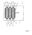
- FIG. 1 2 shows a view of an electrochemical lead-acid battery 1 with a multiplicity of alternatingly arranged lead-containing anode and cathode plates 2a, 2b, between which separators 3 are arranged.
- the anode and cathode plates 2a, 2b with the separators 3 are received in a vessel 4 which is filled with electrolyte.
- the separators 3 each consist of a microporous separator layer 5 made of polyethylene, which is enclosed on both sides by a fiber layer 6a, 6b.
- the fiber layers 6a, 6b are ultrasonically welded at the edge regions with an ultrasonic seam 7a, 7b with the associated separator layer 5. This is made possible by the selection of polyethylene as Separator harshmaterial and polyester, in particular polyolefin for the fiber layers 6a, 6b in the form of a non-woven fabric optionally with glass content.
- the fiber layers 6a, 6b can also be connected to the separator layer 5 thermally, by sewing or otherwise.
- the separator layers 5 made of polyethylene may optionally also contain silica.
- the fiber length is more than 1 mm and the fiber thickness of the fiber layers 6a, 6b is more than 1 ⁇ m, so that the electrolyte is not kept capillary.
- the resulting different adhesions of the electrolyte in the fiber and separator layers 6, 5 are advantageous.
- the absorbency of the fiber layers 6a, 6b is reduced by the relatively large chamfer length and the relatively large fiber thicknesses.
- the base thicknesses of the two fiber layers 6a, 6b and the separator layer 5 in the range of 100 microns to 600 microns for the fiber layers and 100 microns to 400 microns for the Separator harshen the total thickness of the separator can be adjusted. It is essential that between two adjacent anode and cathode plates 2a, 2b, only a three-layered separator 3 is arranged.
Landscapes
- Chemical & Material Sciences (AREA)
- Chemical Kinetics & Catalysis (AREA)
- Electrochemistry (AREA)
- General Chemical & Material Sciences (AREA)
- Cell Separators (AREA)
- Secondary Cells (AREA)
Description
- Die Erfindung betrifft einen elektrochemischen Bleiakkumulator mit einer Vielzahl alternierend angeordneter bleihaltiger Anoden- und Kathodenplatten, mit Separatoren jeweils zwischen benachbarten Anoden- und Kathodenplatten, und mit die Anoden-und Kathodenplatten sowie die Separatoren umgebendes Elektrolyt, wobei die Separatoren jeweils eine mikroporöse Separatorschicht aus Polyethylen und auf jeder Oberfläche der Separatorschicht eine Faserschicht aus Polyestervlies hat und die mikroporösen Separatorschichten und die Faserschichten eine Dicke von mindestens 100 µm haben.
- In dem
US-Patent 5,962,161 ist ein elektrochemischer Bleiakkumulator mit porösen Separatoren zwischen den Elektrodenplatten beschrieben. Die Separatoren sind aus extrem feinem Fasermaterial mit einem Durchmesser von weniger als 5 µm gebildet. Die faserhaltige Separatorschicht ist mit einem Lösungsmittel behandelt, um von Säure durchtränkt werden zu können und die flüssige Säure komplett zu absorbieren. - Weiterhin ist aus der
US 1,056,273 ein elektrochemischer Bleiakkumulator mit Separatoren zwischen den Elektrodenplatten beschrieben, die eine zwischen zwei Vliesschichten aus säureresistentem thermoplastischem Harz angeordnete Schicht aus Kieselgur haben. Die Vliesschichten können an den Rändern miteinander verbunden werden und Taschen bilden, in die die Kieselgur-Schicht aufgenommen ist. Die mikroporöse Kieselgur-Schicht ist mit etwa 500 µm relativ dick und führt zusammen mit der Vliesschicht zu einer relativ starken Immobilisierung des Elektrolyten aufgrund einer kapillaren Saugfähigkeit. - Weiterhin ist in dem
US-Patent 6,689,509 B2 ein elektrochemischer Bleiakkumulator mit einer Faserschicht beschrieben, die von zwei mikroporösen Polyethylen-Membranen eingeschlossen und mit diesen beispielsweise durch Kleben,Ultraschallschweißen oder Vernähen verbunden ist. - In der
DE 19 49 958 C3 ist ein Separator für wartungsfreie Akkumulatoren offenbart, bei dem ultrafeine Fasermatten mit einem Faserdurchmesser von weniger als 1 µm eingesetzt sind. Die verwendeten Schichten haben eine Porosität von 70 bis 95 %. Für größere Schichtdicken wird vorgeschlagen, dass mikroporöses Material und ultrafeine Fasermatten derart abwechselnd aufeinander zu folgen, dass die äußeren, an den Elektroden anliegenden Schichten stets aus ultrafeinen Fasermatten bestehen. - Aus der
EP 0 811 479 B1 ist ein Separator mit einer mikroporösen Polyolefin-Membran und einer Vliesschicht auf mindestens einer Oberfläche der mikroporösen Membran für eine Lithium-lonen-Wickelbatterie beschrieben. Die Membran hat eine Dicke von 25 bis 200 µm und die Vliesschichten eine Dicke von 30 bis 500 µm. Die Fasern der Vliesschicht haben einen Durchmesser von 0,1 bis 500 µm. - In der
WO 98/12759 A1 - Gegenüber der nassen Blei-Säure-Batterien hat die Immobilisierung von Elektrolyt, insbesondere in AGM-Batterien, folgende Nachteile:
- schlechtes Preis- Leistungsverhältnis;
- längere Formationsdauer / schlechtere Formierbarkeit;
- schlechte Massenausnutzung, geringere Leistungsfähigkeit;
- zusätzlich teure Komponenten, z. B. Glasvlies und Ventilstopfen;
- teures Material für den Batteriekasten, z. B. auf Grund der höheren mechanischen Festigkeit und Talkum gefülltes Polypropylen PP;
- dickwandige, schwere Batteriekästen;
- erhöhter Montageaufwand (gleichzeitiger Satzpressdruck);
- spezielle positive und negative Massen;
- spezielle Befülleinrichtungen für die Schwefelsäure;
- erhöhter Prüfaufwand
-
EP 0121 771 A1 offenbart einen Separator für Bleiakkumulatoren, bei dem ein Glasfaservlies mindestens auf einer Seite über seine gesamte Fläche mit einer mikroporösen Kunststoffschicht aus einem Polyolefin fest verbunden ist. Bei diesem zwischen porösen Schichten liegenden Vlies wird der Innenwiderstand stark angehoben und ein Protonen- und Sulfationenaustausch wird behindert. Zudem wird die aktive Masse nicht hinreichend durch die mikroporösen Kunststoffschichten gehalten. -
US 5,376,477 A offenbart einen Bleiakkumulator mit Separatoren, die aus drei Schichten gebildet sind. Eine mikroporöse Separatorschicht wird zwischen zwei Faserschichten gelegt, um einen Separatorverbund zu schaffen, der um die Elektroden gewickelt wird. - Das Problem der bekannten Separatoren besteht darin, dass durch die feinen und / oder dicken Vliesschichten der Elektrolyt relativ stark festgelegt ist, da die Säure kapillar gehalten wird.
- Aufgabe der vorliegenden Erfindung ist es daher, einen verbesserten elektrochemischen Bleiakkumulator zu schaffen, bei dem die Adhäsion des Elektrolyten in den
- Separatoren zwischen den Elektrodenplatten verringert ist. Der Bleiakkumulator sollte zudem preisgünstig herstellbar sein.
- Die Aufgabe wird durch einen elektrochemischen Bleiakkumulator mit den Merkmalen des Anspruchs 1 gelöst.
- Die Faserschichten sind aus Polyestervlies und an Randbereichen fest mit der zugeordneten Separatorschicht verbunden, indem die Faserschichten an den Randbereichen mit einer Ultraschallschweißnaht mit der zugeordneten Separatorschicht ultraschallverschweißt ist.
- Im Unterschied zu den herkömmlichen Separatoren mit eine mikroporöse Separatorschicht abdeckenden Faserschichten wird vorgeschlagen, dass die Faserschichten eine relativ große Faserlänge und relativ großen Faserdurchmesser haben und die mikroporöse Separatorschicht relativ dick ist. Durch die an sich bekannte Verwendung einer mikroporösen Separatorschicht aus Polyethylen können die Faserschichten an den Randbereichen fest mit der zugeordneten Separatorschicht durch Ultraschallverschweißen verbunden werden.
- Durch die relativ große Faserlänge und den relativ großen Faserdurchmesser wird erreicht, dass der Elektrolyt nicht kapillar gehalten wird und in den drei Schichten, nämlich den Faserschichten und der Separatorschicht unterschiedliche Adhäsionen des Elektrolyten auftreten. Hierzu wird die Saugfähigkeit der Faserschichten durch die Wahl der relativ großen Faserlänge und Faserdurchmessers erhöht.
- Dabei wurde erkannt, dass sich dreischichtige Separatoren, bei denen ein Vlies zwischen zwei mikroporöse Schichten eingebaut ist, für Starterbatterien nicht verwenden lassen. Vielmehr sollte die Masse durch die aussenliegenden Vliese gehalten werden. Diese Funktionalität wird durch poröse Schichten nicht aufgebracht. Zudem wurde bei zwischen porösen Schichten liegendem Vlies der Innenwiderstand stark angehoben werden und ein Protonen- und Sulfationenaustausch nicht möglich sein. Damit käme die Stromentnahme aus der Batterie zum Erliegen.
- Die Separatorschichten können auch auf mindestens einer Oberfläche eine Vielzahl von Rippen haben, so dass der dreischichtige Separator immer noch eine ausreichend ebene Fläche bildet, die an den Elektrodenplatten flächendeckend anliegen kann.
- Die Faserschichten beispielsweise ein Polyolefinfaservlies sein. In Verbindung mit der mikroporösen Polyethylen-Separatorschicht können die Faserschichten dann an den Randbereichen mit der Separatorschicht ultraschallverschweißt werden. Hierdurch ist eine preiswerte und dauerhafte Verbindung der Faserschicht mit der Separatorschicht gewährleistet.
- Die Faserschichten haben vorzugsweise eine Dicke von bis zu 600 µm und die Separatorschichten eine Dicke von bis zum 400 µm. Die Separatoren sind damit mit etwa 300 µm bis 1600 µm relativ dick.
- Die Porosität der Separatorschichten liegt vorzugsweise in einer Größenordnung von 50 bis 70 %.
- Die Erfindung wird nachfolgend anhand der beigefügten Zeichnung näher erläutert. Es zeigt:
-
Figur 1 - Draufsicht auf einen Ausschnitt eines elektrochemischen Bleiakkumulators mit alternierend angeordneten Anoden- und Kathodenplatten und zwischen liegenden Separatoren. - Die
Figur 1 lässt einen Aussicht eines elektrochemischen Bleiakkumulators 1 mit einer Vielzahl alternierend angeordneter bleihaltiger Anoden- und Kathodenplatten 2a, 2b erkennen, zwischen denen Separatoren 3 angeordnet sind. Die Anoden- und Kathodenplatten 2a, 2b mit den Separatoren 3 sind in einem Gefäß 4 aufgenommen, das mit Elektrolyt gefüllt ist. - Die Separatoren 3 bestehen jeweils aus einer mikroporösen Separatorschicht 5 aus Polyethylen, die auf beiden Seiten durch eine Faserschicht 6a, 6b eingeschlossen ist. Die Faserschichten 6a, 6b sind an den Randbereichen mit einer Ultraschallnaht 7a, 7b mit der zugeordneten Separatorschicht 5 ultraschallverschweißt. Dies wird durch die Auswahl von Polyethylen als Separatorschichtmaterial und Polyester, insbesondere Polyolefin für die Faserschichten 6a, 6b in Form eines Faservlieses ggf. mit Glasanteil möglich.
- Die Faserschichten 6a, 6b können aber auch thermisch, durch Vernähen oder auf sonstige Weise mit der Separatorschicht 5 verbunden werden.
- Die Separatorschichten 5 aus Polyethylen können ggf. auch Kieselsäure enthalten.
- Wesentlich ist, dass die Faserlänge mehr als 1 mm und die Faserdicke der Faserschichten 6a, 6b mehr als 1 µm beträgt, so dass der Elektrolyt nicht kapillar gehalten wird. Die hierbei auftretenden unterschiedlichen Adhäsionen des Elektrolyten in den Faser- und Separatorschichten 6, 5 sind vorteilhaft. Zudem wird durch die relativ große Fasenlänge und die relativ großen Faserdicken die Saugfähigkeit der Faserschichten 6a, 6b reduziert.
- Durch Variation der Grunddicken der beiden Faserschichten 6a, 6b und der Separatorschicht 5 im Bereich von 100 µm bis 600 µm für die Faserschichten und 100 µm bis 400 µm für die Separatorschichten kann die Gesamtdicke des Separators eingestellt werden. Wesentlich dabei ist, dass zwischen zwei benachbarten Anoden-und Kathodenplatten 2a, 2b lediglich ein drei-schichtiger Separator 3 angeordnet ist.
- Durch eine Vielzahl von Rippen auf der Oberfläche der Separatorschichten 5 kann eine gewisse Säurebewegung zwischen den Anoden- und Kathodenplatten 2a, 2b ermöglicht werden.
Claims (6)
- Elektrochemischer Bleiakkumulator (1) mit einer Vielzahl alternierend angeordneter bleihaltiger Anoden- und Kathodenplatten (2a, 2b), mit Separatoren (3) jeweils zwischen benachbarten Anoden- und Kathodenplatten (2a, 2b), und mit die Anoden- und Kathodenplatten (2a, 2b) sowie die Separatoren (3) umgebendes Elektrolyt, wobei die Separatoren jeweils eine mikroporöse Separatorschicht (5) aus Polyethylen und auf jeder Oberfläche der Separatorschicht (5) eine Faserschicht (6a, 6b) und die mikroporösen Separatorschichten (5) und die Faserschichten (6a, 6b) eine Dicke von jeweils mindestens 100 µm haben, und wobei die durchschnittliche Faserlänge der Faserschichten mehr als 1 mm und der durchschnittliche Faserdurchmesser der Faserschichten (6a, 6b) mehr als 1 µm beträgt, dadurch gekennzeichnet, dass die Faserschichten (6a, 6b) aus Polyestervlies gebildet und an Randbereichen fest mit der zugeordneten Separatorschicht (5) verbunden sind, indem die Faserschichten (6a, 6b) an den Randbereichen mit einer Ultraschallschweißnaht (7a, 7b) mit der zugeordneten Separatorschicht (5) ultraschallverschweißt sind.
- Elektrochemischer Bleiakkumulator (1) nach Anspruch 1, dadurch gekennzeichnet, dass die Separatorschichten (5) auf mindestens einer Oberfläche eine Vielzahl von Rippen haben.
- Elektrochemischer Bleiakkumulator (1) nach einem der vorhergehenden Ansprüche, dadurch gekennzeichnet, dass die Faserschichten (6a, 6b) als als Polyolefinfaservlies, ausgebildet sind.
- Elektrochemischer Bleiakkumulator (1) nach einem der vorhergehenden Ansprüche, dadurch gekennzeichnet, dass die Faserschichten (6a, 6b) eine Dicke von bis zu 600 µm haben.
- Elektrochemischer Bleiakkumulator (1) nach einem der vorhergehenden Ansprüche, dadurch gekennzeichnet, dass die Separatorschichten (5) eine Dicke von bis zu 400 µm haben.
- Elektrochemischer Bleiakkumulator (1) nach einem der vorhergehenden Ansprüche, dadurch gekennzeichnet, dass die Porosität der Separatorschichten (5).50 bis 70 % beträgt.
Applications Claiming Priority (1)
| Application Number | Priority Date | Filing Date | Title |
|---|---|---|---|
| DE102004045095A DE102004045095B3 (de) | 2004-09-17 | 2004-09-17 | Elektrochemischer Bleiakkumulator |
Publications (2)
| Publication Number | Publication Date |
|---|---|
| EP1638157A1 EP1638157A1 (de) | 2006-03-22 |
| EP1638157B1 true EP1638157B1 (de) | 2009-08-12 |
Family
ID=35220170
Family Applications (1)
| Application Number | Title | Priority Date | Filing Date |
|---|---|---|---|
| EP05017813A Expired - Lifetime EP1638157B1 (de) | 2004-09-17 | 2005-08-17 | Separator für Elektrochemischen Bleiakkumulator |
Country Status (5)
| Country | Link |
|---|---|
| US (1) | US20070259260A1 (de) |
| EP (1) | EP1638157B1 (de) |
| AT (1) | ATE439686T1 (de) |
| DE (2) | DE102004045095B3 (de) |
| ES (1) | ES2327533T3 (de) |
Families Citing this family (7)
| Publication number | Priority date | Publication date | Assignee | Title |
|---|---|---|---|---|
| FR2886767B1 (fr) * | 2005-06-02 | 2007-07-27 | Accumulateurs Fixes | Accumulateur alcalin ouvert comportant une membrane microporeuse. |
| US20100304210A1 (en) * | 2005-12-16 | 2010-12-02 | Yi-Ming Lin | Lead acid battery having lightly gelled electrolyte |
| US20110305932A1 (en) * | 2006-01-25 | 2011-12-15 | Tulsee Satish Doshi | Heat transfer layered electrodes |
| FI121611B (fi) * | 2007-02-06 | 2011-01-31 | Enfucell Oy | Ohutparisto ja menetelmä ohutpariston valmistamiseksi |
| ITMI20121345A1 (it) * | 2012-07-31 | 2014-02-01 | Io F I A M M Spa In Forma Abbreviata Fiamm Spa | Batteria al piombo acido ad elevata efficienza al ciclaggio stop&start |
| US9685646B2 (en) * | 2013-10-03 | 2017-06-20 | Johns Manville | Pasting paper made of glass fiber nonwoven comprising carbon graphite |
| KR102680879B1 (ko) * | 2015-10-07 | 2024-07-04 | 다라믹 엘엘씨 | 개선된 성능을 갖는 침수형 납축전지, 개선된 전지 분리막, 및 이와 관련된 방법들 |
Family Cites Families (11)
| Publication number | Priority date | Publication date | Assignee | Title |
|---|---|---|---|---|
| FR585609A (fr) * | 1924-09-29 | 1925-03-04 | Loye Et Touzot | Séparateur perfectionné pour accumulateurs électriques |
| US3914501A (en) * | 1969-06-27 | 1975-10-21 | Union Carbide Corp | Porous products and processes therefor |
| DE1949958C3 (de) * | 1969-10-03 | 1980-09-25 | Robert Bosch Gmbh, 7000 Stuttgart | Separator für wartungsfreie Akkumulatoren |
| DE8307549U1 (de) * | 1983-03-16 | 1984-08-23 | Grace Gmbh, 2000 Norderstedt | Separator fuer bleiakkumulatoren |
| US4855196A (en) * | 1988-06-23 | 1989-08-08 | Kw Battery Company | Multilaminate material and separator assembly for electrochemical cells |
| US5376477A (en) * | 1992-11-10 | 1994-12-27 | Teledyne Industries, Inc. | Storage battery and plate separator systems for a storage battery |
| US5922492A (en) * | 1996-06-04 | 1999-07-13 | Tonen Chemical Corporation | Microporous polyolefin battery separator |
| AU4593697A (en) * | 1996-09-20 | 1998-04-14 | Johns Manville International, Inc. | Resilient mat; a method of making the resilient mat and a battery including the resilient mat |
| US5962161A (en) * | 1997-01-14 | 1999-10-05 | Daramic, Inc. | Recombinant battery separator |
| US6766817B2 (en) * | 2001-07-25 | 2004-07-27 | Tubarc Technologies, Llc | Fluid conduction utilizing a reversible unsaturated siphon with tubarc porosity action |
| US6689509B2 (en) * | 2001-09-20 | 2004-02-10 | Daramic, Inc. | Laminated multilayer separator for lead-acid batteries |
-
2004
- 2004-09-17 DE DE102004045095A patent/DE102004045095B3/de not_active Expired - Fee Related
-
2005
- 2005-08-17 AT AT05017813T patent/ATE439686T1/de not_active IP Right Cessation
- 2005-08-17 ES ES05017813T patent/ES2327533T3/es not_active Expired - Lifetime
- 2005-08-17 EP EP05017813A patent/EP1638157B1/de not_active Expired - Lifetime
- 2005-08-17 DE DE502005007881T patent/DE502005007881D1/de not_active Expired - Lifetime
- 2005-09-16 US US11/229,334 patent/US20070259260A1/en not_active Abandoned
Also Published As
| Publication number | Publication date |
|---|---|
| DE102004045095B3 (de) | 2005-11-24 |
| US20070259260A1 (en) | 2007-11-08 |
| ATE439686T1 (de) | 2009-08-15 |
| EP1638157A1 (de) | 2006-03-22 |
| DE502005007881D1 (de) | 2009-09-24 |
| ES2327533T3 (es) | 2009-10-30 |
Similar Documents
| Publication | Publication Date | Title |
|---|---|---|
| DE60209781T2 (de) | Multischicht-verbundseparator für bleiakkumulatoren | |
| CN101919088B (zh) | 电池隔膜结构 | |
| DE10327080B4 (de) | Separatormaterial zum Bilden eines Separators für einen Säureakkumulator und Verfahren zu deren Herstellung | |
| DE10336380B4 (de) | Ultradünner, poröser und mechanisch stabiler Vliesstoff und dessen Verwendung | |
| EP1852926B1 (de) | Separator zur Anordnung in Batterien und Batterie | |
| EP2693529B1 (de) | Fasermatte für Batterieplattenverstärkung | |
| JP2025094181A (ja) | 繊維マットを含む改良されたセパレータ、これを使用する鉛蓄電池、ならびにこれと関連する方法およびシステム | |
| DE19924137C2 (de) | Elektrodeneinheit für wiederaufladbare elektrochemische Zellen | |
| CN101501892A (zh) | 能源设备用隔板及包含其的能源设备 | |
| EP1638157B1 (de) | Separator für Elektrochemischen Bleiakkumulator | |
| KR100415797B1 (ko) | 알칼리전지용격리판및그의제조방법 | |
| EP2368285B1 (de) | Textiles flächiges material für eine batterieelektrode | |
| DE102020131055A1 (de) | Drucksteuerungsventilstruktur und Spannungsspeichermodul | |
| DE102006018411B4 (de) | Elektrischer Doppelschichtkondensator | |
| DE202004020668U1 (de) | Elektrochemischer Bleiakkumulator | |
| DE69934043T2 (de) | Batterie mit eingekapselten Elektrodenplatten | |
| US6537696B2 (en) | Nonwoven separator for a nickel-metal hydride battery | |
| WO2023143879A1 (de) | Energiespeicherzelle | |
| JPS61281454A (ja) | 電池用セパレ−タ | |
| DE4019092C2 (de) | ||
| JP2002124242A (ja) | 電池用セパレータとその製造方法およびこれを組み込んだ電池 | |
| CN112259918A (zh) | 一种复合式隔板及电池 | |
| DE102025121860A1 (de) | Separator für eine batterie mit einem nicht-wässrigen elektrolyten und batterie mit einem nicht-wässrigen elektrolyten | |
| JPH03230473A (ja) | 電池用セパレータ及びその製造方法 | |
| DE102006054308A1 (de) | Elektrodenanordnung für eine Batterie oder Sekundärbatterie |
Legal Events
| Date | Code | Title | Description |
|---|---|---|---|
| PUAI | Public reference made under article 153(3) epc to a published international application that has entered the european phase |
Free format text: ORIGINAL CODE: 0009012 |
|
| AK | Designated contracting states |
Kind code of ref document: A1 Designated state(s): AT BE BG CH CY CZ DE DK EE ES FI FR GB GR HU IE IS IT LI LT LU LV MC NL PL PT RO SE SI SK TR |
|
| AX | Request for extension of the european patent |
Extension state: AL BA HR MK YU |
|
| 17P | Request for examination filed |
Effective date: 20060718 |
|
| AKX | Designation fees paid |
Designated state(s): AT BE BG CH CY CZ DE DK EE ES FI FR GB GR HU IE IS IT LI LT LU LV MC NL PL PT RO SE SI SK TR |
|
| 17Q | First examination report despatched |
Effective date: 20061201 |
|
| GRAP | Despatch of communication of intention to grant a patent |
Free format text: ORIGINAL CODE: EPIDOSNIGR1 |
|
| GRAS | Grant fee paid |
Free format text: ORIGINAL CODE: EPIDOSNIGR3 |
|
| GRAA | (expected) grant |
Free format text: ORIGINAL CODE: 0009210 |
|
| AK | Designated contracting states |
Kind code of ref document: B1 Designated state(s): AT BE BG CH CY CZ DE DK EE ES FI FR GB GR HU IE IS IT LI LT LU LV MC NL PL PT RO SE SI SK TR |
|
| REG | Reference to a national code |
Ref country code: GB Ref legal event code: FG4D Free format text: NOT ENGLISH |
|
| REG | Reference to a national code |
Ref country code: CH Ref legal event code: EP |
|
| REG | Reference to a national code |
Ref country code: IE Ref legal event code: FG4D |
|
| REF | Corresponds to: |
Ref document number: 502005007881 Country of ref document: DE Date of ref document: 20090924 Kind code of ref document: P |
|
| REG | Reference to a national code |
Ref country code: ES Ref legal event code: FG2A Ref document number: 2327533 Country of ref document: ES Kind code of ref document: T3 |
|
| LTIE | Lt: invalidation of european patent or patent extension |
Effective date: 20090812 |
|
| PG25 | Lapsed in a contracting state [announced via postgrant information from national office to epo] |
Ref country code: LT Free format text: LAPSE BECAUSE OF FAILURE TO SUBMIT A TRANSLATION OF THE DESCRIPTION OR TO PAY THE FEE WITHIN THE PRESCRIBED TIME-LIMIT Effective date: 20090812 Ref country code: IS Free format text: LAPSE BECAUSE OF FAILURE TO SUBMIT A TRANSLATION OF THE DESCRIPTION OR TO PAY THE FEE WITHIN THE PRESCRIBED TIME-LIMIT Effective date: 20091212 Ref country code: SE Free format text: LAPSE BECAUSE OF FAILURE TO SUBMIT A TRANSLATION OF THE DESCRIPTION OR TO PAY THE FEE WITHIN THE PRESCRIBED TIME-LIMIT Effective date: 20090812 Ref country code: FI Free format text: LAPSE BECAUSE OF FAILURE TO SUBMIT A TRANSLATION OF THE DESCRIPTION OR TO PAY THE FEE WITHIN THE PRESCRIBED TIME-LIMIT Effective date: 20090812 |
|
| NLV1 | Nl: lapsed or annulled due to failure to fulfill the requirements of art. 29p and 29m of the patents act | ||
| PG25 | Lapsed in a contracting state [announced via postgrant information from national office to epo] |
Ref country code: SI Free format text: LAPSE BECAUSE OF FAILURE TO SUBMIT A TRANSLATION OF THE DESCRIPTION OR TO PAY THE FEE WITHIN THE PRESCRIBED TIME-LIMIT Effective date: 20090812 Ref country code: PL Free format text: LAPSE BECAUSE OF FAILURE TO SUBMIT A TRANSLATION OF THE DESCRIPTION OR TO PAY THE FEE WITHIN THE PRESCRIBED TIME-LIMIT Effective date: 20090812 Ref country code: NL Free format text: LAPSE BECAUSE OF FAILURE TO SUBMIT A TRANSLATION OF THE DESCRIPTION OR TO PAY THE FEE WITHIN THE PRESCRIBED TIME-LIMIT Effective date: 20090812 Ref country code: LV Free format text: LAPSE BECAUSE OF FAILURE TO SUBMIT A TRANSLATION OF THE DESCRIPTION OR TO PAY THE FEE WITHIN THE PRESCRIBED TIME-LIMIT Effective date: 20090812 |
|
| BERE | Be: lapsed |
Owner name: VB AUTOBATTERIE G.M.B.H. & CO. KGAA Effective date: 20090831 |
|
| REG | Reference to a national code |
Ref country code: IE Ref legal event code: FD4D |
|
| PG25 | Lapsed in a contracting state [announced via postgrant information from national office to epo] |
Ref country code: MC Free format text: LAPSE BECAUSE OF NON-PAYMENT OF DUE FEES Effective date: 20090831 Ref country code: PT Free format text: LAPSE BECAUSE OF FAILURE TO SUBMIT A TRANSLATION OF THE DESCRIPTION OR TO PAY THE FEE WITHIN THE PRESCRIBED TIME-LIMIT Effective date: 20091212 Ref country code: BG Free format text: LAPSE BECAUSE OF FAILURE TO SUBMIT A TRANSLATION OF THE DESCRIPTION OR TO PAY THE FEE WITHIN THE PRESCRIBED TIME-LIMIT Effective date: 20091112 |
|
| REG | Reference to a national code |
Ref country code: CH Ref legal event code: PL |
|
| PG25 | Lapsed in a contracting state [announced via postgrant information from national office to epo] |
Ref country code: CH Free format text: LAPSE BECAUSE OF NON-PAYMENT OF DUE FEES Effective date: 20090831 Ref country code: RO Free format text: LAPSE BECAUSE OF FAILURE TO SUBMIT A TRANSLATION OF THE DESCRIPTION OR TO PAY THE FEE WITHIN THE PRESCRIBED TIME-LIMIT Effective date: 20090812 Ref country code: IE Free format text: LAPSE BECAUSE OF FAILURE TO SUBMIT A TRANSLATION OF THE DESCRIPTION OR TO PAY THE FEE WITHIN THE PRESCRIBED TIME-LIMIT Effective date: 20090812 Ref country code: LI Free format text: LAPSE BECAUSE OF NON-PAYMENT OF DUE FEES Effective date: 20090831 Ref country code: EE Free format text: LAPSE BECAUSE OF FAILURE TO SUBMIT A TRANSLATION OF THE DESCRIPTION OR TO PAY THE FEE WITHIN THE PRESCRIBED TIME-LIMIT Effective date: 20090812 Ref country code: DK Free format text: LAPSE BECAUSE OF FAILURE TO SUBMIT A TRANSLATION OF THE DESCRIPTION OR TO PAY THE FEE WITHIN THE PRESCRIBED TIME-LIMIT Effective date: 20090812 Ref country code: CZ Free format text: LAPSE BECAUSE OF FAILURE TO SUBMIT A TRANSLATION OF THE DESCRIPTION OR TO PAY THE FEE WITHIN THE PRESCRIBED TIME-LIMIT Effective date: 20090812 |
|
| PG25 | Lapsed in a contracting state [announced via postgrant information from national office to epo] |
Ref country code: SK Free format text: LAPSE BECAUSE OF FAILURE TO SUBMIT A TRANSLATION OF THE DESCRIPTION OR TO PAY THE FEE WITHIN THE PRESCRIBED TIME-LIMIT Effective date: 20090812 |
|
| PLBE | No opposition filed within time limit |
Free format text: ORIGINAL CODE: 0009261 |
|
| STAA | Information on the status of an ep patent application or granted ep patent |
Free format text: STATUS: NO OPPOSITION FILED WITHIN TIME LIMIT |
|
| PG25 | Lapsed in a contracting state [announced via postgrant information from national office to epo] |
Ref country code: BE Free format text: LAPSE BECAUSE OF NON-PAYMENT OF DUE FEES Effective date: 20090831 |
|
| 26N | No opposition filed |
Effective date: 20100517 |
|
| PG25 | Lapsed in a contracting state [announced via postgrant information from national office to epo] |
Ref country code: GR Free format text: LAPSE BECAUSE OF FAILURE TO SUBMIT A TRANSLATION OF THE DESCRIPTION OR TO PAY THE FEE WITHIN THE PRESCRIBED TIME-LIMIT Effective date: 20091113 |
|
| PG25 | Lapsed in a contracting state [announced via postgrant information from national office to epo] |
Ref country code: AT Free format text: LAPSE BECAUSE OF NON-PAYMENT OF DUE FEES Effective date: 20090817 |
|
| PG25 | Lapsed in a contracting state [announced via postgrant information from national office to epo] |
Ref country code: LU Free format text: LAPSE BECAUSE OF NON-PAYMENT OF DUE FEES Effective date: 20090817 |
|
| PG25 | Lapsed in a contracting state [announced via postgrant information from national office to epo] |
Ref country code: HU Free format text: LAPSE BECAUSE OF FAILURE TO SUBMIT A TRANSLATION OF THE DESCRIPTION OR TO PAY THE FEE WITHIN THE PRESCRIBED TIME-LIMIT Effective date: 20100213 |
|
| PG25 | Lapsed in a contracting state [announced via postgrant information from national office to epo] |
Ref country code: TR Free format text: LAPSE BECAUSE OF FAILURE TO SUBMIT A TRANSLATION OF THE DESCRIPTION OR TO PAY THE FEE WITHIN THE PRESCRIBED TIME-LIMIT Effective date: 20090812 |
|
| PG25 | Lapsed in a contracting state [announced via postgrant information from national office to epo] |
Ref country code: CY Free format text: LAPSE BECAUSE OF FAILURE TO SUBMIT A TRANSLATION OF THE DESCRIPTION OR TO PAY THE FEE WITHIN THE PRESCRIBED TIME-LIMIT Effective date: 20090812 |
|
| REG | Reference to a national code |
Ref country code: DE Ref legal event code: R082 Ref document number: 502005007881 Country of ref document: DE Representative=s name: MEISSNER, BOLTE & PARTNER GBR, DE Ref country code: DE Ref legal event code: R082 Ref document number: 502005007881 Country of ref document: DE Representative=s name: MEISSNER BOLTE PATENTANWAELTE RECHTSANWAELTE P, DE |
|
| REG | Reference to a national code |
Ref country code: FR Ref legal event code: PLFP Year of fee payment: 12 |
|
| REG | Reference to a national code |
Ref country code: FR Ref legal event code: PLFP Year of fee payment: 13 |
|
| REG | Reference to a national code |
Ref country code: FR Ref legal event code: PLFP Year of fee payment: 14 |
|
| REG | Reference to a national code |
Ref country code: DE Ref legal event code: R082 Ref document number: 502005007881 Country of ref document: DE Representative=s name: MEISSNER BOLTE PATENTANWAELTE RECHTSANWAELTE P, DE |
|
| REG | Reference to a national code |
Ref country code: ES Ref legal event code: PC2A Owner name: CLARIOS GERMANY GMBH & CO. KGAA Effective date: 20201006 |
|
| REG | Reference to a national code |
Ref country code: DE Ref legal event code: R079 Ref document number: 502005007881 Country of ref document: DE Free format text: PREVIOUS MAIN CLASS: H01M0002160000 Ipc: H01M0050409000 |
|
| REG | Reference to a national code |
Ref country code: DE Ref legal event code: R082 Ref document number: 502005007881 Country of ref document: DE Representative=s name: MEISSNER BOLTE PATENTANWAELTE RECHTSANWAELTE P, DE Ref country code: DE Ref legal event code: R081 Ref document number: 502005007881 Country of ref document: DE Owner name: CLARIOS GERMANY GMBH & CO. KGAA, DE Free format text: FORMER OWNER: VB AUTOBATTERIE GMBH & CO. KGAA, 30419 HANNOVER, DE |
|
| PGFP | Annual fee paid to national office [announced via postgrant information from national office to epo] |
Ref country code: IT Payment date: 20230822 Year of fee payment: 19 Ref country code: GB Payment date: 20230828 Year of fee payment: 19 Ref country code: ES Payment date: 20230901 Year of fee payment: 19 |
|
| PGFP | Annual fee paid to national office [announced via postgrant information from national office to epo] |
Ref country code: FR Payment date: 20230825 Year of fee payment: 19 Ref country code: DE Payment date: 20230829 Year of fee payment: 19 |
|
| REG | Reference to a national code |
Ref country code: DE Ref legal event code: R119 Ref document number: 502005007881 Country of ref document: DE |
|
| GBPC | Gb: european patent ceased through non-payment of renewal fee |
Effective date: 20240817 |
|
| PG25 | Lapsed in a contracting state [announced via postgrant information from national office to epo] |
Ref country code: DE Free format text: LAPSE BECAUSE OF NON-PAYMENT OF DUE FEES Effective date: 20250301 |
|
| PG25 | Lapsed in a contracting state [announced via postgrant information from national office to epo] |
Ref country code: GB Free format text: LAPSE BECAUSE OF NON-PAYMENT OF DUE FEES Effective date: 20240817 |
|
| PG25 | Lapsed in a contracting state [announced via postgrant information from national office to epo] |
Ref country code: IT Free format text: LAPSE BECAUSE OF NON-PAYMENT OF DUE FEES Effective date: 20240817 |
|
| PG25 | Lapsed in a contracting state [announced via postgrant information from national office to epo] |
Ref country code: FR Free format text: LAPSE BECAUSE OF NON-PAYMENT OF DUE FEES Effective date: 20240831 |
|
| REG | Reference to a national code |
Ref country code: ES Ref legal event code: FD2A Effective date: 20251001 |
|
| PG25 | Lapsed in a contracting state [announced via postgrant information from national office to epo] |
Ref country code: ES Free format text: LAPSE BECAUSE OF NON-PAYMENT OF DUE FEES Effective date: 20240818 |