EP1640487A2 - Dispositif de décision d'une valeur de consigne - Google Patents
Dispositif de décision d'une valeur de consigne Download PDFInfo
- Publication number
- EP1640487A2 EP1640487A2 EP05020348A EP05020348A EP1640487A2 EP 1640487 A2 EP1640487 A2 EP 1640487A2 EP 05020348 A EP05020348 A EP 05020348A EP 05020348 A EP05020348 A EP 05020348A EP 1640487 A2 EP1640487 A2 EP 1640487A2
- Authority
- EP
- European Patent Office
- Prior art keywords
- information
- cloth
- loom
- requirement
- set points
- Prior art date
- Legal status (The legal status is an assumption and is not a legal conclusion. Google has not performed a legal analysis and makes no representation as to the accuracy of the status listed.)
- Withdrawn
Links
Images



Classifications
-
- D—TEXTILES; PAPER
- D03—WEAVING
- D03J—AUXILIARY WEAVING APPARATUS; WEAVERS' TOOLS; SHUTTLES
- D03J1/00—Auxiliary apparatus combined with or associated with looms
- D03J1/005—Displays or displaying data
-
- D—TEXTILES; PAPER
- D03—WEAVING
- D03D—WOVEN FABRICS; METHODS OF WEAVING; LOOMS
- D03D51/00—Driving, starting, or stopping arrangements; Automatic stop motions
-
- D—TEXTILES; PAPER
- D03—WEAVING
- D03D—WOVEN FABRICS; METHODS OF WEAVING; LOOMS
- D03D51/00—Driving, starting, or stopping arrangements; Automatic stop motions
- D03D51/002—Avoiding starting marks
-
- D—TEXTILES; PAPER
- D03—WEAVING
- D03D—WOVEN FABRICS; METHODS OF WEAVING; LOOMS
- D03D51/00—Driving, starting, or stopping arrangements; Automatic stop motions
- D03D51/12—Driving, starting, or stopping arrangements; Automatic stop motions for adjusting speed
Definitions
- the present invention relates to a technique for deciding a set point of an operating condition of a loom, based on input information.
- Patent Documents (1: Japanese Patent Appln. Public Disclosure No. 61-239057 Official Gazette, 2: Japanese Patent Appln. Public Disclosure No. 63-42943 Official Gazette, 3: Japanese Patent Appln. Public Disclosure No. 1-314759 Official Gazette) describe an indicator provided in a loom.
- the indicator of each document is connected to a host computer used in common by a plurality of looms.
- the host computer can output a set condition of a loom in correspondence to each of plural weaving conditions such as kind of yarn, weaving width, weaving density, warp texture and the like.
- an operator When changing cloths to be woven, an operator firstly inputs cloth conditions into an indicator provided on a loom. Next, the host computer extracts a set point on the basis of the inputted conditions and sends it to a setting device of the loom. The operator performs setting operation of the loom according to the set point indicated in the indicator and carries out trial weaving.
- the set point sent from the host computer and indicated in the indictor takes into account neither circumstances such as the quality of prepared warp and weft yarns, the number of weavers, which are different in each weaving factory, nor required items to be weighted by each weaving factory (such as, for example, the productivity of cloth is regarded more important than the quality thereof or vice versa).
- Patent Document 3 An art to change set points during continuous operation of a loom is also known (Patent Document 3). This art deems, for example, the number of times of stoppage during continuous operation as cloth quality data and changes the set rotational frequency of a loom according to the number of stoppage.
- An object of the present invention is to provide a set point of a loom which takes into account requirement information weighted by a weaving factory.
- the set point deciding apparatus comprises an input device for inputting input information, and an output device for deciding and outputting a set point of operating conditions of a loom on the basis of the input information.
- the input information includes specification information of a cloth and requirement information on production of the cloth.
- the output device includes a database in which a plurality of set points of the operating conditions of the loom are previously stored in correspondence to the specification information of the cloth and the requirement information on production, and search means for searching the set points of the corresponding operating conditions of the loom from the database.
- the output device searches set points of the corresponding operating conditions from the database on the basis of the inputted specification information of the cloth and the requirement information on production, and decides and outputs the searched set points as set points of the operating conditions of the loom.
- the set point deciding apparatus searches set points of operating conditions conforming to the conditions from the database on the basis of the specification information of cloth and requirement information on production of cloth required by a weaving factory as a user and decides and outputs them as set points of operating conditions on production of the cloth.
- the operator therefore, sets a loom according to the outputted information, so that he can immediately start producing the cloth under the conditions desired by the weaving factory.
- the input information further includes the specification information of the loom.
- the input information is pre-stored in the database in correspondence to the specification information of cloth, the requirement information on production and the specification information of the loom.
- the output device may search the set points of corresponding operating conditions from the database on the basis of the inputted specification information of cloth, the requirement information and the specification information of the loom, and decide and output the searched set points as the set points of the operating conditions of the loom.
- the specifications of the looms disposed in a weaving factory are not always the same but are considered to differ in operating conditions of the looms corresponding to the requirement information.
- the set point deciding apparatus searches, on the basis of the specification information of the loom to be further inputted, set points of the operating conditions from the database to which the specification information of the loom is added, adds the specification information of the loom and outputs the set points of operating conditions suitable for the specification of the loom, and the operator sets the set points of operating conditions of each loom, thereby enabling to immediately start the production of the cloth under the conditions desired by the weaving factory.
- the requirement information may include at least one requirement selecting information from among the requirement for quality of the cloth, production requirement for the cloth and energy efficiency requirement in production of the cloth.
- the requirement information may include information on degree of weighting in at least one of the requirement among the requirement for quality of the cloth, the productivity requirement for the cloth and the energy efficiency requirement in production of the cloth.
- the requirement desired by the weaving factory can be subdivided and designated in correspondence to the degree of weighting, thereby enabling to enhance the precision of the conditions desired by the weaving factory.
- the loom includes at least one of a back roller, an easing device, a dropper box, a warp shedding device and a temple which are warp guide members, and the set points may include either information on a mounting position of the warp guide member or information on its driving mode.
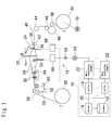
- the set point deciding apparatus 10 comprises a setter 14 which is provided in each of plural looms 12 in one-to-one correspondence, a server 16 and a database 18.
- the server 16 reads out predetermined set points from the database 18 according to a requirement signal from the setter 14 and/or writes the predetermined set points into the database 18.
- the server 16 and the plural setters 14 provided in each loom 12 are connected through a network 20.
- Each setter 14 is connected to the main controller 22 of each loom 12. Accordingly, the set point deciding apparatus 10 is connected to the main controllers 22 through the setters 14 which are provided in each loom 12 in one-to-one correspondence.
- Each of the setters 14 constituting a part of the set point deciding apparatus 10 incorporates a touch panel serving as an input device and indicator, a communication port for connecting the main controller 22 of the loom with the server 16 so as to send and receive information, a central processing unit for controlling them, and a memory for storing a control program for inputting by the touch panel through the CPU and dealing with communication through the communication port.
- the input device into which so-called input information in the specification corresponds to the touch panel.
- the output device for deciding and outputting the set points of the operating conditions of the loom on the basis of the input information corresponds to the constitution including the server 16 serving as search means, the database 18 and the setters 14 as a whole.
- the warp yarns 24 is linked from a let-off beam 26 around which the warp yarns 24 is wound like a sheet to a cloth fell 36 through a back roller 28, a plurality of dropper pins 30, a plurality of heald frames 32 and a reed 34.
- the weft yarns 38 inserted into a warp shedding are beaten by the reed 34 against the cloth fell 36 to be a cloth 40.
- the cloth 40 reaches a take-up roll 46 from the cloth fell 36 through a temple 42 and a guide roller 44.
- the cloth 40, reaching the take-up roll 46, is let off to a cloth beam 50 by the take-up roll 46 and a pair of press rollers 48.
- the let-off cloth 40 is taken up by the cloth beam 50.
- An easing device 52 for driving the back roller 28, a plurality of heald frames 32 and the reed 34 are driven upon receipt of rotation force of a main shaft 56 which is rotated by an output shaft of a main shaft motor 54.
- the back roller 28 is swung by the easing device 52.
- An arm 58 pivoting the back roller 28 at its one end so as to rotate freely is swingably borne at its other end relative to the frame of the loom 12.
- the back roller 28 is in a state of being movable forward or backward by swinging of the arm 58 in the forward and backward direction.
- a rod 62 is connected to nearly the central portion of the arm 58.
- One end of the rod 62 is connected to the front end of the crank 60 to be rotated by rotation of the main shaft 56, and the other end of the rod 62 is connected to nearly the central portion of the arm 58. Therefore, the rotation of the main shaft 56 is converted into reciprocation therethrough and transmitted to the arm 58, thereby swinging the back roller 28.
- Such an easing device 52 is provided to restrain variation in warp tension accompanying the warp shedding motion.
- the position (in the rightward and leftward direction in Fig. 1) and the height (in the vertical direction in Fig. 1) of the back roller 28 are made adjustable through a member (not shown). By changing them, the quality of the cloth 40 can be changed.
- Each warp yarn 24 is passed through a hole provided in each dropper pin 30.
- the dropper pin 30 is brought into electrical contact with a dropper box 64.
- the dropper box 64 detects breaking of the warp yarn 24.
- the dropper pins 30 are arranged between the back roller 28 and the heald frame 32. Consequently, since the dropper pins 30 are positioned such that their box frame contacts the warp yarns in a state of under shed, if the height and position of the dropper box 64 in the forward and backward direction change, the shape of the shedding of the warp yarns 24 changes to cause a difference in warp tension, thus affecting the quality of the cloth 40. Therefore, the quality of the cloth 40 can be changed by changing the height and position of the dropper box 64.
- Each heald frame 32 is vertically reciprocated by a warp shedding device 66 to open the warp yarns 24 upward and downward.
- the warp shedding device 66 receives rotating motion of the main shaft 56 to be rotated by the main shaft motor 54, converts it to reciprocal motion and transmits to each heald frame 32 by a mechanism (not shown).
- the warp shedding device 66 can adjust a cross timing which is a main shaft angle for the heald frame 32 to close the center shed, a shedding amount which is a range for the heald frame 32 to move upward and downward, and the height of the heald frame 32 with a frame end face of the loom as a reference position. Consequently, by changing these, the quality of the cloth 40 can be changed.
- a pair of temples 42 on the right and left sides in the weaving width direction stretch both ends of the cloth 40 outward of the cloth 40.
- the height and position of each temple 42 in the forward and backward of the weaving direction are made adjustable. Therefore, by changing them, the quality of the cloth 40 can be changed.
- the reed 34 is driven to swing by a beating drive portion 68 which receives the rotation of the main shaft 56 and beats the weft yarns 38 inserted into the shedding of the warp yarns 24 against the cloth fell 36.
- the beating drive portion 68 can adjust the beating timing and force.
- the take-up roll 46 is rotated through a gear mechanism (not shown) constituted by a gear-like decelerator for receiving the rotation of a take-up motor 70.
- the rotated take-up roll 46 lets off the cloth 40 to the cloth beam 50 in cooperation with the pair of press rollers 48.
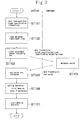
- FIG. 2 a setting process using the set point deciding apparatus 10 of this case is explained.
- An embodiment shown in the following is one wherein an operator of a weaving factory inputs in a touch panel as an input device of the setter 14 which of "the quality of the cloth” and “the productivity of the cloth” is to be preceded as a desired item and wherein the set point deciding apparatus 10 makes the corresponding operating condition of the loom indicated in a touch panel as an indicator of the setter 14 of the loom.
- the setting to weight "the quality of the cloth” means a setting to improve a feeling of the cloth and make reed mark (distance of reed wire) appearing in the cloth 40 unnoticeable. To realize this, it suffices to set a running route of the warp yarns 24 so as to generate a difference in tension between the opening upper and lower warp yarns 24.
- the heights and positions of members associated with the warp running route are set so as to generate a difference in tension between the opening upper and lower warp yarns 24.
- a stress (damage) to the warp yarns 24 becomes greater, the number of stoppage tends to be increased, and the productivity (operation rate) of the cloth 40 is somewhat lowered.
- the quality of the cloth is more weighted, such setting becomes more useful for a weaving factory.
- the weight "the productivity of the cloth” is a setting by which yarn breakage hardly occurs, namely, a setting contrary to the setting to weight "the quality of the cloth.” To realize this, it suffices to set a running route of the warp yarns 24 so that a difference in tension between the opening upper and lower warp yarns 24 may become small (or remain the same).
- Table 1 shows key points for setting in correspondence to the desired information in each device associated with the warp route in the loom.
- Table 1 Example of Setting for Device Associated with Warp Line loom device object of setting detailed setting mode when weighting quality when weighting operation back roller height position make higher standard forward and backward position move to forward position standard easing device (positive type) cross timing retard standard easing amount increase standard easing device (negative type) spring force weaken standard dropper height position make higher standard forward and backward position move to forward position standard shedding device cross timing retard standard shedding amount enlarge standard frame height make higher standard temple height position make higher standard
- Fig. 2 shows, as an example, a process of setting for deciding the set point of a device associated with the warp running route shown in Table 1.
- An example of the indication on a touch panel screen 72 of the setter at this time is shown in Figs. 3 - 7.
- the illustration shows a state that an operator firstly touches the "reed drawing-in width" in area A and makes the ten keys indicated to input the numerals for the "reed drawing-in width.”
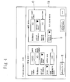
- Fig. 4 shows a state that "190" was inputted as the value of the "reed drawing-in width” in Fig. 3. Also, in area A on the left side showing the information on the warp yarns 24 are shown a state that the "total number” and the “thickness” are respectively inputted as “10000" yarns and yarn number count “40” as the information on the warp yarns 24 and a state that the "unit of thickness” and the "kind” are selectively inputted as “cotton count” and "cotton yarn” respectively.
- buttons E As shown in Fig. 4, after inputting the information on the cloth 40 by using the touch panel of the setter 14, an operator presses button E for "advance to 2/2" to display the screen 72 shown in Fig. 5.
- the operator after inputting the input information necessary for deciding set points of the operating conditions of the loom including the specification information of the cloth 40 and the requirement information on production of the cloth 40, presses the button H for "indication of adjustment amount" as indicated in the touch panel of the setter 14 (ST103).
- the setter 14 when the button H for "indication of adjustment amount" as indicated in the touch panel is pressed, outputs (transmits) the cloth specification, the loom specification and items that the weaving factory weights as the input information to the server 16 via a communication port.
- the server 16 searches from the database 18 a set point by which the inputted input information coincides with an item of the database 18 (ST104). Further, the server 16 outputs (transmits) the resulted set point to the setter 14.
- the server 16 may temporarily select a plurality of set points close to the input information and output a value computed by interpolation operation from the temporarily selected set points as the set point to the setter 14.
- the server 16 may also compute a set point by a function by making the input information an argument and output the computed set point to the setter 14.
- the database 18 stores data shown, for example, in the following table.
- the database 18 extractably stores the set points relating to the operating conditions of the loom, specification information of the loom, specification information of the cloth, and requirement information desired by the weaving factory. So, as for the database 18 to be stored, examples in which set points for position and height for mounting the back roller 28 and set points for the drive amount of the easing device 52 for driving the back roller are stored respectively in correspondence to the degrees in five grades of weighting the quality of the cloth are shown in Tables 2 and 3.
- these pieces of the input information may reflect others than mentioned above or may be based on other input information.
- the number of the grades of the weighting degree may be other than five (excluding "1").
- the operator selects which of the "quality of the cloth” and the “productivity of cloth” is to be weighted. Accordingly, the output device outputs a set point of a suitable operating condition.
- the data shown in Table 2 is systematically constituted as to the set point for the position of the back roller 28.
- the position/height of the back roller as shown in the Table concretely means the mounting position/height of a receiving member which receives the back roller, and more concretely, shows the marking No. information marked in correspondence to the fixed position fixed of a frame (not shown)/height from the frame reference position (not shown).
- the data shown in Table 3 is systematically constituted as to the set point for setting the position of the easing device 52.
- the easing amount of the easing device shown in the Table means, more concretely, positional information of connecting point to the crank 60 of the rod 52.
- the data shown in Tables 2 and 3 respectively weight the cloth quality as one the weighting items.
- the input information to be used for extraction of set points may reflect others or may be based on other input information than these when extracting set points of the operating conditions other than the warp running route. Also, the number of the grades of the weighting degrees can be other than three mentioned above (excluding "1").
- the data shown in Table 4 is systematically constituted as to the set point for setting the position of the back roller 28.
- the data shown in Table 5 is systematically constituted as to the set point for setting the position of the easing device 52. All the data in Tables 4 and 5 make the quality of cloth, productivity of cloth 40 and energy-saving property weighted items which can be selected by the weaving factory as requirement information.
- the setter 14 Upon receipt of the set point of the operating condition searched on the basis of the database 18 and sent from the server 20, the setter 14 switches to the screen 72 to indicate the set point for recommended operating condition, and immediately makes the screen 72 of the touch panel indicate the set point sent from the server 20 (ST105).
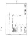
- the setter 14 indicates the set points sent from the server 20 in the screen 72 of the touch panel, as shown in Fig. 6, as the set points of the recommended operating conditions of the back roller 28, easing device 52, warp shedding device 66, dropper box 64 and temple 42.
- the setter 14 indicates the inputted set points in the screen 72 of the touch panel, as shown in Fig. 7, as set points of recommended operating conditions the shedding amount of each heald frame 32 of the warp shedding device 66 and the height of the frame.
- the operator based on the set points indicated in the screen 72 of the setter 14, carries out mechanical setting of the back roller 28, easing device 52, warp shedding device 66, dropper box 64, temple 42 and warp shedding device 66 on the basis of the set points indicated in the screen 72 of the setter 14, and thereafter, performs trial weaving (ST106).
- the operator confirms the state of the cloth 40 woven on trial, and if necessary, presses the button for "return to input” again to display the screens 72 shown in Figs. 4 and 5, thereby re-inputting the input information.
- the foregoing set point deciding apparatus 10 can be adapted as follows.
- the apparatus of the loom 12 to be set was explained as an apparatus relating to the warp line as the warp running route, it is not restricted to this but is also applicable to other devices which require other mechanical setting operations which can set the set points by an electrical signal, for example, it is possible to output each set point in a weft inserting device or a loom rotation frequency controller, that is, weft inserting conditions (jet timing, pressure) or a set rotation frequency and the like.
- the set point deciding apparatus 10 may set in a device (i.e., the corresponding controller) of the loom 12.
- the weighting items may include other items than the quality of the cloth and the productivity of the cloth. For example, as for the energy efficiency shown in Tables 3 and 4, the amount of power consumption, the amount of fluid consumption and the like in case of a fluid jet loom are taken into account, but it may further include an item associated with the weaving cost as a new requirement item.
- the set points of the operating conditions of the loom 12 which is the information stored in the database 18 may be adapted to be renewable by a user's input operation or by the renewal data to be supplied by a textile machine manufacturer.
- the set point deciding apparatus 10 includes the server 16 and the data base 18 used in common with the foregoing plural looms 12, such a set point deciding function may be included in the setter 14 of each loom 12.
- the output device of the set point deciding apparatus 10 is explained to be an indicator (a touch panel) for displaying in a screen as means to substantially output the detected set points, but the outputting means is not restricted to the indicator but, instead thereof, a printer provided in a loom control office may be adapted to print and output detected set points.
- set points are decided and outputted for a back roller, an easing device, a dropper box, a warp shedding device and a temple, respectively, on the basis of a plurality of requirement information to be inputted, but it is also possible to constitute such that set points are decided and outputted for one of devices having the highest degree of influence.
Landscapes
- Engineering & Computer Science (AREA)
- Textile Engineering (AREA)
- Looms (AREA)
Applications Claiming Priority (1)
| Application Number | Priority Date | Filing Date | Title |
|---|---|---|---|
| JP2004278959A JP2006089885A (ja) | 2004-09-27 | 2004-09-27 | 設定値決定装置 |
Publications (2)
| Publication Number | Publication Date |
|---|---|
| EP1640487A2 true EP1640487A2 (fr) | 2006-03-29 |
| EP1640487A3 EP1640487A3 (fr) | 2010-04-21 |
Family
ID=35453575
Family Applications (1)
| Application Number | Title | Priority Date | Filing Date |
|---|---|---|---|
| EP05020348A Withdrawn EP1640487A3 (fr) | 2004-09-27 | 2005-09-19 | Dispositif de décision d'une valeur de consigne |
Country Status (4)
| Country | Link |
|---|---|
| EP (1) | EP1640487A3 (fr) |
| JP (1) | JP2006089885A (fr) |
| KR (1) | KR20060051073A (fr) |
| CN (1) | CN1754998B (fr) |
Families Citing this family (6)
| Publication number | Priority date | Publication date | Assignee | Title |
|---|---|---|---|---|
| CN102286836B (zh) * | 2010-06-17 | 2015-05-20 | 株式会社丰田自动织机 | 用于分析织机中的编织条件的方法 |
| JP5860656B2 (ja) * | 2011-10-11 | 2016-02-16 | 津田駒工業株式会社 | 織機における情報表示装置 |
| JP5991159B2 (ja) * | 2012-11-16 | 2016-09-14 | 株式会社豊田自動織機 | エアジェット織機におけるサブノズルの配列選択装置 |
| CN106802749A (zh) * | 2015-11-25 | 2017-06-06 | 阿里巴巴集团控股有限公司 | 数值输入方法及装置 |
| WO2018101066A1 (fr) * | 2016-12-02 | 2018-06-07 | 村田機械株式会社 | Machine de bobinage de fil |
| CN106884256B (zh) * | 2017-04-20 | 2019-03-26 | 广东溢达纺织有限公司 | 织机系统及纬密自动计数方法 |
Family Cites Families (10)
| Publication number | Priority date | Publication date | Assignee | Title |
|---|---|---|---|---|
| JPS59125941A (ja) * | 1982-12-27 | 1984-07-20 | 津田駒工業株式会社 | 流体噴射式織機の流体噴射パターン制御方法 |
| JPS61239057A (ja) * | 1985-04-09 | 1986-10-24 | 津田駒工業株式会社 | 織機の集中制御方法およびその装置 |
| KR910008045B1 (ko) * | 1988-03-17 | 1991-10-07 | 쯔다고마 고오교오 가부시끼가이샤 | 직기의 최적 제어방법 |
| JP2592641B2 (ja) * | 1988-03-17 | 1997-03-19 | 津田駒工業株式会社 | 織機の最適制御方法 |
| JP2592645B2 (ja) * | 1988-03-28 | 1997-03-19 | 津田駒工業株式会社 | 織機の集中制御方法 |
| US5276627A (en) * | 1989-06-21 | 1994-01-04 | Kabushiki Kaisha Toyoda Jidoshokki Seisakusho | Method of setting weaving conditions for a jet loom |
| DE10127099A1 (de) * | 2001-06-02 | 2002-12-19 | Dornier Gmbh Lindauer | Verfahren zum Einstellen von Webmaschinen und Webmaschinenanlagen |
| JP2003096645A (ja) * | 2001-09-26 | 2003-04-03 | Tsudakoma Corp | 織機のユーザ支援システム用のホストコンピュータと、それを使用するユーザ支援システム |
| CN1492301A (zh) * | 2002-10-21 | 2004-04-28 | 津田驹工业株式会社 | 织机机台信息输入输出系统 |
| JP2004225172A (ja) * | 2003-01-20 | 2004-08-12 | Tsudakoma Corp | 織段防止機能付き織機 |
-
2004
- 2004-09-27 JP JP2004278959A patent/JP2006089885A/ja active Pending
-
2005
- 2005-09-07 KR KR1020050083146A patent/KR20060051073A/ko not_active Withdrawn
- 2005-09-19 EP EP05020348A patent/EP1640487A3/fr not_active Withdrawn
- 2005-09-26 CN CN2005101050780A patent/CN1754998B/zh not_active Expired - Fee Related
Also Published As
| Publication number | Publication date |
|---|---|
| KR20060051073A (ko) | 2006-05-19 |
| JP2006089885A (ja) | 2006-04-06 |
| EP1640487A3 (fr) | 2010-04-21 |
| CN1754998A (zh) | 2006-04-05 |
| CN1754998B (zh) | 2010-12-29 |
Similar Documents
| Publication | Publication Date | Title |
|---|---|---|
| EP1396562B1 (fr) | Procédé et dispositif d'affichage des défauts de tissage dans les métiers à tisser | |
| CN1262701C (zh) | 调节织机织造参数的方法和控制装置 | |
| CN1754998B (zh) | 设定值确定装置 | |
| US20070295423A1 (en) | Power Loom, Particularly an Air Jet Power Loom, for the Production of a Leno Fabric with Integral Patterning | |
| JP4646191B2 (ja) | 繊維機械の支援方法 | |
| EP1637636B1 (fr) | Dispositif de décision d'une valeur de consigne | |
| JPH05239742A (ja) | 織機による織布の製造方法およびその装置 | |
| CN206521565U (zh) | 一种小样织布机 | |
| CN111139568B (zh) | 一种多功能小型全自动织样机 | |
| EP0350980B1 (fr) | Dispositif pour régler la tension de la chaîne dans les métiers à tisser | |
| CN1327062C (zh) | 具有横档防止功能的织机 | |
| CN214361950U (zh) | 一种分条整经机的断经自停装置 | |
| JP5189737B2 (ja) | 織機の開口装置、及びその開口装置を使用した織機における織付け方法 | |
| JP5137302B2 (ja) | 織機の運転装置 | |
| CN102899783B (zh) | 织机的织造方法和织造装置 | |
| CN101663426B (zh) | 用于控制驱动电机的方法和用于织机的驱动电机的控制器 | |
| JPH0319934A (ja) | 電子ドビー織機における柄パターン入力設定方法及び柄パターン異常表示方法 | |
| CN213266902U (zh) | 一种用于生产混纺织品的剑杆织机布边纱架 | |
| JPH05272037A (ja) | 織機における機台条件設定装置 | |
| JP4718213B2 (ja) | 織機の経糸張力制御方法及び装置 | |
| JP4126403B2 (ja) | 複合ドビー機 | |
| JP2827012B2 (ja) | 織機回転数の最適制御方法 | |
| JPH08158205A (ja) | 手機における筬打ち方法 | |
| US853519A (en) | Warp stop mechanism. | |
| JPH07100901B2 (ja) | 織機における経糸制御方法 |
Legal Events
| Date | Code | Title | Description |
|---|---|---|---|
| PUAI | Public reference made under article 153(3) epc to a published international application that has entered the european phase |
Free format text: ORIGINAL CODE: 0009012 |
|
| AK | Designated contracting states |
Kind code of ref document: A2 Designated state(s): AT BE BG CH CY CZ DE DK EE ES FI FR GB GR HU IE IS IT LI LT LU LV MC NL PL PT RO SE SI SK TR |
|
| AX | Request for extension of the european patent |
Extension state: AL BA HR MK YU |
|
| PUAL | Search report despatched |
Free format text: ORIGINAL CODE: 0009013 |
|
| AK | Designated contracting states |
Kind code of ref document: A3 Designated state(s): AT BE BG CH CY CZ DE DK EE ES FI FR GB GR HU IE IS IT LI LT LU LV MC NL PL PT RO SE SI SK TR |
|
| AX | Request for extension of the european patent |
Extension state: AL BA HR MK YU |
|
| 17P | Request for examination filed |
Effective date: 20101021 |
|
| AKX | Designation fees paid |
Designated state(s): BE CH DE IT LI |
|
| 17Q | First examination report despatched |
Effective date: 20110506 |
|
| STAA | Information on the status of an ep patent application or granted ep patent |
Free format text: STATUS: THE APPLICATION IS DEEMED TO BE WITHDRAWN |
|
| 18D | Application deemed to be withdrawn |
Effective date: 20110917 |