EP1640926A2 - Bracelet de poignet ou de cheville et procédé de surveillance de la personne à l'aide d'un bracelet de poignet ou de cheville - Google Patents
Bracelet de poignet ou de cheville et procédé de surveillance de la personne à l'aide d'un bracelet de poignet ou de cheville Download PDFInfo
- Publication number
- EP1640926A2 EP1640926A2 EP05020628A EP05020628A EP1640926A2 EP 1640926 A2 EP1640926 A2 EP 1640926A2 EP 05020628 A EP05020628 A EP 05020628A EP 05020628 A EP05020628 A EP 05020628A EP 1640926 A2 EP1640926 A2 EP 1640926A2
- Authority
- EP
- European Patent Office
- Prior art keywords
- band
- alarm
- element according
- integrated
- transmitter
- Prior art date
- Legal status (The legal status is an assumption and is not a legal conclusion. Google has not performed a legal analysis and makes no representation as to the accuracy of the status listed.)
- Withdrawn
Links
Images

Classifications
-
- G—PHYSICS
- G08—SIGNALLING
- G08B—SIGNALLING SYSTEMS, e.g. PERSONAL CALLING SYSTEMS; ORDER TELEGRAPHS; ALARM SYSTEMS
- G08B21/00—Alarms responsive to a single specified undesired or abnormal condition and not otherwise provided for
- G08B21/18—Status alarms
- G08B21/22—Status alarms responsive to presence or absence of persons
-
- G—PHYSICS
- G07—CHECKING-DEVICES
- G07C—TIME OR ATTENDANCE REGISTERS; REGISTERING OR INDICATING THE WORKING OF MACHINES; GENERATING RANDOM NUMBERS; VOTING OR LOTTERY APPARATUS; ARRANGEMENTS, SYSTEMS OR APPARATUS FOR CHECKING NOT PROVIDED FOR ELSEWHERE
- G07C9/00—Individual registration on entry or exit
- G07C9/20—Individual registration on entry or exit involving the use of a pass
- G07C9/28—Individual registration on entry or exit involving the use of a pass the pass enabling tracking or indicating presence
-
- G—PHYSICS
- G07—CHECKING-DEVICES
- G07C—TIME OR ATTENDANCE REGISTERS; REGISTERING OR INDICATING THE WORKING OF MACHINES; GENERATING RANDOM NUMBERS; VOTING OR LOTTERY APPARATUS; ARRANGEMENTS, SYSTEMS OR APPARATUS FOR CHECKING NOT PROVIDED FOR ELSEWHERE
- G07C11/00—Arrangements, systems or apparatus for checking, e.g. the occurrence of a condition, not provided for elsewhere
- G07C2011/02—Arrangements, systems or apparatus for checking, e.g. the occurrence of a condition, not provided for elsewhere related to amusement parks
Definitions
- the invention relates to a bracelet or foot band of a band-shaped element whose ends are connected to each other so that the circumference of the band is smaller than the smallest possible circumference of the hand or the foot of the wearer of the band. Furthermore, the invention relates to a method for monitoring the residence times of a person in a closed area, in particular for monitoring compliance with the permitted residence times of a teenager in a closed area, which is subject to a restriction by the Teen Protection Act, wherein such an arm or foot band is used , as well as the use of such an arm or foot band.
- DE 199 54 408 A1 discloses a method for controlling the entry or exit of an area by persons, who in each case carry a signal transmitter which transmits or triggers a code related to the respective person. Thereby the receipt of a certain code is called Warning signal for an unauthorized entry or exit of the area detected by the respective person.
- a method for monitoring a person in which the person is equipped with a receiving device for a position determination signal and a transmitting device, wherein a location information is determined from the position determination signal and transmitted by the transmitting device to a receiving station.
- DE 101 24 093 B1 also discloses a system for locating a person who has a stationary base station for transmitting and receiving radio signals which is connected to a communication network via which a message is sent to other persons or bodies in the event of a triggered alarm is mailable. Furthermore, the system has a first mobile transceiver device communicating with the base station and carried by the person, at which an alarm can be triggered manually or automatically upon the occurrence of an event. Finally, the system has a second mobile transmitter-receiver device carried by the person, which can be controlled by the first mobile transmitter-receiver device when the alarm is triggered and transmits a distress signal which can be received and localized by a location-receiver device.
- the invention is therefore based on the object , an arm or foot band of the type mentioned above and a method for monitoring the residence of a person in a closed area, in particular for monitoring compliance with the permitted residence times of a teenager in a closed area, a restriction by The Teen Protection Act is subject to make available or suggest by means of such an arm or ankle strap, so that it is possible in simple and even at large events manageable way to comply with the supervision provisions.
- the tape and the method should be feasible or operable in a cost-effective manner, so that a comprehensive and effective monitoring of the persons concerned can take place.
- the solution of this problem by the invention is characterized in that in the arm or foot band alarm means are integrated, which can trigger an alarm when exposed to a non-influenced by the wearer of the tape signal.
- the application of the signal triggering the alarm signal is carried out by an integrated clock in the band.
- the application of the alarm signal triggering signal is carried out by a built-in band in the receiver, which may be in communication with a station arranged stationary.
- an alarm is triggered at a given time, which indicates that the permitted, latest time until which the wearer of the band is allowed to remain in a closed area , has expired or is about to expire.
- This is of particular importance and is particularly useful for monitoring the allowable residence of an adolescent in a closed area, with access to the area subject to a restriction under the Teen Protection Act, as is the case, for example, for discotheques or public events.
- the alarm means can be designed for the staggered delivery of at least two alarms. It is preferably provided that the time-staggered alarms are different, in particular with regard to their nature, strength and / or duration.
- the alarm means may be designed to deliver an optical alarm, i. H. for example as a lamp, flash lamp or LED. Alternatively or additionally, it may be provided that the alarm means are suitable for emitting an acoustic alarm; In this case, for example, a piezo element for generating a warning sound or a built-in speaker in the band can be provided.
- the ends of the band may have a closure which can only be opened with special opening means.
- the closure should be able to be opened by name only authorized personnel who can remove the tape from the arm or foot of the wearer, for example, at the output of the monitored area.
- the closure is preferred as such formed known magnetic or electromagnetic closure that can only be opened with a special device.
- the tape should be as indestructible as possible, which is why it preferably consists of a tensile and tear-resistant material. It may have reinforcing fibers inside it.
- a preferred embodiment uses hard plastic as a strip material.
- the arm or foot band further comprises an RF transmitter (radio frequency transmitter), which excites an RF receiver (radio frequency receiver) with second alarm means when the band in the vicinity of the RF Recipient.
- RF transmitter radio frequency transmitter
- RF receiver radio frequency receiver
- second alarm means when the band in the vicinity of the RF Recipient.
- a direction finder is provided, which is integrated in the tape and allows locating the tape.
- the band also has an emergency button, which triggers the alarm means when actuated.
- the tape is over the emergency button communicates with an emergency transmitter via which an emergency signal can be sent to an emergency receiver.
- the alarm is triggered by signaling means in the form of a clock integrated in the band.
- the alarm is triggered by signaling means in the form of a receiver integrated in the band, which communicates with a stationary transmitter in communication connection and which causes the triggering of the alarm signal at the given time.
- the alarm means emit or cause the signaling means in a predetermined time sequence at least two alarms.
- the time-staggered alarms can be different in terms of their nature, strength and / or duration.
- a preferred embodiment of the method provides that at the given time first an optical alarm and after a predetermined waiting time an audible alarm is triggered.
- the audible alarm can in turn staggered have several partial alarms, which are getting louder.
- the proposed arm or ankle strap is preferably used to monitor compliance with the allowable residence time of an adolescent in an enclosed area subject to a restriction by the Teen Protection Act. It is especially thought of discos and public events, where the band can be used particularly advantageous.
- the proposed tape and the method in indoor swimming o. ⁇ . Used the entrance fees often result depending on a selected period of use. Then, as an alarm time, a time can be given, at which one must begin by leaving the bath so as to be able to leave the bathroom in good time, that additional charges are avoided.
- VIP areas can be monitored with the proposed band or the method according to the invention.
- the volume then constitutes an access authorization for a certain period of time.
- car racing events of all kinds, horse racing events and football events are mentioned.
- the tape can then be a special pass, z. B. a press card or a VIP card, replace.
- the band can also be used in the military field, if certain areas may be entered only at predetermined allowable times.
- the band can also replace a visitor badge. The same applies, for example, to industrial companies, both their employees and their visitors.
- the tapes can be used, for example, for the personnel who may stay in certain areas only at certain predetermined times.
- An example of an application are pilots who are allowed to stay in a VIP area by means of the tape while other people who are equipped with the tape are not allowed to do so (for example ground personnel only certain designated areas and, for example, cleaning staff in turn only other zones).
- Another interesting application of the invention is the protection of persons, whereby in particular the provided additional functions of the band can be of advantage.
- a data memory chip can be integrated into the tape on which relevant data can be stored, read, printed and edited. This can be used, for example, to store information about food and drinks consumed on an event on the chip, in which case a corresponding billing can take place by means of the stored data.
- personal data can also be stored on the memory chip, permissible or unacceptable areas of interest can then be defined in-memory, so that in the given case the alarm means are activated when an unauthorized zone is entered.
- a triggering of a door opener function for permitted zones or areas can take place.
- a particular embodiment of the invention proposal finally provides that by means of the proposed arm or foot strap security personnel, z. As in the industrial sector, it is then monitored whether all the areas to be controlled (eg doors) were checked, in which case not only the fact that this happened, but also when on the memory chip.
- all the areas to be controlled eg doors
- the proposed invention is particularly and primarily in the monitoring of persons, which - as shown - especially a monitoring of young people with respect to the permitted attendance at events or in discotheques is possible.
- the agent used according to the invention is generally referred to as an element into which the alarm means according to the invention are integrated.
- the element can be connected to the object to be monitored. This is to be understood as meaning that the element is fixed to the object to be monitored in such a way that it can be disassembled or opened non-destructively only with special tools (for example with a magnet that can release a magnetic closure). Only an authorized person should be able to remove the item from the object being monitored and "defuse" the item.
- the object to be monitored may be a vehicle of a general type, for example a bicycle.
- the object may be a piece of luggage on which the element together with alarm means is arranged.
- the object may be a container, e.g. In a harbor.
- the whereabouts of the object to be monitored is to be monitored, whereby at given times alarm is to be triggered if the object is not at a scheduled location or located in a scheduled area. This is of great importance with regard to security-relevant aspects.
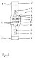
- a non-applied bracelet 1 can be seen, which consists of a band-shaped element which can be connected at its two ends 2 and 3 by means of a closure 8.
- the closure is shown only schematically. It can be designed as a magnetic or electromagnetic closure. In this case, after the application of the band 1 on the arm of a carrier, the ends 2, 3 are connected and then held by a magnetic force that it is no longer possible for the wearer to deposit the band 1. Instead, this can only be done without destruction if an authorized person (supervisor) cancels the magnetic field by means of an appropriate tool.
- any type of closure comes into consideration, for example, provided in the manner of a handcuff lock whose key is kept by an authorized person.
- the band 1 itself is made of hard plastic, so that it is not possible to cut through the band 1 without tools. The wearer of the wristband 1 is thus dependent on the wristband being removed again by an authorized person.
- the carrier 16 of the bracelet 1 has entered a discotheque 17 via an entrance 18.
- the strap 16 At the entrance 18, the strap 16, the bracelet 1 was applied in the manner explained.
- the carrier 16 When leaving the discotheque 17, the carrier 16 must return the tape 1, d. H. it is removed again at the entrance or exit 18.
- the intentional or unintentional entrainment of the tape 1 when leaving the discotheque 17 is prevented by the fact that the tape 1 - as can be seen in Fig. 1 - with an RF transmitter (radio frequency transmitter) 9 is equipped.
- this transmitter addresses RF receivers 10 'arranged at the output 18, which cause a warning signal.
- the staff at the entrance / exit 18 are pointed out that the person leaving the discotheque 17 carries a volume 1.
- the aforementioned RF transmit-receive technology is well known from the point-of-sale security store and need not be detailed here.
- the band 1 is equipped as follows. It has alarm means 4, namely a piezo noise generator 19 and a light emitting diode 20.
- the light emitting diode 20 can emit such a strong light that the carrier 16 can be warned.
- the piezo-noise generator 19 not only the carrier 16 itself, but also its surroundings pointed to the triggering of an alarm. Instead of a piezo noise generator and a conventional speaker can be used.
- a signal means 6 in the form of a radio receiver is integrated into the band 1, which can be addressed by a transmitter 7 (see Fig. 2) arranged stationarily in the discotheque 17.
- the transmitter 7 transmits a signal which is received by the signal means 6 in the band 1.
- the signaling means 6 then sends a signal to the alarm means 4, so that they respond.
- only a triggering of the light-emitting diode 20 can be initiated, so that the carrier 16 is informed of the advanced hour.
- a time interval for. B. 5 minutes to be set in motion, after the expiration of the alarm means 4 are controlled again, then z.
- an interval tone can sound over a predetermined time, so that the carrier 16 is again informed of its expiring time.
- z. B. at 24:00 clock are triggered by the signaling means 6 a continuous tone, so that the minor is forced to go to the output 18.
- the triggering of the individual alarms can also take place directly from the transmitter 7, so that the task of the signal means 6 is reduced to allow the alarm means 4 to be addressed upon receipt of a signal from the transmitter 7.
- a clock 5 is integrated, which can be used in Band 1 as a normal wristwatch.
- the clock 5 is programmed or set to a defined time, for. B. at 23:30, to which they - acting as signaling means 6 - a first time the alarm means 4 should respond. Accordingly, the clock 5 can then cause staggered further alarms, as described above, for example, at intervals of 5 minutes.
- the tape 1 is now a self-sufficient system capable of triggering the alarm at a predetermined time.
- the band 1 can be equipped with other elements to perform complementary functions.
- the already mentioned RF transmitter 9 can be used in the band 1, to prevent certain areas of the discotheque are entered by the carrier 16.
- a bar 21 is outlined, which may not be entered by underage wearers 16.
- an RF receiver 10 is arranged, which is in communication with a second alarm means 11. If the carrier 16 passes the area of the RF receiver 10, a signal is triggered via the second alarm means 11, which signals the staff in the bar 21 that an unauthorized person wants to enter the bar.
- a direction-finding transmitter 12 is also integrated in the band 1 (see Fig. 1), which makes it possible to locate the carrier 16 if necessary, which can be very advantageous in some cases. This applies, for example, in the event that the carrier 16 is no longer able to act by taking alcohol or drugs.
- the still provided emergency button 13 can prove itself. This can be related to the alarm means 4 and trigger these, in particular the piezo-noise generator 19 at its loudest stage to deter the attackers. It can also be provided that upon actuation of the emergency button 13, an emergency transmitter 14 is activated, which - for example, via radio - a stationary arranged emergency receiver 15 responds. Then, targeted help can be sent to the carrier 16, for which the direction finder 12 performs well to quickly locate the carrier 16.
- Fig. 1 Not shown in detail in Fig. 1 are common and known elements that are required for the operation of the belt 1, for example, a battery that provides the necessary power supply.
Landscapes
- Physics & Mathematics (AREA)
- General Physics & Mathematics (AREA)
- Business, Economics & Management (AREA)
- Emergency Management (AREA)
- Alarm Systems (AREA)
- Measurement Of The Respiration, Hearing Ability, Form, And Blood Characteristics Of Living Organisms (AREA)
Applications Claiming Priority (1)
| Application Number | Priority Date | Filing Date | Title |
|---|---|---|---|
| DE102004046710A DE102004046710A1 (de) | 2004-09-25 | 2004-09-25 | Arm- oder Fußband und Verfahren zum Überwachen einer Person mittels eines Arm- oder Fußbandes |
Publications (2)
| Publication Number | Publication Date |
|---|---|
| EP1640926A2 true EP1640926A2 (fr) | 2006-03-29 |
| EP1640926A3 EP1640926A3 (fr) | 2006-10-04 |
Family
ID=35447537
Family Applications (1)
| Application Number | Title | Priority Date | Filing Date |
|---|---|---|---|
| EP05020628A Withdrawn EP1640926A3 (fr) | 2004-09-25 | 2005-09-22 | Bracelet de poignet ou de cheville et procédé de surveillance de la personne à l'aide d'un bracelet de poignet ou de cheville |
Country Status (2)
| Country | Link |
|---|---|
| EP (1) | EP1640926A3 (fr) |
| DE (1) | DE102004046710A1 (fr) |
Citations (4)
| Publication number | Priority date | Publication date | Assignee | Title |
|---|---|---|---|---|
| BE903327A (fr) | 1984-09-28 | 1986-01-16 | Abel Inga | Installation pour le surveillance de personnes a l'interieur d'etablissements ouverts ou semi-ouverts, ainsi que bracelet a utiliser avec cette installation |
| DE19911211A1 (de) | 1999-03-11 | 2000-09-21 | Jochen Creutzmann | Verfahren zur Überwachung einer Person und Vorrichtung zur Durchführung des Verfahrens |
| DE19954408A1 (de) | 1999-11-12 | 2001-05-17 | Philipp Schmelter | Verfahren und Vorrichtung zum Kontrollieren des Betretens oder Verlassens eines Bereichs durch Personen oder bewegliche Sachen |
| DE10124093A1 (de) | 2001-05-16 | 2002-12-12 | Alexander Plank | System zum Lokalisieren einer Person |
Family Cites Families (7)
| Publication number | Priority date | Publication date | Assignee | Title |
|---|---|---|---|---|
| US5731757A (en) * | 1996-08-19 | 1998-03-24 | Pro Tech Monitoring, Inc. | Portable tracking apparatus for continuous position determination of criminal offenders and victims |
| US5883576A (en) * | 1998-01-14 | 1999-03-16 | De La Huerga; Carlos | Identification bracelet with electronics information |
| US6130620A (en) * | 1997-08-11 | 2000-10-10 | Electronic Monitoring Systems, Inc. | Remote monitoring system |
| DE29810098U1 (de) * | 1998-06-05 | 1999-01-28 | Beys, Lorenz, Dipl.-Ing., 40219 Düsseldorf | Telefongerät - Armbanduhr (incl. integriertem Empfänger und Vibrator) - Kombination zur stillen Alarmierung durch Vibration auf der Haut bei eingehenden Telefonanrufen mit besonderem Fokus auf eine Handy-Armbanduhr (incl. integriertem Empfänger und Vibrator)-Kombination |
| US6078260A (en) * | 1998-12-21 | 2000-06-20 | Sony Corporation | Method and apparatus for keeping track of children |
| DE19916950A1 (de) * | 1999-04-15 | 2000-10-19 | Alexandra Taube | Funk-Anlage (Vorrichtung) zum Personenschutz (insbesondere für Kinder) |
| DE10046767C1 (de) * | 2000-09-21 | 2002-04-18 | Andreas Toeteberg | Zwillingssicherung für Gebrauchsgegenstände, welche voneinander nicht getrennt werden dürfen |
-
2004
- 2004-09-25 DE DE102004046710A patent/DE102004046710A1/de not_active Ceased
-
2005
- 2005-09-22 EP EP05020628A patent/EP1640926A3/fr not_active Withdrawn
Patent Citations (4)
| Publication number | Priority date | Publication date | Assignee | Title |
|---|---|---|---|---|
| BE903327A (fr) | 1984-09-28 | 1986-01-16 | Abel Inga | Installation pour le surveillance de personnes a l'interieur d'etablissements ouverts ou semi-ouverts, ainsi que bracelet a utiliser avec cette installation |
| DE19911211A1 (de) | 1999-03-11 | 2000-09-21 | Jochen Creutzmann | Verfahren zur Überwachung einer Person und Vorrichtung zur Durchführung des Verfahrens |
| DE19954408A1 (de) | 1999-11-12 | 2001-05-17 | Philipp Schmelter | Verfahren und Vorrichtung zum Kontrollieren des Betretens oder Verlassens eines Bereichs durch Personen oder bewegliche Sachen |
| DE10124093A1 (de) | 2001-05-16 | 2002-12-12 | Alexander Plank | System zum Lokalisieren einer Person |
Also Published As
| Publication number | Publication date |
|---|---|
| EP1640926A3 (fr) | 2006-10-04 |
| DE102004046710A1 (de) | 2006-04-20 |
Similar Documents
| Publication | Publication Date | Title |
|---|---|---|
| EP0919971B1 (fr) | Système et procédé antivol pour détecter et identifier automatiquement une étiquette de surveillance d'articles | |
| DE4219678A1 (de) | Verfahren und Anordnung zur Sicherung von Personen oder Gegenständen | |
| DE4308193C2 (de) | Benutzungskontrollanlage für Lifte und Seilbahnen | |
| DE202013008368U1 (de) | Personen- und Eigentumsschutzsystem | |
| DE3232114A1 (de) | Signalanlage, insbesondere sicherungsanlage, mit kennzeichnung der durchfuehrung des testbetriebs und mit erfassung der ergebnisse der waehrend des testbetriebs durchgefuehrten pruefungen | |
| DE60002856T2 (de) | Verfahren zur verwaltung von elektronischen fahrkarten und einrichtung zu dessen durchführung | |
| EP1929451A2 (fr) | Dispositif pour controler la presence d'objets | |
| EP1532596B1 (fr) | Dispositif de recherche et de protection de personnes et procede | |
| EP1103037B1 (fr) | Procede et dispositif pour controler si des personnes ou des objets mobiles penetrent dans une zone ou quittent cette derniere | |
| DE102004046710A1 (de) | Arm- oder Fußband und Verfahren zum Überwachen einer Person mittels eines Arm- oder Fußbandes | |
| DE19512045A1 (de) | Drahtloses Diebstahlwarngerät | |
| DE19930690C2 (de) | Situationserfassungseinrichtung zur Blockadeerkennung bei Türen, Toren oder dergleichen | |
| DE2747380A1 (de) | Aktivatoreinheit fuer identifikationssysteme | |
| DE4310690C2 (de) | Einrichtung zum Sichern von Kraftfahrzeugen gegen Einbruch und Diebstahl | |
| DE3916614C2 (fr) | ||
| DE19829377C2 (de) | Mobile Notfallalarmierungsvorrichtung | |
| DE10124093B4 (de) | System zum Lokalisieren einer Person | |
| DE10315845B4 (de) | System, Systemkomponenten und Verfahren zur Abwicklung eines hermetisch validierbaren Datentransfers | |
| DE3127943A1 (de) | Geraet zum ueberwachen des abstandes zwischen zwei sich relativ zueinander bewegenden personen oder objekten | |
| EP1793352B1 (fr) | Système de surveillance et dispositif mobile d'alarme | |
| DE102005036337B4 (de) | Alarmsystem | |
| DE19954408A1 (de) | Verfahren und Vorrichtung zum Kontrollieren des Betretens oder Verlassens eines Bereichs durch Personen oder bewegliche Sachen | |
| DE4243482A1 (de) | Diebstahlsicherung | |
| DE102005036088A1 (de) | Verfahren und Vorrichtung zum Orten eines Objekts | |
| DE102018009304A1 (de) | Vorrichtung zur Alarmauslösung |
Legal Events
| Date | Code | Title | Description |
|---|---|---|---|
| PUAI | Public reference made under article 153(3) epc to a published international application that has entered the european phase |
Free format text: ORIGINAL CODE: 0009012 |
|
| AK | Designated contracting states |
Kind code of ref document: A2 Designated state(s): AT BE BG CH CY CZ DE DK EE ES FI FR GB GR HU IE IS IT LI LT LU LV MC NL PL PT RO SE SI SK TR |
|
| AX | Request for extension of the european patent |
Extension state: AL BA HR MK YU |
|
| PUAL | Search report despatched |
Free format text: ORIGINAL CODE: 0009013 |
|
| AK | Designated contracting states |
Kind code of ref document: A3 Designated state(s): AT BE BG CH CY CZ DE DK EE ES FI FR GB GR HU IE IS IT LI LT LU LV MC NL PL PT RO SE SI SK TR |
|
| AX | Request for extension of the european patent |
Extension state: AL BA HR MK YU |
|
| RAP1 | Party data changed (applicant data changed or rights of an application transferred) |
Owner name: DIGITAL CONTROL WARNING SYSTEMS GMBH & CO. KG |
|
| RIN1 | Information on inventor provided before grant (corrected) |
Inventor name: DIGITAL CONTROL WARNING SYSTEMS GMBH & CO. KG |
|
| AKX | Designation fees paid | ||
| STAA | Information on the status of an ep patent application or granted ep patent |
Free format text: STATUS: THE APPLICATION IS DEEMED TO BE WITHDRAWN |
|
| 18D | Application deemed to be withdrawn |
Effective date: 20070405 |
|
| REG | Reference to a national code |
Ref country code: DE Ref legal event code: 8566 |