EP1641394B1 - Verfahren und anordnung im zusammenhang mit der prüfung von implantaten - Google Patents
Verfahren und anordnung im zusammenhang mit der prüfung von implantaten Download PDFInfo
- Publication number
- EP1641394B1 EP1641394B1 EP04749036A EP04749036A EP1641394B1 EP 1641394 B1 EP1641394 B1 EP 1641394B1 EP 04749036 A EP04749036 A EP 04749036A EP 04749036 A EP04749036 A EP 04749036A EP 1641394 B1 EP1641394 B1 EP 1641394B1
- Authority
- EP
- European Patent Office
- Prior art keywords
- implant
- arrangement
- resonance frequency
- detected
- excitation
- Prior art date
- Legal status (The legal status is an assumption and is not a legal conclusion. Google has not performed a legal analysis and makes no representation as to the accuracy of the status listed.)
- Expired - Lifetime
Links
- 239000007943 implant Substances 0.000 title claims abstract description 65
- 238000012360 testing method Methods 0.000 title claims abstract description 28
- 238000000034 method Methods 0.000 title claims abstract description 24
- 210000000988 bone and bone Anatomy 0.000 claims abstract description 23
- 230000005291 magnetic effect Effects 0.000 claims description 20
- 230000004044 response Effects 0.000 claims description 14
- 230000005284 excitation Effects 0.000 claims description 12
- 239000003302 ferromagnetic material Substances 0.000 claims description 5
- 238000001514 detection method Methods 0.000 claims description 2
- 238000010998 test method Methods 0.000 claims description 2
- 239000000523 sample Substances 0.000 description 15
- 239000004053 dental implant Substances 0.000 description 10
- 230000010355 oscillation Effects 0.000 description 5
- 241001465754 Metazoa Species 0.000 description 3
- 239000000463 material Substances 0.000 description 3
- 206010065687 Bone loss Diseases 0.000 description 2
- RTAQQCXQSZGOHL-UHFFFAOYSA-N Titanium Chemical compound [Ti] RTAQQCXQSZGOHL-UHFFFAOYSA-N 0.000 description 2
- 230000001133 acceleration Effects 0.000 description 2
- 230000008859 change Effects 0.000 description 2
- 230000008878 coupling Effects 0.000 description 2
- 238000010168 coupling process Methods 0.000 description 2
- 238000005859 coupling reaction Methods 0.000 description 2
- 230000001066 destructive effect Effects 0.000 description 2
- 238000005259 measurement Methods 0.000 description 2
- 239000002184 metal Substances 0.000 description 2
- 229910052751 metal Inorganic materials 0.000 description 2
- 238000012986 modification Methods 0.000 description 2
- 230000004048 modification Effects 0.000 description 2
- 238000012545 processing Methods 0.000 description 2
- 239000010936 titanium Substances 0.000 description 2
- 229910052719 titanium Inorganic materials 0.000 description 2
- 208000037408 Device failure Diseases 0.000 description 1
- 241000282412 Homo Species 0.000 description 1
- NIXOWILDQLNWCW-UHFFFAOYSA-N acrylic acid group Chemical group C(C=C)(=O)O NIXOWILDQLNWCW-UHFFFAOYSA-N 0.000 description 1
- 239000004411 aluminium Substances 0.000 description 1
- 229910052782 aluminium Inorganic materials 0.000 description 1
- XAGFODPZIPBFFR-UHFFFAOYSA-N aluminium Chemical compound [Al] XAGFODPZIPBFFR-UHFFFAOYSA-N 0.000 description 1
- 230000005540 biological transmission Effects 0.000 description 1
- 229910010293 ceramic material Inorganic materials 0.000 description 1
- 238000002316 cosmetic surgery Methods 0.000 description 1
- 230000002950 deficient Effects 0.000 description 1
- 238000003745 diagnosis Methods 0.000 description 1
- 230000000694 effects Effects 0.000 description 1
- 239000003365 glass fiber Substances 0.000 description 1
- 230000035876 healing Effects 0.000 description 1
- 238000003780 insertion Methods 0.000 description 1
- 230000037431 insertion Effects 0.000 description 1
- 230000010354 integration Effects 0.000 description 1
- 239000007769 metal material Substances 0.000 description 1
- 230000003287 optical effect Effects 0.000 description 1
- 230000000737 periodic effect Effects 0.000 description 1
- 230000000704 physical effect Effects 0.000 description 1
- 230000002028 premature Effects 0.000 description 1
- 230000008569 process Effects 0.000 description 1
- 238000001228 spectrum Methods 0.000 description 1
- 230000001954 sterilising effect Effects 0.000 description 1
- 238000004659 sterilization and disinfection Methods 0.000 description 1
- 210000001519 tissue Anatomy 0.000 description 1
Images


Classifications
-
- A—HUMAN NECESSITIES
- A61—MEDICAL OR VETERINARY SCIENCE; HYGIENE
- A61B—DIAGNOSIS; SURGERY; IDENTIFICATION
- A61B5/00—Measuring for diagnostic purposes; Identification of persons
- A61B5/103—Measuring devices for testing the shape, pattern, colour, size or movement of the body or parts thereof, for diagnostic purposes
-
- A—HUMAN NECESSITIES
- A61—MEDICAL OR VETERINARY SCIENCE; HYGIENE
- A61C—DENTISTRY; APPARATUS OR METHODS FOR ORAL OR DENTAL HYGIENE
- A61C19/00—Dental auxiliary appliances
- A61C19/04—Measuring instruments specially adapted for dentistry
-
- A—HUMAN NECESSITIES
- A61—MEDICAL OR VETERINARY SCIENCE; HYGIENE
- A61B—DIAGNOSIS; SURGERY; IDENTIFICATION
- A61B5/00—Measuring for diagnostic purposes; Identification of persons
- A61B5/05—Detecting, measuring or recording for diagnosis by means of electric currents or magnetic fields; Measuring using microwaves or radio waves
-
- A—HUMAN NECESSITIES
- A61—MEDICAL OR VETERINARY SCIENCE; HYGIENE
- A61C—DENTISTRY; APPARATUS OR METHODS FOR ORAL OR DENTAL HYGIENE
- A61C8/00—Means to be fixed to the jaw-bone for consolidating natural teeth or for fixing dental prostheses thereon; Dental implants; Implanting tools
Definitions
- the present Invention relates to a method and apparatus for testing an implant attached to a bone of a human or animal subject.
- implants involves the insertion of a metal fixture Into a prepared hole in the bone. During the healing process, the surrounding bone develops an intimate contact with the implant surface and after a suitable time a prosthesis may be attached to the fixture. Such implants are frequently used in dentistry and in cosmetic surgery.
- Implant failures can be caused by errors in placement, and premature or inappropriate loading.
- a non-destructive test which could be used before loading the implant would help to reduce failures of this type, and would also enable periodic tests to be carried out on implants which are in use to ensure that they are still satisfactory.
- the test could also provide a quantitative comparison between different implant systems.
- X-rays are sometimes used to test the condition of an implant, but they can only show the presence of gross bone loss around the implant. It is also very difficult to monitor the progress of integration over time with x-rays, since it is difficult to reproduce the viewing position and angle with sufficient accuracy.
- a different sort of test albeit a crude one, is to tap the structure attached to the implant with a surgical instrument. This test can only distinguish between satisfactory implants and the most grossly defective systems.
- the international patent application no. WO 92/18053 relates to a method of testing an implant attached to a bone of a human or animal subject.
- the method comprises the steps of bringing a member into contact with the implant; detecting at least one resonance frequency of the member when it is In contact with the implant; and interpreting the detected resonance frequency in terms of the degree of attachment of the implant with respect to the bone.
- the method implies using an analysing unit being in contact with the implant through a wire.
- US 3,355,933 and WO 99/46603 relate to measuring arrangements for measuring surface vibrations of a large object.
- the arrangements presented in these documents are not suitable for small spaces, such as a mouth of a patient.
- WO 03011133 relates to a medical implant system.
- a sensor element In order to obtain information on physical states of the implant in the environment thereof, a sensor element is embedded into the implant and is connected to a measuring device which determines a physical property of the sensor element or the environment thereof and a modification thereof.
- the glass fibers of the implant are connected to a transmission element, for example a conventional transponder, and the implant itself or at a distance from the implant within the body of the patient or on the surface of the body of the patient It can also link to an optical element, which emit light and can receive such a small parabolic mirror, a lens or the like.
- a transmission element for example a conventional transponder
- the implant itself or at a distance from the implant within the body of the patient or on the surface of the body of the patient
- It can also link to an optical element, which emit light and can receive such a small parabolic mirror, a lens or the like.
- the document is silence of excitation using the detector.
- a transducer assembly is used with an apparatus for detecting the stability of a bone implant.
- the transducer assembly uses one or more transducers to excite vibrations in said bone implant and to detect a response to the vibrations.
- a coupling is used to detachably connect the one or more transducers to circuitry for driving the vibrations and detecting the response.
- a memory device is provided within the transducer assembly. The memory device can store one or more parameters read from outside of the transducer assembly via the coupling for controlling the use of the transducer.
- a vibration effectuating unit for the determination of stability of an implant in bone, a vibration effectuating unit is used, which gives a frequency signal A corresponding to the stability.
- a receiving unit receives this signal and converts it to digital information signal, which relates to the stability.
- a processing unit receives the digital signal and processes it together with information relating to distortion factors from the current situation, such as implant dimension, surface, material, anatomical site etc. The processing unit gives as output a presentation information, which disregards said factors and therefore representing only the stability.
- WO 01122880 relates to a device for measuring the mechanical impedance of its surroundings.
- the device includes a force generator, a force sensor, an accelerometer unit, an electronic unit capable of calculating the impedance of the basis of outputs received from a device component and suitable power and control signal sources.
- US 5518008 relates to a dental analyzer for analyzing dental implants includes a dental probe having a probe tip for contacting a patient's dental implant.
- An accelerometer is coupled to the probe tip.
- a hammer fired by an actuator against the accelerometer impacts the probe tip against the dental implant which vibrates the dental implant.
- the accelerometer measures the acceleration time history of the vibrating dental implant.
- a processor converts the measured acceleration time history of the dental implant into a frequency spectrum from which a diagnosis can then be made regarding the condition of the dental implant.
- US 3355933 relates to apparatus for testing mechanical properties and physical characteristics of objects from their vibrations.
- US 2002/115944 relates to a distance measurement system.
- the distance measurement system includes at least one resonant circuit, at least one magnetic element with predetermined magnetic properties, a transmitter operable to transmit an electromagnetic pulse, a receiver operable to detect oscillations emitted by said resonant circuit in response to said electromagnetic pulse, and an analyzer operable to analyze an amplitude envelope property of said oscillations, to thereby determine a distance between the resonant circuit and the magnetic element.
- the main object of the present invention is to provide contactless testing apparatus and method of an implant.
- Another object of the present invention to provide a non-destructive test, which is capable of giving a reliable indication of the quality and/or extent of the union between an implant and the bone to which it is attached in a contactless way.
- Another object of the present invention is to provide a testing arrangement, which is disposable providing a purity aspect to the invention.
- a method and arrangement for testing an implant attached to a a bone are provided.
- the method comprises the steps defined in claim 1.
- the member comprises a cantilever beam.
- the member is made of a ferromagnetic material.
- the resonance frequency is detected by means of the member disturbing a magnetic field.
- the implant includes a threaded bore, and the cantilever beam is screwed to or into the implant.
- the method further comprises the step of comparing the detected resonance frequency with one or more values for the resonance frequencies of the same or similar members in contact with other implants.
- the detected resonance frequency is compared with one or more values, taken at different times, for the resonance frequencies of the same or similar member in contact with the same implant.
- the method further includes the steps of exciting the member with a force, detecting the response of the member to the force and deriving an output, which is the ratio of the voltage of the response signal to that of the excitation signal.
- the invention also relates to an arrangement for testing an implant attached to a bone.
- the arrangement is defined in claim 15.
- the detectable part comprises a magnetic member.
- the detector comprises a coil.
- the arrangement further comprises an amplifier, a processor, and a data store.
- the signals detected by the detector are amplified by the amplifier and applied as an input to be analysed.
- the analysed output which represents a ratio of a response voltage to the excitation, is fed to the processor, which varies the frequency output of the oscillator of the analyser, and stores the results in the data store.
- the detectable part consists of a ferromagnetic material.
- the detector comprises a coil for detecting disturbances in an external magnetic field.
- the member comprises a cantilever beam.
- the beam is arranged or adapted to resonate at a frequency within the range of about 1 to 20 kHz, preferably about 1 to 10 kHz, and more preferably of the order of about 8 kHz.
- the member is disposable.
- the invention also relates to a disposable implant testing part provided for testing an implant attached to a bone.
- the disposable implant testing part comprises a detectable part, which can be detected contactless by means of a detector.
- the apparatus 100 comprises two parts, a member 110 in the form of a cantilever beam attached by means of a threaded section 111 to an implanted fixture 120.
- the implant fixture can be a dental implant attached by a threaded section 112 in a section of a bone 130, typically a human jawbone or any other type of an implant for humans or animals.
- the implant 120 may be any one of a number of known types, formed from a metal, such as titanium, from a ceramic material, or any other appropriate material. It may, for example, be of the type supplied by Nobel Biocare in the U.K.
- the member 110 is provided with a magnetic member 140.
- the magnetic member 140 can be provided at one end of the beam 110, e.g. the free end or integrated inside the beam.
- the second part of the apparatus comprises the testing apparatus 150, including a probe 151 and a response analyzer unit 152.
- the probe 150 comprises a coil 153 for detecting oscillations of the magnetic member.
- Signals detected by the probe 151 are amplified by an amplifier 154 and applied as an input to the analyser.
- the output from the analyser which represents the ratio of the response voltage to the excitation, is fed to a processor such as a microprocessor 155, which is used to vary the frequency output of the oscillator of the analyser, and store the results in a data store 156.
- the results can be printed out, and/or displayed on a display or the like.
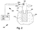
- the first part of the arrangement 200 comprises, a member 210 in the form of a cantilever beam as in the earlier embodiment attached by means of a threaded section 211 to the implanted fixture 220.
- the implant fixture can be a dental implant attached by a threaded section 212 in a section of a bone 230.
- the member 210 in this case is provided with markings 240, such as lines, arranged at one end of the beam 210.
- the second part of the arrangement comprises the testing apparatus 250, including a probe 251 and a response analyzer unit 252.
- the probe 250 comprises a light source 253a, preferably but not exclusively a laser, and a light detector 253b for detecting reflections from the beam and thus oscillations of the beam.
- the light source is preferably Laser diode.
- the beam is provided with one or several markers, such as darker (or lighter) sections, which effect the reflection of the light.
- the beam is excited manually or e.g. by means of an electrical exciter, by applying the force F on the beam.
- the light source on the tip of the probe illuminates the beam and the light detector 253b detects the reflected light.
- the detected light signal is converted to an electrical signal by the detector, and signals detected by the probe 251 are amplified by an amplifier 254 and applied as an input to the analyser.
- the output from the analyser which represents the ratio of the response voltage to the excitation, is fed to a processor such as a microprocessor 255, which is used to vary the frequency output of the oscillator of the analyser, and store the results in a data store 256.
- the results can be printed out, and/or displayed on a display or the like.
- the beam 110 is secured, i.e. screwed, to the implanted implant 120 with a predetermined torque, for example using a torque controller and counter tool.
- a torque controller and counter tool for example a torque controller and counter tool.
- the variations in resonance frequency with torque have been found to be relatively small over a practical range of torques, for example of the order of 5 to 10 Ncm, so that such torque variations should not present a problem.
- the beam is disposable, which means that it can be screwed off and disposed, providing a hygienic testing arrangement.
- Figure 3 shows the data from a coarse sweep, which is used to obtain the resonance frequency roughly in the apparatus of Figure 1 . A finer sweep around this region is then used to identify this frequency, typically the first or fundamental frequency, more accurately. This frequency is noted, and compared, for example, with the data for other implants at similar stages of bonding.
- the resonance frequency will vary with the degree of attachment to the bone.
- an indication of the degree of attachment of the implant can be obtained.
- the technique which is based on detection and comparison of resonance frequency shifts, rather than amplitude changes, is effective to determine the quality of the implant/tissue interface as a function of its stiffness, and also in relation to any bone loss as a function of the level or height of the marginal bone surrounding the implant.
- the beam is preferably of a metallic material, for example titanium or aluminium, is dimensioned so as to provide a resonant frequency range of the system (placed implant and beam) of the order of 1 to 20 kHz, more specifically 1 to 10 kHz, and preferably in the region of about 8 KHz.
- the upright beam can be approximately 1 cm high.
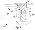
- the first part of the arrangement 500 comprises a member 510 in the form of a cantilever beam made of a ferromagnetic material attached by means of the threaded section 511 to the implanted fixture 520.
- the implant fixture can be a dental implant attached by a threaded section 512 in a section of a bone 530.
- the member 510 in this case is itself the detectable part 540.
- the beam 510 is brought into excitation by means of an external magnetic field 565 generated by the field generators 560.
- the testing apparatus 550 includes the probe 551 and the response analyzer unit 552.
- the probe can be part of the magnetic field generator.
- the probe 550 comprises a coil 553 for detecting interferences in the magnetic field 565.
- the analysing can be conducted as described in conjunction with the first example.
- the field generator can be a permanent magnet for generating a DC field or a coil for generating an AC filed.
- the probe may also be externally arranged.
- the transducers or gauges, and optionally also the beam may be coated, for example with an air-dry acrylic material, to protect the transducers during sterilization of the apparatus.
- the member may take a form other than a cantilever beam.
- the beam instead of being basically straight, could be generally U-shaped, and connected to the implant or abutment by its base.
- alternative detectors such UV, sound, and the like can also be used.
- the invention is limited to implants .
- the idea might be transferred to all small spaces wherein hold of an object such as screws, rivets, bolt or pin, is to be tested.
Landscapes
- Health & Medical Sciences (AREA)
- Life Sciences & Earth Sciences (AREA)
- General Health & Medical Sciences (AREA)
- Engineering & Computer Science (AREA)
- Biomedical Technology (AREA)
- Biophysics (AREA)
- Veterinary Medicine (AREA)
- Public Health (AREA)
- Animal Behavior & Ethology (AREA)
- Oral & Maxillofacial Surgery (AREA)
- Dentistry (AREA)
- Epidemiology (AREA)
- Surgery (AREA)
- Physics & Mathematics (AREA)
- Pathology (AREA)
- Heart & Thoracic Surgery (AREA)
- Medical Informatics (AREA)
- Molecular Biology (AREA)
- Radiology & Medical Imaging (AREA)
- Nuclear Medicine, Radiotherapy & Molecular Imaging (AREA)
- Prostheses (AREA)
- Dental Prosthetics (AREA)
- Dental Tools And Instruments Or Auxiliary Dental Instruments (AREA)
Claims (20)
- Verfahren zum Prüfen eines Implantats (120, 220, 520), das an einem Knochen (130, 230, 530) befestigt ist, wobei das Verfahren folgende Schritte umfasst:- Befestigen eines Bauteils (110, 210, 510) an dem Implantat vermittels eines Gewindeabschnittes,- Anregen des Bauteils,gekennzeichnet durch- Erzeugen der Anregung mit einem externen Magnetfeld,- berührungsfreies Detektieren einer Magnetfeldinterferenz des Bauteils, um wenigstens eine Resonanzfrequenz des Bauteils (110, 210, 510) während der Anregung zu detektieren, wenn das Bauteil an der Befestigung (120, 220, 510) befestigt ist; und- Analysieren der detektierten wenigstens einen Resonanzfrequenz vermittels eines Analysators, dessen Ausgabe ein Verhältnis einer Antwortspannung zu der Anregung darstellt, das einen Grad der Befestigung des Implantats (120, 220, 520) an dem Knochen bereitstellt.
- Verfahren gemäß Anspruch 1, das den Schritt aufweist, das Bauteil abnehmbar an der Befestigung zu befestigen.
- Verfahren gemäß Anspruch 1 oder 2, wobei das Bauteil (110, 120, 520) einen Auslegerbalken umfasst.
- Verfahren gemäß einem der vorhergehenden Ansprüche, wobei das Bauteil (110) einen magnetischen Teil (140) umfasst.
- Verfahren gemäß Anspruch 4, wobei die Resonanzfrequenz vermittels einer Spule (153) detektiert wird.
- Verfahren gemäß einem der Ansprüche 1 bis 3, wobei das Bauteil (510) aus einem ferromagnetischen Material hergestellt ist.
- Verfahren gemäß Anspruch 6, wobei die Resonanzfrequenz dadurch detektiert wird, dass das Bauteil ein Magnetfeld (565) stört.
- Verfahren gemäß Anspruch 3, wobei die Befestigung eine Gewindebohrung aufweist und der Auslegerbalken an oder in die Befestigung geschraubt ist.
- Verfahren gemäß einem der Ansprüche 1 bis 8, das den Schritt aufweist, die detektierte Resonanzfrequenz mit einem oder mehreren Werten für die Resonanzfrequenzen derselben oder ähnlicher Bauteile in Kontakt mit anderen Befestigungen zu vergleichen.
- Verfahren gemäß einem der Ansprüche 1 bis 9, das den Schritt aufweist, die detektierte Resonanzfrequenz mit einem oder mehreren zu verschiedenen Zeiten genommenen Werten für die Resonanzfrequenzen desselben oder ähnlichen Bauteils in Kontakt mit derselben Befestigung zu vergleichen.
- Verfahren gemäß Anspruch 1, das ein Ableiten einer Ausgabe aufweist, die das Verhältnis der Spannung des Antwortsignals zu der des Anregungssignals ist.
- Anordnung (500) zum Prüfen eines Implantats (520), das an einem Knochen (530) befestigt ist, wobei die Anordnung umfasst:- ein Bauteil (510), das dazu angepasst ist, abnehmbar an dem Implantat befestigt zu sein,- Detektionsmittel (550) zum Detektieren wenigstens einer Resonanzfrequenz des Bauteils, wenn dasselbe an dem Implantat befestigt ist,gekennzeichnet durch
einen Anregungserzeugungsteil, der ein Magnetfeld (565) zum Anregen des Bauteils erzeugt,
dass das Bauteil (510) einen magnetischen detektierbaren Teil (540) umfasst und
dass das Detektionsmittel (520) einen Detektor (553) zur berührungsfreien Detektion von Interferenzen des Magnetfeldes (565) umfasst. - Anordnung (500) gemäß Anspruch 12, wobei der Detektor (553) eine Spule (553) umfasst.
- Anordnung (500) gemäß einem der Ansprüche 12 bis 13, weiterhin einen Verstärker (154), einen Prozessor (155) und einen Datenspeicher (156) umfassend.
- Anordnung (500) gemäß Anspruch 12, wobei durch den Detektor (553) detektierte Signale durch den Verstärker (154) verstärkt werden und als ein zu analysierender Eingang angelegt werden; die analysierte Ausgabe, die ein Verhältnis einer Antwortspannung zu der Anregung darstellt, dem Prozessor zugeführt wird, der die Frequenzausgabe des Oszillators des Analysators variiert und die Ergebnisse in dem Datenspeicher (156) speichert.
- Anordnung (500) gemäß Anspruch 12, wobei der detektierbare Teil aus einem ferromagnetischen Material besteht.
- Anordnung (500) gemäß Anspruch 16, wobei der Detektor (550) eine Spule (553) zum Detektieren von Störungen in einem externen Magnetfeld umfasst.
- Anordnung (500) gemäß einem der Ansprüche 12 bis 17, wobei das Bauteil einen Auslegerbalken umfasst.
- Anordnung (500) gemäß Anspruch 18, wobei der Balken dazu angeordnet oder angepasst ist, bei einer Frequenz innerhalb des Bereiches von circa 1 bis 20 kHz, bevorzugt circa 1 bis 10 kHz und besonders bevorzugt in der Größenordnung von 8 KHz in Resonanz zu stehen.
- Anordnung (500) gemäß einem der Ansprüche 12 bis 19, wobei das Bauteil (510) ein Einwegteil ist.
Priority Applications (1)
| Application Number | Priority Date | Filing Date | Title |
|---|---|---|---|
| PL04749036T PL1641394T3 (pl) | 2003-06-19 | 2004-06-21 | Sposób i urządzenie związane z testowaniem implantów |
Applications Claiming Priority (2)
| Application Number | Priority Date | Filing Date | Title |
|---|---|---|---|
| SE0301825A SE0301825L (sv) | 2003-06-19 | 2003-06-19 | Metod och system vid implantattest |
| PCT/SE2004/000998 WO2004110272A1 (en) | 2003-06-19 | 2004-06-21 | Method and arrangement relating to testing objects |
Publications (2)
| Publication Number | Publication Date |
|---|---|
| EP1641394A1 EP1641394A1 (de) | 2006-04-05 |
| EP1641394B1 true EP1641394B1 (de) | 2012-08-08 |
Family
ID=27607388
Family Applications (1)
| Application Number | Title | Priority Date | Filing Date |
|---|---|---|---|
| EP04749036A Expired - Lifetime EP1641394B1 (de) | 2003-06-19 | 2004-06-21 | Verfahren und anordnung im zusammenhang mit der prüfung von implantaten |
Country Status (9)
| Country | Link |
|---|---|
| US (1) | US8979532B2 (de) |
| EP (1) | EP1641394B1 (de) |
| JP (1) | JP4806348B2 (de) |
| KR (1) | KR101302111B1 (de) |
| DK (1) | DK1641394T3 (de) |
| ES (1) | ES2392534T3 (de) |
| PL (1) | PL1641394T3 (de) |
| SE (2) | SE0301825L (de) |
| WO (1) | WO2004110272A1 (de) |
Cited By (2)
| Publication number | Priority date | Publication date | Assignee | Title |
|---|---|---|---|---|
| WO2016204684A1 (en) * | 2015-06-18 | 2016-12-22 | Osstell Ab | Implant stability measuring device and method |
| US11944452B2 (en) | 2017-03-10 | 2024-04-02 | University Of Washington | Methods and systems to measure and evaluate stability of medical implants |
Families Citing this family (16)
| Publication number | Priority date | Publication date | Assignee | Title |
|---|---|---|---|---|
| SE0301825L (sv) | 2003-06-19 | 2005-02-18 | Integration Diagnostics Ltd | Metod och system vid implantattest |
| US8448516B2 (en) * | 2006-08-17 | 2013-05-28 | Covenant Health | Apparatus and method for assessing percutaneous implant integrity |
| DE102006051032A1 (de) * | 2006-10-21 | 2008-04-30 | Fraunhofer-Gesellschaft zur Förderung der angewandten Forschung e.V. | System und Verfahren zur Bestimmung des Verankerungszustandes implantierter Endoprothesen |
| SE1001237A1 (sv) * | 2010-12-29 | 2012-06-30 | Ostell Ab | Anordning för kvalitetes provning av ett dentalt fäste |
| TWI546060B (zh) * | 2013-12-02 | 2016-08-21 | 國立中央大學 | 骨缺損檢測系統、裝置及方法 |
| KR101643586B1 (ko) * | 2015-02-12 | 2016-07-29 | 오스템임플란트 주식회사 | 치열 교정용 스크류 어댑터 |
| JP2017144061A (ja) * | 2016-02-17 | 2017-08-24 | 学校法人慶應義塾 | 整形外科用インプラントの設置強度評価方法、整形外科用インプラント、および整形外科治具 |
| GB2554456A (en) * | 2016-09-29 | 2018-04-04 | Osstell Ab | A probe |
| KR101838179B1 (ko) * | 2016-12-19 | 2018-04-26 | 주식회사 써지덴트 | 임플란트용 고정력 측정 장치 |
| JP7281770B2 (ja) * | 2017-09-14 | 2023-05-26 | 慶應義塾 | インプラント設置強度評価方法、インプラント設置強度評価装置、およびプログラム |
| DK3899486T3 (da) * | 2018-12-21 | 2022-09-26 | Tmd Friction Services Gmbh | Anordning og fremgangsmåde til beregning af mekaniske egenskaber ved et prøveemne |
| JP2020146072A (ja) * | 2019-03-11 | 2020-09-17 | 株式会社ナカニシ | 歯科用医療装置 |
| TWI729594B (zh) | 2019-11-27 | 2021-06-01 | 國立中央大學 | 檢測裝置 |
| US20210325437A1 (en) * | 2020-04-19 | 2021-10-21 | Research Electronics International, Llc | Cached Peak Graphical Display for Spectrum Analyzers |
| CN114948314A (zh) * | 2022-07-11 | 2022-08-30 | 长沙微笑美齿智能科技有限公司 | 一种用于检测植入牙槽骨种植体稳固度的传感装置及方法 |
| KR102824770B1 (ko) | 2022-10-13 | 2025-06-26 | 주식회사 덴티스 | 임플란트 동요도 측정장치 |
Citations (1)
| Publication number | Priority date | Publication date | Assignee | Title |
|---|---|---|---|---|
| US20020115944A1 (en) * | 1999-11-18 | 2002-08-22 | Emanuel Mendes | Systems and methods for monitoring wear and/or displacement of artificial joint members, vertebrae, segments of fractured bones and dental implants |
Family Cites Families (22)
| Publication number | Priority date | Publication date | Assignee | Title |
|---|---|---|---|---|
| US3292426A (en) * | 1963-07-26 | 1966-12-20 | Joseph A Mccann | Vibration detection device |
| US3355933A (en) * | 1964-03-16 | 1967-12-05 | Robert G Rowe | Resonance vibration testing apparatus |
| US4362511A (en) * | 1981-07-09 | 1982-12-07 | John Jacklich | J Bolt |
| US4511330A (en) * | 1981-11-18 | 1985-04-16 | Medical Magnetics, Inc. | Integrated oral magnetic osteogenic appliances |
| YU128990A (sh) | 1989-07-11 | 1993-05-28 | Warner-Lambert Co. | Preparati polimernih smeša koji sadrže destrukturisani skrob |
| GB9107700D0 (en) * | 1991-04-11 | 1991-05-29 | Imperial College | Testing implants |
| US5555884A (en) | 1992-12-16 | 1996-09-17 | Kabushiki Kaisha Egawa | Measuring method by using resonance of a resonance medium |
| US5518008A (en) | 1994-08-25 | 1996-05-21 | Spectral Sciences Research Corporation | Structural analyzer, in particular for medical implants |
| JP2863448B2 (ja) * | 1994-09-26 | 1999-03-03 | 哲生 宅野 | 歯の動揺度測定装置 |
| US6161046A (en) * | 1996-04-09 | 2000-12-12 | Maniglia; Anthony J. | Totally implantable cochlear implant for improvement of partial and total sensorineural hearing loss |
| JPH10201771A (ja) | 1997-01-20 | 1998-08-04 | Injietsukusu:Kk | 歯冠修復物 |
| US6034296A (en) * | 1997-03-11 | 2000-03-07 | Elvin; Niell | Implantable bone strain telemetry sensing system and method |
| WO1999046603A1 (en) | 1998-03-09 | 1999-09-16 | Otm Technologies, Ltd. | Optical translation measurement |
| WO1999058080A1 (en) * | 1998-05-08 | 1999-11-18 | Rose Emery S | Surface acoustic wave periodontal probe and method of detecting periodontal disease |
| SE9903304L (sv) * | 1999-09-16 | 2001-03-17 | Integration Diagnostics Ltd | Anordning och metod för implantat beläget i ben |
| EP1223862A4 (de) * | 1999-09-30 | 2004-10-20 | Vine Brook Res Corp | Implantierbarer mechanischer kräftesensor |
| US20020143268A1 (en) * | 2001-04-03 | 2002-10-03 | Neil Meredith | Bone implant testing |
| JP4160788B2 (ja) * | 2001-06-12 | 2008-10-08 | 株式会社吉田製作所 | 歯科用築造体を利用した生体情報計測・記録及び通信装置とこの装置の情報入出力を制御する情報制御方法 |
| DE50201594D1 (de) * | 2001-07-28 | 2004-12-23 | Aesculap Ag & Co Kg | Medizinisches implantatsystem |
| DE20112482U1 (de) * | 2001-07-28 | 2001-10-31 | Aesculap AG & Co. KG, 78532 Tuttlingen | Medizinisches Implantatsystem |
| SE0301825L (sv) | 2003-06-19 | 2005-02-18 | Integration Diagnostics Ltd | Metod och system vid implantattest |
| US20050026113A1 (en) * | 2003-07-30 | 2005-02-03 | Jiunn-Liang Chen | Micro-implantable apparatus and method for the stability assessment of a two-stage dental implant |
-
2003
- 2003-06-19 SE SE0301825A patent/SE0301825L/sv not_active Application Discontinuation
-
2004
- 2004-06-21 ES ES04749036T patent/ES2392534T3/es not_active Expired - Lifetime
- 2004-06-21 JP JP2006517049A patent/JP4806348B2/ja not_active Expired - Lifetime
- 2004-06-21 PL PL04749036T patent/PL1641394T3/pl unknown
- 2004-06-21 WO PCT/SE2004/000998 patent/WO2004110272A1/en not_active Ceased
- 2004-06-21 DK DK04749036.2T patent/DK1641394T3/da active
- 2004-06-21 EP EP04749036A patent/EP1641394B1/de not_active Expired - Lifetime
- 2004-06-21 KR KR1020057024381A patent/KR101302111B1/ko not_active Expired - Lifetime
- 2004-06-21 SE SE04749036T patent/SE1641394T5/xx unknown
-
2010
- 2010-12-29 US US12/980,717 patent/US8979532B2/en not_active Expired - Fee Related
Patent Citations (1)
| Publication number | Priority date | Publication date | Assignee | Title |
|---|---|---|---|---|
| US20020115944A1 (en) * | 1999-11-18 | 2002-08-22 | Emanuel Mendes | Systems and methods for monitoring wear and/or displacement of artificial joint members, vertebrae, segments of fractured bones and dental implants |
Cited By (2)
| Publication number | Priority date | Publication date | Assignee | Title |
|---|---|---|---|---|
| WO2016204684A1 (en) * | 2015-06-18 | 2016-12-22 | Osstell Ab | Implant stability measuring device and method |
| US11944452B2 (en) | 2017-03-10 | 2024-04-02 | University Of Washington | Methods and systems to measure and evaluate stability of medical implants |
Also Published As
| Publication number | Publication date |
|---|---|
| US8979532B2 (en) | 2015-03-17 |
| JP4806348B2 (ja) | 2011-11-02 |
| PL1641394T3 (pl) | 2013-01-31 |
| SE0301825L (sv) | 2005-02-18 |
| ES2392534T3 (es) | 2012-12-11 |
| JP2006527627A (ja) | 2006-12-07 |
| DK1641394T3 (da) | 2012-10-29 |
| KR101302111B1 (ko) | 2013-09-03 |
| WO2004110272A1 (en) | 2004-12-23 |
| US20110200965A1 (en) | 2011-08-18 |
| KR20060067926A (ko) | 2006-06-20 |
| SE0301825D0 (sv) | 2003-06-19 |
| SE1641394T5 (de) | 2016-02-02 |
| EP1641394A1 (de) | 2006-04-05 |
Similar Documents
| Publication | Publication Date | Title |
|---|---|---|
| EP1641394B1 (de) | Verfahren und anordnung im zusammenhang mit der prüfung von implantaten | |
| EP0579673B1 (de) | Implantateuntersuchung | |
| US20140072929A1 (en) | Method and arrangement relating to testing objects | |
| US8337428B2 (en) | Zero-crossing receiver for orthopedic parameter sensing | |
| US8391958B2 (en) | Method and arrangement relating to testing objects | |
| JPH10505519A (ja) | 特に医療インプラントに適した構造解析器 | |
| US20020143268A1 (en) | Bone implant testing | |
| JPH07508665A (ja) | 関節鏡検査用の押込装置及びその使用方法 | |
| EP3990886A1 (de) | Bestimmung der strukturellen eigenschaften eines objekts | |
| US20070270684A1 (en) | Method and Arrangement Relating to Testing Objects | |
| JP7281770B2 (ja) | インプラント設置強度評価方法、インプラント設置強度評価装置、およびプログラム | |
| WO2012091671A1 (en) | Dental attachment quality testing device | |
| US20200022652A1 (en) | A probe | |
| US8109876B1 (en) | Noninvasive technique for identification of structural integrity of Bjork Shiley convexo-concave mechanical heart valves | |
| Varini et al. | A device to test the primary stability in cementless hip arthroplasty through mechanical vibrations |
Legal Events
| Date | Code | Title | Description |
|---|---|---|---|
| PUAI | Public reference made under article 153(3) epc to a published international application that has entered the european phase |
Free format text: ORIGINAL CODE: 0009012 |
|
| 17P | Request for examination filed |
Effective date: 20060117 |
|
| AK | Designated contracting states |
Kind code of ref document: A1 Designated state(s): AT BE BG CH CY CZ DE DK EE ES FI FR GB GR HU IE IT LI LU MC NL PL PT RO SE SI SK TR |
|
| DAX | Request for extension of the european patent (deleted) | ||
| 17Q | First examination report despatched |
Effective date: 20101126 |
|
| RAP1 | Party data changed (applicant data changed or rights of an application transferred) |
Owner name: OSSTELL AB |
|
| GRAP | Despatch of communication of intention to grant a patent |
Free format text: ORIGINAL CODE: EPIDOSNIGR1 |
|
| RIN1 | Information on inventor provided before grant (corrected) |
Inventor name: PETTERSSON, ANDERS Inventor name: CAWLEY, PETER |
|
| GRAS | Grant fee paid |
Free format text: ORIGINAL CODE: EPIDOSNIGR3 |
|
| GRAA | (expected) grant |
Free format text: ORIGINAL CODE: 0009210 |
|
| AK | Designated contracting states |
Kind code of ref document: B1 Designated state(s): AT BE BG CH CY CZ DE DK EE ES FI FR GB GR HU IE IT LI LU MC NL PL PT RO SE SI SK TR |
|
| REG | Reference to a national code |
Ref country code: GB Ref legal event code: FG4D |
|
| REG | Reference to a national code |
Ref country code: AT Ref legal event code: REF Ref document number: 569295 Country of ref document: AT Kind code of ref document: T Effective date: 20120815 Ref country code: CH Ref legal event code: EP |
|
| REG | Reference to a national code |
Ref country code: IE Ref legal event code: FG4D |
|
| REG | Reference to a national code |
Ref country code: DE Ref legal event code: R096 Ref document number: 602004038835 Country of ref document: DE Effective date: 20121011 |
|
| REG | Reference to a national code |
Ref country code: CH Ref legal event code: NV Representative=s name: BOVARD AG |
|
| REG | Reference to a national code |
Ref country code: DK Ref legal event code: T3 |
|
| REG | Reference to a national code |
Ref country code: NL Ref legal event code: T3 |
|
| REG | Reference to a national code |
Ref country code: SE Ref legal event code: TRGR |
|
| REG | Reference to a national code |
Ref country code: ES Ref legal event code: FG2A Ref document number: 2392534 Country of ref document: ES Kind code of ref document: T3 Effective date: 20121211 |
|
| PG25 | Lapsed in a contracting state [announced via postgrant information from national office to epo] |
Ref country code: CY Free format text: LAPSE BECAUSE OF FAILURE TO SUBMIT A TRANSLATION OF THE DESCRIPTION OR TO PAY THE FEE WITHIN THE PRESCRIBED TIME-LIMIT Effective date: 20120808 Ref country code: FI Free format text: LAPSE BECAUSE OF FAILURE TO SUBMIT A TRANSLATION OF THE DESCRIPTION OR TO PAY THE FEE WITHIN THE PRESCRIBED TIME-LIMIT Effective date: 20120808 |
|
| REG | Reference to a national code |
Ref country code: PL Ref legal event code: T3 |
|
| PG25 | Lapsed in a contracting state [announced via postgrant information from national office to epo] |
Ref country code: PT Free format text: LAPSE BECAUSE OF FAILURE TO SUBMIT A TRANSLATION OF THE DESCRIPTION OR TO PAY THE FEE WITHIN THE PRESCRIBED TIME-LIMIT Effective date: 20121210 Ref country code: SI Free format text: LAPSE BECAUSE OF FAILURE TO SUBMIT A TRANSLATION OF THE DESCRIPTION OR TO PAY THE FEE WITHIN THE PRESCRIBED TIME-LIMIT Effective date: 20120808 Ref country code: GR Free format text: LAPSE BECAUSE OF FAILURE TO SUBMIT A TRANSLATION OF THE DESCRIPTION OR TO PAY THE FEE WITHIN THE PRESCRIBED TIME-LIMIT Effective date: 20121109 |
|
| PG25 | Lapsed in a contracting state [announced via postgrant information from national office to epo] |
Ref country code: CZ Free format text: LAPSE BECAUSE OF FAILURE TO SUBMIT A TRANSLATION OF THE DESCRIPTION OR TO PAY THE FEE WITHIN THE PRESCRIBED TIME-LIMIT Effective date: 20120808 Ref country code: RO Free format text: LAPSE BECAUSE OF FAILURE TO SUBMIT A TRANSLATION OF THE DESCRIPTION OR TO PAY THE FEE WITHIN THE PRESCRIBED TIME-LIMIT Effective date: 20120808 Ref country code: EE Free format text: LAPSE BECAUSE OF FAILURE TO SUBMIT A TRANSLATION OF THE DESCRIPTION OR TO PAY THE FEE WITHIN THE PRESCRIBED TIME-LIMIT Effective date: 20120808 |
|
| PG25 | Lapsed in a contracting state [announced via postgrant information from national office to epo] |
Ref country code: SK Free format text: LAPSE BECAUSE OF FAILURE TO SUBMIT A TRANSLATION OF THE DESCRIPTION OR TO PAY THE FEE WITHIN THE PRESCRIBED TIME-LIMIT Effective date: 20120808 |
|
| PLBE | No opposition filed within time limit |
Free format text: ORIGINAL CODE: 0009261 |
|
| STAA | Information on the status of an ep patent application or granted ep patent |
Free format text: STATUS: NO OPPOSITION FILED WITHIN TIME LIMIT |
|
| 26N | No opposition filed |
Effective date: 20130510 |
|
| PG25 | Lapsed in a contracting state [announced via postgrant information from national office to epo] |
Ref country code: BG Free format text: LAPSE BECAUSE OF FAILURE TO SUBMIT A TRANSLATION OF THE DESCRIPTION OR TO PAY THE FEE WITHIN THE PRESCRIBED TIME-LIMIT Effective date: 20121108 |
|
| REG | Reference to a national code |
Ref country code: DE Ref legal event code: R097 Ref document number: 602004038835 Country of ref document: DE Effective date: 20130510 |
|
| PG25 | Lapsed in a contracting state [announced via postgrant information from national office to epo] |
Ref country code: MC Free format text: LAPSE BECAUSE OF FAILURE TO SUBMIT A TRANSLATION OF THE DESCRIPTION OR TO PAY THE FEE WITHIN THE PRESCRIBED TIME-LIMIT Effective date: 20120808 |
|
| REG | Reference to a national code |
Ref country code: IE Ref legal event code: MM4A |
|
| PG25 | Lapsed in a contracting state [announced via postgrant information from national office to epo] |
Ref country code: IE Free format text: LAPSE BECAUSE OF NON-PAYMENT OF DUE FEES Effective date: 20130621 |
|
| PG25 | Lapsed in a contracting state [announced via postgrant information from national office to epo] |
Ref country code: TR Free format text: LAPSE BECAUSE OF FAILURE TO SUBMIT A TRANSLATION OF THE DESCRIPTION OR TO PAY THE FEE WITHIN THE PRESCRIBED TIME-LIMIT Effective date: 20120808 |
|
| REG | Reference to a national code |
Ref country code: FR Ref legal event code: PLFP Year of fee payment: 12 |
|
| PG25 | Lapsed in a contracting state [announced via postgrant information from national office to epo] |
Ref country code: LU Free format text: LAPSE BECAUSE OF NON-PAYMENT OF DUE FEES Effective date: 20130621 Ref country code: HU Free format text: LAPSE BECAUSE OF FAILURE TO SUBMIT A TRANSLATION OF THE DESCRIPTION OR TO PAY THE FEE WITHIN THE PRESCRIBED TIME-LIMIT; INVALID AB INITIO Effective date: 20040621 |
|
| REG | Reference to a national code |
Ref country code: SE Ref legal event code: RPOT |
|
| REG | Reference to a national code |
Ref country code: FR Ref legal event code: PLFP Year of fee payment: 13 |
|
| REG | Reference to a national code |
Ref country code: FR Ref legal event code: PLFP Year of fee payment: 14 |
|
| PGFP | Annual fee paid to national office [announced via postgrant information from national office to epo] |
Ref country code: SE Payment date: 20170621 Year of fee payment: 14 |
|
| REG | Reference to a national code |
Ref country code: SE Ref legal event code: INVA |
|
| PG25 | Lapsed in a contracting state [announced via postgrant information from national office to epo] |
Ref country code: SE Free format text: LAPSE BECAUSE OF NON-PAYMENT OF DUE FEES Effective date: 20180316 |
|
| PGFP | Annual fee paid to national office [announced via postgrant information from national office to epo] |
Ref country code: NL Payment date: 20230612 Year of fee payment: 20 Ref country code: IT Payment date: 20230612 Year of fee payment: 20 Ref country code: FR Payment date: 20230627 Year of fee payment: 20 Ref country code: DK Payment date: 20230612 Year of fee payment: 20 Ref country code: DE Payment date: 20230612 Year of fee payment: 20 |
|
| PGFP | Annual fee paid to national office [announced via postgrant information from national office to epo] |
Ref country code: PL Payment date: 20230609 Year of fee payment: 20 Ref country code: AT Payment date: 20230615 Year of fee payment: 20 |
|
| PGFP | Annual fee paid to national office [announced via postgrant information from national office to epo] |
Ref country code: BE Payment date: 20230612 Year of fee payment: 20 |
|
| PGFP | Annual fee paid to national office [announced via postgrant information from national office to epo] |
Ref country code: GB Payment date: 20230613 Year of fee payment: 20 Ref country code: ES Payment date: 20230922 Year of fee payment: 20 Ref country code: CH Payment date: 20230702 Year of fee payment: 20 |
|
| REG | Reference to a national code |
Ref country code: DE Ref legal event code: R071 Ref document number: 602004038835 Country of ref document: DE |
|
| REG | Reference to a national code |
Ref country code: DK Ref legal event code: EUP Expiry date: 20240621 |
|
| REG | Reference to a national code |
Ref country code: NL Ref legal event code: MK Effective date: 20240620 |
|
| REG | Reference to a national code |
Ref country code: CH Ref legal event code: PL Ref country code: ES Ref legal event code: FD2A Effective date: 20240628 |
|
| PG25 | Lapsed in a contracting state [announced via postgrant information from national office to epo] |
Ref country code: GB Free format text: LAPSE BECAUSE OF EXPIRATION OF PROTECTION Effective date: 20240620 |
|
| REG | Reference to a national code |
Ref country code: BE Ref legal event code: MK Effective date: 20240621 |
|
| PG25 | Lapsed in a contracting state [announced via postgrant information from national office to epo] |
Ref country code: ES Free format text: LAPSE BECAUSE OF EXPIRATION OF PROTECTION Effective date: 20240622 |
|
| PG25 | Lapsed in a contracting state [announced via postgrant information from national office to epo] |
Ref country code: GB Free format text: LAPSE BECAUSE OF EXPIRATION OF PROTECTION Effective date: 20240620 Ref country code: ES Free format text: LAPSE BECAUSE OF EXPIRATION OF PROTECTION Effective date: 20240622 |
|
| REG | Reference to a national code |
Ref country code: AT Ref legal event code: MK07 Ref document number: 569295 Country of ref document: AT Kind code of ref document: T Effective date: 20240621 |