EP1642291B1 - Abnehmereinheit-homing-mechanismus für eine plattenlaufwerkeinheit - Google Patents
Abnehmereinheit-homing-mechanismus für eine plattenlaufwerkeinheit Download PDFInfo
- Publication number
- EP1642291B1 EP1642291B1 EP04744385A EP04744385A EP1642291B1 EP 1642291 B1 EP1642291 B1 EP 1642291B1 EP 04744385 A EP04744385 A EP 04744385A EP 04744385 A EP04744385 A EP 04744385A EP 1642291 B1 EP1642291 B1 EP 1642291B1
- Authority
- EP
- European Patent Office
- Prior art keywords
- engagement
- transmission member
- pickup unit
- disk drive
- drive unit
- Prior art date
- Legal status (The legal status is an assumption and is not a legal conclusion. Google has not performed a legal analysis and makes no representation as to the accuracy of the status listed.)
- Expired - Lifetime
Links
- 230000007246 mechanism Effects 0.000 title claims abstract description 25
- 230000005540 biological transmission Effects 0.000 claims abstract description 57
- 230000009471 action Effects 0.000 claims description 6
- 230000003287 optical effect Effects 0.000 claims description 3
- 238000000034 method Methods 0.000 description 8
- 230000008901 benefit Effects 0.000 description 6
- 238000004519 manufacturing process Methods 0.000 description 4
- 238000001514 detection method Methods 0.000 description 2
- 230000008859 change Effects 0.000 description 1
- 239000004020 conductor Substances 0.000 description 1
- 238000006073 displacement reaction Methods 0.000 description 1
- 230000000977 initiatory effect Effects 0.000 description 1
- 239000000463 material Substances 0.000 description 1
Images


Classifications
-
- G—PHYSICS
- G11—INFORMATION STORAGE
- G11B—INFORMATION STORAGE BASED ON RELATIVE MOVEMENT BETWEEN RECORD CARRIER AND TRANSDUCER
- G11B7/00—Recording or reproducing by optical means, e.g. recording using a thermal beam of optical radiation by modifying optical properties or the physical structure, reproducing using an optical beam at lower power by sensing optical properties; Record carriers therefor
- G11B7/08—Disposition or mounting of heads or light sources relatively to record carriers
- G11B7/085—Disposition or mounting of heads or light sources relatively to record carriers with provision for moving the light beam into, or out of, its operative position or across tracks, otherwise than during the transducing operation, e.g. for adjustment or preliminary positioning or track change or selection
-
- G—PHYSICS
- G11—INFORMATION STORAGE
- G11B—INFORMATION STORAGE BASED ON RELATIVE MOVEMENT BETWEEN RECORD CARRIER AND TRANSDUCER
- G11B7/00—Recording or reproducing by optical means, e.g. recording using a thermal beam of optical radiation by modifying optical properties or the physical structure, reproducing using an optical beam at lower power by sensing optical properties; Record carriers therefor
- G11B7/08—Disposition or mounting of heads or light sources relatively to record carriers
- G11B7/085—Disposition or mounting of heads or light sources relatively to record carriers with provision for moving the light beam into, or out of, its operative position or across tracks, otherwise than during the transducing operation, e.g. for adjustment or preliminary positioning or track change or selection
- G11B7/0857—Arrangements for mechanically moving the whole head
- G11B7/08582—Sled-type positioners
-
- G—PHYSICS
- G11—INFORMATION STORAGE
- G11B—INFORMATION STORAGE BASED ON RELATIVE MOVEMENT BETWEEN RECORD CARRIER AND TRANSDUCER
- G11B21/00—Head arrangements not specific to the method of recording or reproducing
- G11B21/02—Driving or moving of heads
-
- G—PHYSICS
- G11—INFORMATION STORAGE
- G11B—INFORMATION STORAGE BASED ON RELATIVE MOVEMENT BETWEEN RECORD CARRIER AND TRANSDUCER
- G11B21/00—Head arrangements not specific to the method of recording or reproducing
- G11B21/02—Driving or moving of heads
- G11B21/022—Programmed access in sequence to indexed parts of operating record carriers
- G11B21/025—Programmed access in sequence to indexed parts of operating record carriers of rotating discs
-
- G—PHYSICS
- G11—INFORMATION STORAGE
- G11B—INFORMATION STORAGE BASED ON RELATIVE MOVEMENT BETWEEN RECORD CARRIER AND TRANSDUCER
- G11B5/00—Recording by magnetisation or demagnetisation of a record carrier; Reproducing by magnetic means; Record carriers therefor
- G11B5/48—Disposition or mounting of heads or head supports relative to record carriers ; arrangements of heads, e.g. for scanning the record carrier to increase the relative speed
- G11B5/54—Disposition or mounting of heads or head supports relative to record carriers ; arrangements of heads, e.g. for scanning the record carrier to increase the relative speed with provision for moving the head into or out of its operative position or across tracks
- G11B5/55—Track change, selection or acquisition by displacement of the head
-
- G—PHYSICS
- G11—INFORMATION STORAGE
- G11B—INFORMATION STORAGE BASED ON RELATIVE MOVEMENT BETWEEN RECORD CARRIER AND TRANSDUCER
- G11B5/00—Recording by magnetisation or demagnetisation of a record carrier; Reproducing by magnetic means; Record carriers therefor
- G11B5/48—Disposition or mounting of heads or head supports relative to record carriers ; arrangements of heads, e.g. for scanning the record carrier to increase the relative speed
- G11B5/54—Disposition or mounting of heads or head supports relative to record carriers ; arrangements of heads, e.g. for scanning the record carrier to increase the relative speed with provision for moving the head into or out of its operative position or across tracks
- G11B5/55—Track change, selection or acquisition by displacement of the head
- G11B5/5521—Track change, selection or acquisition by displacement of the head across disk tracks
Definitions
- the invention relates to a disk drive unit for a disk.
- Disk drive units of this type are known in many embodiments thereof, and generally comprise a mounting plate, a spindle motor assembly, a pickup unit for reading and/or writing data on the disk, and a slide mechanism which is adapted to move the pickup unit along the surface of the disk between a home position and a read and/or write position.
- the slide is moved by a transmission assembly comprising a gear rack operatively coupled with the slide and in engagement with a gear wheel which is driven by a DC motor.
- disk drive units of this type In order to detect the home position of the pickup unit, disk drive units of this type generally comprise an additional limit switch which is adapted to stop the DC motor when the home position is reached.
- the use of a limit switch within a disk drive unit leads to additional assembly and material costs, which comprise in general the costs for a switch, some resistors and connectors, an I/O port and additional space on the circuit board.
- the disk drive unit comprises a pickup unit mounted to a slide of a slide mechanism, which slide mechanism is adapted to move the pickup unit along the disk between a home position and a read and/or write position, the slide mechanism comprising a driven first transmission member which is operatively connected to the slide for moving the sledge, and a driving second transmission member which is only in engagement with the first transmission member when the pickup unit is in the read and/or write position, and wherein the pickup unit and the second transmission member comprise engagement members which are adapted to come into engagement at least when the second transmission member is not in engagement with the first transmission member so as to move the pickup unit away from the home position, which movement causes the first and second transmission members to engage.
- the first and the second transmission member are disengaged when the pickup unit reaches its home position, whereby the movement of the pickup unit is stopped.
- the transmission assembly of the disk drive unit is adapted to stop the movement of the slide when the pickup unit reaches its home position, so that a limit switch is no longer necessary for detecting the home position of the pickup unit, which is cost-effective.
- the invention provides engagement members at the second transmission member and the pickup unit.
- the features as defined in claim 2 have the advantage that the engagement members of the pickup unit and the second transmission member do not interfere with the movement of the pickup unit when it is moved to its home position.
- the feature as defined in claim 3 has the advantage that a cam is a very simple and low-cost means for initiating the engagement of the engagement members of the pickup unit and the second transmission member. Moreover, as a movable bearing plate coupled to the actuator of the pickup unit is generally used in disk drive units, the addition of the cam is the only change to be made to the bearing plate in order to obtain the disk drive unit according to the invention, which is cost-effective.
- the invention also relates to a device for reading and/or writing information, such as data, from/on an optical disk.
- the device according to the invention is provided with the disk drive unit according to the invention.
- This disk drive unit 1 may be used in a device for reading and/or writing data on a disk, such as a compact disk player, which is adapted to read and/or write compact disks for audio and/or video by means of an optical or magnetic reading and/or writing member.
- the preferred embodiment of the disk drive unit comprises a mounting plate 2 and a spindle motor assembly 3 on the mounting plate which is adapted to support and to rotate a disk when positioned on the spindle motor assembly 3.
- a pickup unit 4 is provided which comprises a laser assembly 5.
- the disk is rotated and the laser assembly 5 is translated along the disk in a radial direction with respect to the disk.
- the focusing of the laser assembly 5 in a perpendicular direction with respect to the disk is performed by a focus actuator mechanism within the laser assembly (not shown).
- the movement of the laser assembly in a radial direction along and with respect to the disk is performed by a slide mechanism 6 which roughly positions the pickup unit with respect to the disk and by a positioning mechanism 7 of the pickup unit 4 which performs the fine positioning of the laser assembly 5.
- the slide mechanism 6 of the preferred embodiment of the disk drive unit 1 comprises a slide 8, and the pickup unit 4 is mounted on the slide 8.
- the positioning mechanism 7 of the pickup unit 4 comprises a bearing plate 9 which is pivotably mounted to the slide 8 by means of a pivot pin 10.
- the positioning mechanism 7 further comprises an actuator 11 which is operatively connected to the bearing plate 9 and the slide 8.
- the actuator 11 is adapted to rotate the bearing plate 9 around the pivot pin 10 with respect to the slide 8.
- the laser assembly 5 is mounted to the bearing plate 9 at a distance from the pivot pin 10 such that the laser assembly 5 is slightly moved along the disk due to the rotation of the bearing plate 9.
- the slide mechanism 6 of the preferred embodiment of the disk drive unit 1 is adapted to move the pickup unit 4 to a home position, which is near the spindle motor assembly 3 as shown in Figs. 1 and 2, and an operating position where the laser assembly 5 of the pickup unit 4 is enabled to read and/or write the data on the disk.
- the home position of the pickup unit 4 is the starting point from which a read and/or write sequence of the disk is initiated.
- the slide mechanism 6 comprises a first and a second transmission member, wherein the first transmission member is a gear rack 12 mounted to the slide 8 and the second transmission member is a gear wheel 13 rotatably mounted to the mounting plate 2.
- the gear rack 12 is adapted to come into engagement with the gear wheel 13.
- the preferred embodiment of the disk drive unit 1 comprises a DC motor 14 which is adapted to rotate the gear wheel 13 by means of a series of gearwheels 15.
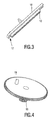
- the gear rack 12 of the preferred embodiment of the disk drive unit 1 is shown in more detail in Fig 3.
- the gear rack 12 is formed on a mounting member 16 in order to be mounted to the slide 8.
- the mounting member 16 further comprises a freewheel section 17 provided at one end of the mounting member 16.
- the gear rack 12 is positioned at the mounting member 16 such that the gear wheel 13 is in engagement with the gear rack 12 when the pickup unit is in its read and/or write position, and such that the gear wheel 13 is positioned at the freewheel section 17 when the pickup unit 4 is in its home position.
- the freewheel section 17 is not strictly required and the part containing the freewheel section may therefore be omitted so that the gear rack is just shorter.
- the slide mechanism 6 will work properly when the gear wheel 13 and the gear rack 12 are disengaged with the pickup unit 4 in its home position due to the limited length and the position of the gear rack 12 with respect to the slide 8 and the gear wheel 13.
- the bearing plate 9 of the pickup unit 4 of the preferred embodiment of the disk drive unit 1 comprises a cam 18 as an engagement member.
- the cam 18 is movable due to the action of the actuator 11 too.
- the gear wheel 13 of the preferred embodiment of the disk drive unit 1 is provided with a protrusion 19 as an engagement member.
- the protrusion 19 is positioned such that it is enabled to come into engagement with the cam 18 of the pickup unit 4 only when the actuator 11 has moved the cam 18 towards the gear wheel 13 by rotating the bearing plate 9. As a result, the cam 18 and the protrusion 19 do not interfere with the movements of the pickup unit 4 when the pickup unit 4 is moved to its home position.
- the preferred embodiment of the disk drive unit 1 further comprises a control unit (not shown) which is connected to the spindle motor assembly 3, to the laser assembly 5, to the actuator 11, and to the DC motor 14 (by means of electrical conductors, not shown).
- the control unit is adapted to power and control at least the above-mentioned electrical members.
- the control unit After reading and/or writing of the data on the disk, the control unit applies a constant voltage to the DC motor 14 of the slide mechanism 6 during a fixed time period.
- the voltage is provided such that the gear wheel 13 is rotated in the direction indicated by arrow 20.
- the pickup unit 4 mounted on the slide 8 is translated towards its home position.
- the gear rack 12 and the gear wheel 13 are disengaged due to the limited length and the position of the gear rack 12 with respect to the slide 8 and the gear wheel 13, whereby the movement of the pickup unit 4 is stopped and the gear wheel 13 is enabled to rotate freely about its axis at the position of the freewheel section 17 on the mounting member 16.
- the fixed time period of the voltage applied to the DC motor 14 of the slide mechanism 6 is based on the time which is needed for moving the pickup unit 4 from its outermost position towards its home position. As the gear rack 12 and the gear wheel 13 are disengaged when the pickup unit 4 reaches its home position, any remaining rotations of the gear wheel 13 in the case the pickup unit 4 has not been moved from its outermost position will not have any impact on the slide mechanism 6.
- a start-up procedure is initiated when the fixed time period has passed and a new read and/or write sequence is desired. This start-up procedure is necessary for bringing the gear rack 12 and the gear wheel 13 back into engagement in order to enable the laser assembly 5 of the pickup unit 4 to read and/or write the data on the disk.
- control unit powers the actuator 11 of the pickup unit 4 such that the cam 18 of the pickup unit 4 is brought into a position where it is enabled to come into engagement with the protrusion 19 on the gear wheel 13.
- the control unit also causes a series of voltage pulses to be applied to the DC motor 14 of the slide mechanism 6 such that the gear wheel 13 rotates stepwise in a direction opposite to arrow 20.
- the duration of each voltage pulse is such that the gear wheel 13 performs approximately half a revolution per voltage pulse.
- the control unit also starts focusing of the laser assembly 5.
- the laser assembly 5 is turned on in order to detect the information area of the disk.
- the control unit determines whether the laser assembly 5 has detected the information area of the disk.
- the gear rack 12 and the gear wheel 13 must be properly engaged and the start-up procedure is stopped. In general, the gear rack 12 and the gear wheel 13 will come into engagement within two or three half rotations of the gear wheel 13.
- the sequence of applied voltage pulses is limited, preferably to six pulses.
- the engagement of the gear rack 12 and the gear wheel 13 is detected by the laser assembly 5 of the pickup unit 4, so that the pickup unit 4 is able to function as a detecting member, without the need for an additional component.
- the movement of the pickup unit 4 is advantageously stopped at its home position due to the limited length and the position of the gear rack 12 with respect to the slide 8 and the gear wheel 13, and that the pickup unit 4 is moved away from its home position by the cam 18 on the pickup unit 4 and the protrusion 19 on the gear wheel 13 and by the action of the actuator 11 of the pickup unit 4, during all of which the control unit powers and controls the rotation of the gear wheel 13 and the action of the actuator 11.
- a limit switch for the detection of the home position of the pickup unit 4 is not required, which leads to a saving in manufacturing cost of the disk drive unit 1.
- the gear rack 12 As the gear rack 12, the gear wheel 13 provided with the protrusion 19, and the cam 18 provided on the pickup unit 4 are very simple to manufacture, the manufacturing costs of these means are relatively low.
- the engagement member of the pickup unit is not limited to a cam and that the engagement member of the second transmission member is not limited to a protrusion provided on the second transmission member.
- the engagement members may be any kind of cooperating members, such as brushes or the like, as long as the pickup unit is pushed away from its home position by the movement of the second transmission member.
- first and the second transmission member are not limited to a gear wheel and a gear rack.
- Any set of transmission members may be provided, such as a running surface driven by a wheel or gear wheels comprising free running sections and operatively connected to the pickup unit in order to move the pickup unit.
Landscapes
- Moving Of Heads (AREA)
- Feeding And Guiding Record Carriers (AREA)
- Moving Of The Head For Recording And Reproducing By Optical Means (AREA)
- Supporting Of Heads In Record-Carrier Devices (AREA)
Claims (13)
- Plattenlaufwerkseinheit (1) für eine Platte, wobei die Plattenlaufwerkseinheit (1) eine Abtasteinheit (4) umfasst, die an einem Schlitten (8) eines Schlittenmechanismus (6) befestigt ist, wobei der Schlittenmechanismus (6) eingerichtet ist, um die Abtasteinheit (4) entlang der Platte zwischen einer Ausgangsposition und einer Lese- und/oder Schreibposition zu bewegen, wobei der Schlittenmechanismus (6) ein angetriebenes erstes Kraftübertragungselement (12) umfasst, das betriebsfähig mit dem Schlitten (8) verbunden ist, um den Schlitten (8) zu bewegen, sowie ein antreibendes zweites Kraftübertragungselement (13), das nur im Eingriff mit dem ersten Kraftübertragungselement (12) steht, wenn sich die Abtasteinheit (4) in der Lese- und/oder Schreibposition befindet, und wobei die Abtasteinheit (4) und das zweite Kraftübertragungselement (13) Eingriffselemente (18, 19) umfassen, die eingerichtet sind, um zumindest dann in Eingriff zu kommen, wenn das zweite Kraftübertragungselement (13) nicht im Eingriff mit dem ersten Kraftübertragungselement (12) steht, sodass die Abtasteinheit (4) aus der Ausgangsposition bewegt wird, wobei die Bewegung bewirkt, dass das erste und zweite Kraftübertragungselement (12, 13) in Eingriff gebracht werden.
- Plattenlaufwerkseinheit (1) nach Anspruch 1, bei der das Eingriffselement (18) der Abtasteinheit (4) betriebsfähig mit einem Aktuator (11) der Abtasteinheit (4) gekoppelt ist und bei der das Eingriffselement (18) der Abtasteinheit (4) eingerichtet ist, um infolge der Aktion des Aktuators (11) der Abtasteinheit (4) mit dem Eingriffselement (19) des zweiten Kraftübertragungselements (13) in Eingriff zu kommen.
- Plattenlaufwerkseinheit (1) nach Anspruch 2, bei der das Eingriffselement der Abtasteinheit ein Nocken (18) an der Lagerplatte (9) der Abtasteinheit (4) ist, wobei die Lagerplatte (9) betriebsfähig mit dem Aktuator (11) der Abtasteinheit (4) gekoppelt ist und durch die Aktion des Aktuators (11) der Abtasteinheit (4) beweglich, vorzugsweise drehbar um einen Schwenkzapfen (10), ist, um den Nocken (18) in eine Position zu bewegen, in der dieser in Eingriff mit dem Eingriffselement (19) des zweiten Kraftübertragungselements (13) kommen kann.
- Plattenlaufwerkseinheit (1) nach einem der vorhergehenden Ansprüche, bei der das zweite Kraftübertragungselement (13) ein Zahnrad (13) ist.
- Plattenlaufwerkseinheit (1) nach einem der vorhergehenden Ansprüche, bei der das Eingriffselement (19) des zweiten Kraftübertragungselements (13) ein Vorsprung (19) ist, der am zweiten Kraftübertragungselement (13) in einer solchen Position vorgesehen ist, dass das Kraftübertragungselement in Eingriff mit dem Eingriffselement (18) der Abtasteinheit (4) kommen kann.
- Plattenlaufwerkseinheit (1) nach Anspruch 4 oder 5, bei der das erste Kraftübertragungselement (12) eine Zahnstange (12) ist, die so positioniert ist, dass die Zahnstange (12) im Eingriff mit dem Zahnrad (13) steht, wenn sich die Abtasteinheit (4) in ihrer Lese- und/oder Schreibposition befindet, und dass die Zahnstange (12) nicht im Eingriff mit dem Zahnrad (13) steht, wenn sich die Abtasteinheit (4) in ihrer Ausgangsposition befindet.
- Plattenlaufwerkseinheit (1) nach einem der Ansprüche 3 bis 6, bei der der Eingriff der Eingriffselemente (18, 19) der Abtasteinheit (4) und des zweiten Kraftübertragungselements (13) durch eine Bewegung des zweiten Kraftübertragungselements (13) und die gleichzeitige Bewegung des Eingriffselements (18) der Abtasteinheit (4) in die Position bewirkt wird, in der es in Eingriff mit dem Eingriffselement (19) des zweiten Kraftübertragungselements (13) kommen kann.
- Plattenlaufwerkseinheit (1) nach einem der vorhergehenden Ansprüche, die eine Steuereinheit umfasst, die so programmiert ist, dass der Antrieb des zweiten Kraftübertragungselements (13) aus einer Sequenz schrittweiser Antriebsbewegungen besteht, wobei die Sequenz gestoppt wird, wenn das erste und das zweite Kraftübertragungselement (12, 13) im Eingriff stehen oder wenn eine vorgegebene Anzahl von Antriebsbewegungen erreicht ist.
- Plattenlaufwerkseinheit (1) nach einem der vorhergehenden Ansprüche, bei der der Eingriff des ersten und des zweiten Kraftübertragungselements (12, 13) durch ein Erkennungselement erkannt wird.
- Plattenlaufwerkseinheit (1) nach Anspruch 9, bei der das Erkennungselement durch die Abtasteinheit (4) gebildet wird.
- Plattenlaufwerkseinheit (1) nach Anspruch 10, bei der die Steuereinheit so programmiert ist, dass die Antriebsbewegung des zweiten Kraftübertragungselements (13) gestoppt wird, wenn die Abtasteinheit (4) durch Erkennen einer Oberfläche einer in der Plattenlaufwerkseinheit (1) eingelegten Platte den Eingriff des ersten und des zweiten Kraftübertragungselements (12, 13) erkennt.
- Plattenlaufwerkseinheit (1) nach einem der vorhergehenden Ansprüche, bei der das zweite Kraftübertragungselement (13) betriebsfähig mit einem Motor (14) zum Antreiben des zweiten Kraftübertragungselements (13) verbunden ist.
- Einrichtung zum Lesen und/oder Schreiben von Informationen von einer/auf eine optische Platte, die mit der Plattenlaufwerkseinheit nach einem der vorhergehenden Ansprüche versehen ist.
Priority Applications (1)
| Application Number | Priority Date | Filing Date | Title |
|---|---|---|---|
| EP04744385A EP1642291B1 (de) | 2003-06-27 | 2004-06-23 | Abnehmereinheit-homing-mechanismus für eine plattenlaufwerkeinheit |
Applications Claiming Priority (3)
| Application Number | Priority Date | Filing Date | Title |
|---|---|---|---|
| EP03101927 | 2003-06-27 | ||
| PCT/IB2004/050978 WO2005001834A1 (en) | 2003-06-27 | 2004-06-23 | Pickup unit homing mechanism for a disk drive unit |
| EP04744385A EP1642291B1 (de) | 2003-06-27 | 2004-06-23 | Abnehmereinheit-homing-mechanismus für eine plattenlaufwerkeinheit |
Publications (2)
| Publication Number | Publication Date |
|---|---|
| EP1642291A1 EP1642291A1 (de) | 2006-04-05 |
| EP1642291B1 true EP1642291B1 (de) | 2007-12-26 |
Family
ID=33547761
Family Applications (1)
| Application Number | Title | Priority Date | Filing Date |
|---|---|---|---|
| EP04744385A Expired - Lifetime EP1642291B1 (de) | 2003-06-27 | 2004-06-23 | Abnehmereinheit-homing-mechanismus für eine plattenlaufwerkeinheit |
Country Status (8)
| Country | Link |
|---|---|
| US (1) | US7398538B2 (de) |
| EP (1) | EP1642291B1 (de) |
| JP (1) | JP4805821B2 (de) |
| KR (1) | KR101077857B1 (de) |
| CN (1) | CN100454428C (de) |
| AT (1) | ATE382181T1 (de) |
| DE (1) | DE602004010909T2 (de) |
| WO (1) | WO2005001834A1 (de) |
Families Citing this family (2)
| Publication number | Priority date | Publication date | Assignee | Title |
|---|---|---|---|---|
| CN2651892Y (zh) * | 2003-07-08 | 2004-10-27 | 鸿富锦精密工业(深圳)有限公司 | 光学读/写头进给机构 |
| CN1897148A (zh) * | 2005-07-15 | 2007-01-17 | 鸿富锦精密工业(深圳)有限公司 | 信息记录/再现装置 |
Family Cites Families (18)
| Publication number | Priority date | Publication date | Assignee | Title |
|---|---|---|---|---|
| US4697259A (en) | 1983-10-11 | 1987-09-29 | Nippon Gakki Seizo Kabushiki Kaisha | Disc automatically setting device of a disc player |
| JPH0646473B2 (ja) * | 1987-11-20 | 1994-06-15 | 三洋電機株式会社 | ディスクの自動装着装置 |
| JP3057269B2 (ja) * | 1991-08-27 | 2000-06-26 | ソニー株式会社 | 光学ピックアップ移動装置 |
| US5617395A (en) | 1993-11-11 | 1997-04-01 | Daewoo Electronics Co., Ltd. | Disc loading apparatus for a front loading disc player |
| JP3511668B2 (ja) * | 1994-02-25 | 2004-03-29 | ソニー株式会社 | ディスクローディング装置 |
| JP3320906B2 (ja) * | 1994-06-30 | 2002-09-03 | アルパイン株式会社 | ディスク装置 |
| JPH0896481A (ja) * | 1994-09-22 | 1996-04-12 | Sony Corp | ディスク記録再生装置 |
| KR0137539B1 (ko) * | 1994-12-29 | 1998-05-15 | 배순훈 | 광디스크플레이어의 트레이이송장치(disc tray loading mechanism of optical disc player) |
| DE19623124A1 (de) | 1996-06-10 | 1997-12-11 | Eastman Kodak Co | Vorrichtung zur Entnahme eines Plattenhalters aus und/oder Rückgabe an ein auswechselbares Magazin |
| US6345027B1 (en) | 1996-10-22 | 2002-02-05 | Matsushita Electric Industrial Co., Ltd. | Disk driving apparatus |
| DE19753897A1 (de) * | 1997-12-05 | 1999-06-10 | Thomson Brandt Gmbh | Kraftübertragungssystem mit einem Zahnrad und einer Zahnstange |
| JP2963084B1 (ja) | 1998-03-30 | 1999-10-12 | 三洋電機株式会社 | 歯車機構及び該歯車機構を具えた収納装置 |
| TW440046U (en) | 1999-07-01 | 2001-06-07 | Ind Tech Res Inst | Sheet-carrying mechanism of disk type data storage device |
| JP2001297544A (ja) * | 2000-04-14 | 2001-10-26 | Kenwood Corp | 光ディスク装置 |
| WO2002029802A1 (en) | 2000-09-29 | 2002-04-11 | Matsushita Electric Industrial Co., Ltd. | Optical disk device |
| JP2002175659A (ja) * | 2000-09-29 | 2002-06-21 | Matsushita Electric Ind Co Ltd | 光ディスク装置 |
| JP2002140849A (ja) * | 2000-10-31 | 2002-05-17 | Clarion Co Ltd | ディスクプレーヤ |
| JP2002358664A (ja) * | 2002-05-30 | 2002-12-13 | Matsushita Electric Ind Co Ltd | 光ピックアップ移動装置 |
-
2004
- 2004-06-23 DE DE602004010909T patent/DE602004010909T2/de not_active Expired - Lifetime
- 2004-06-23 AT AT04744385T patent/ATE382181T1/de not_active IP Right Cessation
- 2004-06-23 CN CNB2004800180085A patent/CN100454428C/zh not_active Expired - Fee Related
- 2004-06-23 WO PCT/IB2004/050978 patent/WO2005001834A1/en not_active Ceased
- 2004-06-23 KR KR1020057024922A patent/KR101077857B1/ko not_active Expired - Fee Related
- 2004-06-23 US US10/562,280 patent/US7398538B2/en not_active Expired - Fee Related
- 2004-06-23 EP EP04744385A patent/EP1642291B1/de not_active Expired - Lifetime
- 2004-06-23 JP JP2006516748A patent/JP4805821B2/ja not_active Expired - Fee Related
Also Published As
| Publication number | Publication date |
|---|---|
| KR101077857B1 (ko) | 2011-10-31 |
| ATE382181T1 (de) | 2008-01-15 |
| CN100454428C (zh) | 2009-01-21 |
| US20060156323A1 (en) | 2006-07-13 |
| DE602004010909T2 (de) | 2008-12-11 |
| EP1642291A1 (de) | 2006-04-05 |
| DE602004010909D1 (de) | 2008-02-07 |
| WO2005001834A1 (en) | 2005-01-06 |
| JP4805821B2 (ja) | 2011-11-02 |
| US7398538B2 (en) | 2008-07-08 |
| CN1813308A (zh) | 2006-08-02 |
| JP2007519124A (ja) | 2007-07-12 |
| KR20060025570A (ko) | 2006-03-21 |
Similar Documents
| Publication | Publication Date | Title |
|---|---|---|
| US5761182A (en) | Optical recording and reproducing apparatus | |
| US5513157A (en) | Loading apparatus for recording medium and method for controlling the same | |
| US5128918A (en) | Disk loading device for disk player | |
| KR19990056375A (ko) | 디스크 플레이어 | |
| EP1642291B1 (de) | Abnehmereinheit-homing-mechanismus für eine plattenlaufwerkeinheit | |
| US20020024910A1 (en) | Disk drive apparatus | |
| JPH11203757A (ja) | 光ディスク装置 | |
| KR950007443B1 (ko) | 멀티디스크플레이어의 틸팅장치 | |
| JP2765592B2 (ja) | デイスクローデイング装置 | |
| JP3587310B2 (ja) | 記録媒体ローディング装置および記録媒体搬送制御方法 | |
| EP0833322B1 (de) | Antriebsvorrichtung für ein Aufzeichnungsmedium | |
| US6741542B2 (en) | Disk device | |
| US5872752A (en) | Apparatus for recording and/or reproducing disk-like recording medium | |
| US7249362B2 (en) | Disk chucking mechanism and disk drive device with increased positional accuracy | |
| JPH0222850Y2 (de) | ||
| JPH0388170A (ja) | マルチディスクプレーヤ | |
| KR0130608B1 (ko) | 광디스크플레이어 | |
| JP3157332B2 (ja) | ディスクプレーヤーの回転数検出装置 | |
| KR910003457Y1 (ko) | Cd/cdv용 턴테이블의 90°회전장치 | |
| JP2002032950A (ja) | ディスク選択式ディスク装置 | |
| KR100587252B1 (ko) | 포터블형 광 디스크 플레이어 | |
| KR20040108267A (ko) | 광디스크 드라이브 | |
| KR100505704B1 (ko) | 광디스크 드라이브 | |
| JP2002032938A (ja) | 光磁気記録再生装置 | |
| JP2001297545A (ja) | 回転体の駆動装置および回転体の駆動方法 |
Legal Events
| Date | Code | Title | Description |
|---|---|---|---|
| PUAI | Public reference made under article 153(3) epc to a published international application that has entered the european phase |
Free format text: ORIGINAL CODE: 0009012 |
|
| 17P | Request for examination filed |
Effective date: 20060127 |
|
| AK | Designated contracting states |
Kind code of ref document: A1 Designated state(s): AT BE BG CH CY CZ DE DK EE ES FI FR GB GR HU IE IT LI LU MC NL PL PT RO SE SI SK TR |
|
| DAX | Request for extension of the european patent (deleted) | ||
| GRAP | Despatch of communication of intention to grant a patent |
Free format text: ORIGINAL CODE: EPIDOSNIGR1 |
|
| GRAS | Grant fee paid |
Free format text: ORIGINAL CODE: EPIDOSNIGR3 |
|
| GRAA | (expected) grant |
Free format text: ORIGINAL CODE: 0009210 |
|
| AK | Designated contracting states |
Kind code of ref document: B1 Designated state(s): AT BE BG CH CY CZ DE DK EE ES FI FR GB GR HU IE IT LI LU MC NL PL PT RO SE SI SK TR |
|
| REG | Reference to a national code |
Ref country code: GB Ref legal event code: FG4D |
|
| REG | Reference to a national code |
Ref country code: IE Ref legal event code: FG4D |
|
| REG | Reference to a national code |
Ref country code: CH Ref legal event code: EP |
|
| REF | Corresponds to: |
Ref document number: 602004010909 Country of ref document: DE Date of ref document: 20080207 Kind code of ref document: P |
|
| PG25 | Lapsed in a contracting state [announced via postgrant information from national office to epo] |
Ref country code: SE Free format text: LAPSE BECAUSE OF FAILURE TO SUBMIT A TRANSLATION OF THE DESCRIPTION OR TO PAY THE FEE WITHIN THE PRESCRIBED TIME-LIMIT Effective date: 20080326 Ref country code: LI Free format text: LAPSE BECAUSE OF FAILURE TO SUBMIT A TRANSLATION OF THE DESCRIPTION OR TO PAY THE FEE WITHIN THE PRESCRIBED TIME-LIMIT Effective date: 20071226 Ref country code: CH Free format text: LAPSE BECAUSE OF FAILURE TO SUBMIT A TRANSLATION OF THE DESCRIPTION OR TO PAY THE FEE WITHIN THE PRESCRIBED TIME-LIMIT Effective date: 20071226 |
|
| PG25 | Lapsed in a contracting state [announced via postgrant information from national office to epo] |
Ref country code: PL Free format text: LAPSE BECAUSE OF FAILURE TO SUBMIT A TRANSLATION OF THE DESCRIPTION OR TO PAY THE FEE WITHIN THE PRESCRIBED TIME-LIMIT Effective date: 20071226 Ref country code: SI Free format text: LAPSE BECAUSE OF FAILURE TO SUBMIT A TRANSLATION OF THE DESCRIPTION OR TO PAY THE FEE WITHIN THE PRESCRIBED TIME-LIMIT Effective date: 20071226 Ref country code: FI Free format text: LAPSE BECAUSE OF FAILURE TO SUBMIT A TRANSLATION OF THE DESCRIPTION OR TO PAY THE FEE WITHIN THE PRESCRIBED TIME-LIMIT Effective date: 20071226 Ref country code: NL Free format text: LAPSE BECAUSE OF FAILURE TO SUBMIT A TRANSLATION OF THE DESCRIPTION OR TO PAY THE FEE WITHIN THE PRESCRIBED TIME-LIMIT Effective date: 20071226 |
|
| NLV1 | Nl: lapsed or annulled due to failure to fulfill the requirements of art. 29p and 29m of the patents act | ||
| REG | Reference to a national code |
Ref country code: CH Ref legal event code: PL |
|
| PG25 | Lapsed in a contracting state [announced via postgrant information from national office to epo] |
Ref country code: AT Free format text: LAPSE BECAUSE OF FAILURE TO SUBMIT A TRANSLATION OF THE DESCRIPTION OR TO PAY THE FEE WITHIN THE PRESCRIBED TIME-LIMIT Effective date: 20071226 |
|
| PG25 | Lapsed in a contracting state [announced via postgrant information from national office to epo] |
Ref country code: CZ Free format text: LAPSE BECAUSE OF FAILURE TO SUBMIT A TRANSLATION OF THE DESCRIPTION OR TO PAY THE FEE WITHIN THE PRESCRIBED TIME-LIMIT Effective date: 20071226 Ref country code: ES Free format text: LAPSE BECAUSE OF FAILURE TO SUBMIT A TRANSLATION OF THE DESCRIPTION OR TO PAY THE FEE WITHIN THE PRESCRIBED TIME-LIMIT Effective date: 20080406 |
|
| ET | Fr: translation filed | ||
| PG25 | Lapsed in a contracting state [announced via postgrant information from national office to epo] |
Ref country code: SK Free format text: LAPSE BECAUSE OF FAILURE TO SUBMIT A TRANSLATION OF THE DESCRIPTION OR TO PAY THE FEE WITHIN THE PRESCRIBED TIME-LIMIT Effective date: 20071226 Ref country code: RO Free format text: LAPSE BECAUSE OF FAILURE TO SUBMIT A TRANSLATION OF THE DESCRIPTION OR TO PAY THE FEE WITHIN THE PRESCRIBED TIME-LIMIT Effective date: 20071226 Ref country code: BE Free format text: LAPSE BECAUSE OF FAILURE TO SUBMIT A TRANSLATION OF THE DESCRIPTION OR TO PAY THE FEE WITHIN THE PRESCRIBED TIME-LIMIT Effective date: 20071226 |
|
| PG25 | Lapsed in a contracting state [announced via postgrant information from national office to epo] |
Ref country code: PT Free format text: LAPSE BECAUSE OF FAILURE TO SUBMIT A TRANSLATION OF THE DESCRIPTION OR TO PAY THE FEE WITHIN THE PRESCRIBED TIME-LIMIT Effective date: 20080526 |
|
| PG25 | Lapsed in a contracting state [announced via postgrant information from national office to epo] |
Ref country code: DK Free format text: LAPSE BECAUSE OF FAILURE TO SUBMIT A TRANSLATION OF THE DESCRIPTION OR TO PAY THE FEE WITHIN THE PRESCRIBED TIME-LIMIT Effective date: 20071226 |
|
| PLBE | No opposition filed within time limit |
Free format text: ORIGINAL CODE: 0009261 |
|
| STAA | Information on the status of an ep patent application or granted ep patent |
Free format text: STATUS: NO OPPOSITION FILED WITHIN TIME LIMIT |
|
| 26N | No opposition filed |
Effective date: 20080929 |
|
| PG25 | Lapsed in a contracting state [announced via postgrant information from national office to epo] |
Ref country code: MC Free format text: LAPSE BECAUSE OF NON-PAYMENT OF DUE FEES Effective date: 20080630 Ref country code: GR Free format text: LAPSE BECAUSE OF FAILURE TO SUBMIT A TRANSLATION OF THE DESCRIPTION OR TO PAY THE FEE WITHIN THE PRESCRIBED TIME-LIMIT Effective date: 20080327 |
|
| PG25 | Lapsed in a contracting state [announced via postgrant information from national office to epo] |
Ref country code: BG Free format text: LAPSE BECAUSE OF FAILURE TO SUBMIT A TRANSLATION OF THE DESCRIPTION OR TO PAY THE FEE WITHIN THE PRESCRIBED TIME-LIMIT Effective date: 20080326 Ref country code: IE Free format text: LAPSE BECAUSE OF NON-PAYMENT OF DUE FEES Effective date: 20080623 Ref country code: EE Free format text: LAPSE BECAUSE OF FAILURE TO SUBMIT A TRANSLATION OF THE DESCRIPTION OR TO PAY THE FEE WITHIN THE PRESCRIBED TIME-LIMIT Effective date: 20071226 |
|
| PG25 | Lapsed in a contracting state [announced via postgrant information from national office to epo] |
Ref country code: CY Free format text: LAPSE BECAUSE OF FAILURE TO SUBMIT A TRANSLATION OF THE DESCRIPTION OR TO PAY THE FEE WITHIN THE PRESCRIBED TIME-LIMIT Effective date: 20071226 |
|
| PG25 | Lapsed in a contracting state [announced via postgrant information from national office to epo] |
Ref country code: HU Free format text: LAPSE BECAUSE OF FAILURE TO SUBMIT A TRANSLATION OF THE DESCRIPTION OR TO PAY THE FEE WITHIN THE PRESCRIBED TIME-LIMIT Effective date: 20080627 Ref country code: LU Free format text: LAPSE BECAUSE OF NON-PAYMENT OF DUE FEES Effective date: 20080623 |
|
| PG25 | Lapsed in a contracting state [announced via postgrant information from national office to epo] |
Ref country code: TR Free format text: LAPSE BECAUSE OF FAILURE TO SUBMIT A TRANSLATION OF THE DESCRIPTION OR TO PAY THE FEE WITHIN THE PRESCRIBED TIME-LIMIT Effective date: 20071226 |
|
| PG25 | Lapsed in a contracting state [announced via postgrant information from national office to epo] |
Ref country code: IT Free format text: LAPSE BECAUSE OF NON-PAYMENT OF DUE FEES Effective date: 20080630 |
|
| PGFP | Annual fee paid to national office [announced via postgrant information from national office to epo] |
Ref country code: GB Payment date: 20110630 Year of fee payment: 8 |
|
| GBPC | Gb: european patent ceased through non-payment of renewal fee |
Effective date: 20120623 |
|
| PG25 | Lapsed in a contracting state [announced via postgrant information from national office to epo] |
Ref country code: GB Free format text: LAPSE BECAUSE OF NON-PAYMENT OF DUE FEES Effective date: 20120623 |
|
| REG | Reference to a national code |
Ref country code: DE Ref legal event code: R082 Ref document number: 602004010909 Country of ref document: DE Representative=s name: VOLMER, GEORG, DIPL.-ING., DE |
|
| REG | Reference to a national code |
Ref country code: DE Ref legal event code: R082 Ref document number: 602004010909 Country of ref document: DE Representative=s name: MEISSNER, BOLTE & PARTNER GBR, DE Effective date: 20140328 Ref country code: DE Ref legal event code: R082 Ref document number: 602004010909 Country of ref document: DE Representative=s name: MEISSNER BOLTE PATENTANWAELTE RECHTSANWAELTE P, DE Effective date: 20140328 Ref country code: DE Ref legal event code: R081 Ref document number: 602004010909 Country of ref document: DE Owner name: KONINKLIJKE PHILIPS N.V., NL Free format text: FORMER OWNER: KONINKLIJKE PHILIPS ELECTRONICS N.V., EINDHOVEN, NL Effective date: 20140328 Ref country code: DE Ref legal event code: R082 Ref document number: 602004010909 Country of ref document: DE Representative=s name: VOLMER, GEORG, DIPL.-ING., DE Effective date: 20140328 |
|
| REG | Reference to a national code |
Ref country code: FR Ref legal event code: CA Effective date: 20141126 Ref country code: FR Ref legal event code: CD Owner name: KONINKLIJKE PHILIPS N.V., NL Effective date: 20141126 |
|
| REG | Reference to a national code |
Ref country code: FR Ref legal event code: PLFP Year of fee payment: 12 |
|
| PGFP | Annual fee paid to national office [announced via postgrant information from national office to epo] |
Ref country code: DE Payment date: 20150831 Year of fee payment: 12 |
|
| PGFP | Annual fee paid to national office [announced via postgrant information from national office to epo] |
Ref country code: FR Payment date: 20150630 Year of fee payment: 12 |
|
| REG | Reference to a national code |
Ref country code: DE Ref legal event code: R082 Ref document number: 602004010909 Country of ref document: DE Representative=s name: MEISSNER, BOLTE & PARTNER GBR, DE Ref country code: DE Ref legal event code: R082 Ref document number: 602004010909 Country of ref document: DE Representative=s name: MEISSNER BOLTE PATENTANWAELTE RECHTSANWAELTE P, DE |
|
| REG | Reference to a national code |
Ref country code: DE Ref legal event code: R119 Ref document number: 602004010909 Country of ref document: DE |
|
| REG | Reference to a national code |
Ref country code: FR Ref legal event code: ST Effective date: 20170228 |
|
| PG25 | Lapsed in a contracting state [announced via postgrant information from national office to epo] |
Ref country code: FR Free format text: LAPSE BECAUSE OF NON-PAYMENT OF DUE FEES Effective date: 20160630 Ref country code: DE Free format text: LAPSE BECAUSE OF NON-PAYMENT OF DUE FEES Effective date: 20170103 |