EP1642655B1 - Vorrichtung zur Reinigung der eingetauchten Strukturen - Google Patents
Vorrichtung zur Reinigung der eingetauchten Strukturen Download PDFInfo
- Publication number
- EP1642655B1 EP1642655B1 EP05108943A EP05108943A EP1642655B1 EP 1642655 B1 EP1642655 B1 EP 1642655B1 EP 05108943 A EP05108943 A EP 05108943A EP 05108943 A EP05108943 A EP 05108943A EP 1642655 B1 EP1642655 B1 EP 1642655B1
- Authority
- EP
- European Patent Office
- Prior art keywords
- rope
- rotating members
- rotating member
- rotating
- attachments
- Prior art date
- Legal status (The legal status is an assumption and is not a legal conclusion. Google has not performed a legal analysis and makes no representation as to the accuracy of the status listed.)
- Not-in-force
Links
- XLYOFNOQVPJJNP-UHFFFAOYSA-N water Substances O XLYOFNOQVPJJNP-UHFFFAOYSA-N 0.000 claims abstract description 29
- 239000000463 material Substances 0.000 claims description 11
- -1 polyethylene Polymers 0.000 claims description 8
- 229920013716 polyethylene resin Polymers 0.000 claims description 8
- 239000004576 sand Substances 0.000 claims description 7
- 239000004698 Polyethylene Substances 0.000 claims description 6
- 229920000573 polyethylene Polymers 0.000 claims description 6
- 238000000071 blow moulding Methods 0.000 claims description 5
- 238000003466 welding Methods 0.000 claims description 5
- 229920003002 synthetic resin Polymers 0.000 claims description 3
- 239000000057 synthetic resin Substances 0.000 claims description 3
- 239000000835 fiber Substances 0.000 claims 1
- 238000000465 moulding Methods 0.000 claims 1
- 238000010276 construction Methods 0.000 description 20
- 239000002184 metal Substances 0.000 description 7
- 229920003023 plastic Polymers 0.000 description 7
- 239000004033 plastic Substances 0.000 description 7
- 230000007797 corrosion Effects 0.000 description 6
- 238000005260 corrosion Methods 0.000 description 6
- 229910000831 Steel Inorganic materials 0.000 description 5
- 238000004519 manufacturing process Methods 0.000 description 5
- 238000000034 method Methods 0.000 description 5
- 239000010959 steel Substances 0.000 description 5
- 230000007774 longterm Effects 0.000 description 4
- 230000001681 protective effect Effects 0.000 description 3
- 239000007787 solid Substances 0.000 description 3
- 238000005299 abrasion Methods 0.000 description 2
- 229910001220 stainless steel Inorganic materials 0.000 description 2
- 239000010935 stainless steel Substances 0.000 description 2
- 239000000126 substance Substances 0.000 description 2
- 239000002341 toxic gas Substances 0.000 description 2
- 229920000742 Cotton Polymers 0.000 description 1
- 239000004677 Nylon Substances 0.000 description 1
- 239000004743 Polypropylene Substances 0.000 description 1
- BZHJMEDXRYGGRV-UHFFFAOYSA-N Vinyl chloride Chemical compound ClC=C BZHJMEDXRYGGRV-UHFFFAOYSA-N 0.000 description 1
- 230000003247 decreasing effect Effects 0.000 description 1
- 238000000151 deposition Methods 0.000 description 1
- 230000002542 deteriorative effect Effects 0.000 description 1
- 150000002013 dioxins Chemical class 0.000 description 1
- 239000006260 foam Substances 0.000 description 1
- 230000004927 fusion Effects 0.000 description 1
- 239000007769 metal material Substances 0.000 description 1
- 229920001778 nylon Polymers 0.000 description 1
- 229920001155 polypropylene Polymers 0.000 description 1
- 229920005989 resin Polymers 0.000 description 1
- 239000011347 resin Substances 0.000 description 1
- 230000000630 rising effect Effects 0.000 description 1
- 239000013535 sea water Substances 0.000 description 1
- 235000015170 shellfish Nutrition 0.000 description 1
- 239000002352 surface water Substances 0.000 description 1
- 229920002994 synthetic fiber Polymers 0.000 description 1
- 239000012209 synthetic fiber Substances 0.000 description 1
Images



Classifications
-
- B—PERFORMING OPERATIONS; TRANSPORTING
- B08—CLEANING
- B08B—CLEANING IN GENERAL; PREVENTION OF FOULING IN GENERAL
- B08B9/00—Cleaning hollow articles by methods or apparatus specially adapted thereto
- B08B9/02—Cleaning pipes or tubes or systems of pipes or tubes
- B08B9/023—Cleaning the external surfaces
-
- B—PERFORMING OPERATIONS; TRANSPORTING
- B08—CLEANING
- B08B—CLEANING IN GENERAL; PREVENTION OF FOULING IN GENERAL
- B08B17/00—Methods preventing fouling
- B08B17/02—Preventing deposition of fouling or of dust
-
- B—PERFORMING OPERATIONS; TRANSPORTING
- B08—CLEANING
- B08B—CLEANING IN GENERAL; PREVENTION OF FOULING IN GENERAL
- B08B7/00—Cleaning by methods not provided for in a single other subclass or a single group in this subclass
- B08B7/02—Cleaning by methods not provided for in a single other subclass or a single group in this subclass by distortion, beating, or vibration of the surface to be cleaned
-
- B—PERFORMING OPERATIONS; TRANSPORTING
- B63—SHIPS OR OTHER WATERBORNE VESSELS; RELATED EQUIPMENT
- B63B—SHIPS OR OTHER WATERBORNE VESSELS; EQUIPMENT FOR SHIPPING
- B63B59/00—Hull protection specially adapted for vessels; Cleaning devices specially adapted for vessels
- B63B59/06—Cleaning devices for hulls
- B63B59/08—Cleaning devices for hulls of underwater surfaces while afloat
-
- E—FIXED CONSTRUCTIONS
- E02—HYDRAULIC ENGINEERING; FOUNDATIONS; SOIL SHIFTING
- E02B—HYDRAULIC ENGINEERING
- E02B17/00—Artificial islands mounted on piles or like supports, e.g. platforms on raisable legs or offshore constructions; Construction methods therefor
- E02B17/0017—Means for protecting offshore constructions
Definitions
- the present invention relates to an apparatus for removing attachments deposited on underwater structures; particularly, relating to an apparatus for removing marine organisms deposited on underwater structures, such as stanchions extending underwater, particularly in the sea, and for preventing possible deposits thereafter.
- Another apparatus which comprises a plurality of hollow bodies each respectively having lugs at both ends, a protective ring provided on each hollow body in a rotatable manner, and a socket ring further provided on the protective ring in a fixed manner.
- the hollow bodies each having a protection ring and a socket ring are connected together to make a large circle, and set out around structures, such as piles, so that the apparatus makes contact with the surface of the structures with the aid of wave force to remove attachments, such as marine organisms, deposited thereon (See Japanese Patent Preliminarily Publication Nos. 2000-8339 and 2003-1998).
- the protective ring and the socket ring rotate in a united manner, so that the impact when the apparatus impinge upon the structures is absorbed and thus the wear of both the structures and the apparatus is decreased.
- the apparatus shows excellent performance in removing the attachments deposited on underwater structures. In this manner, it is an elementary requirement that the part of the apparatus where contact is made with the structure is rotatable, in order to improve the durability and the deposit removing ability of the apparatus.
- the apparatus for removing deposits disclosed in Japanese Patent Preliminarily Publication No. 10-219652 is arranged such that a wire having some floating bodies makes contact with the surface of steel piles or concrete piles in order to remove the attachments deposited thereon. Since the apparatus is left for a comparatively long term, it is required to use metal wire, such as that made of stainless steel. However, galvanic corrosion occurs on such metal wire after setting it out underwater, and it therefore cannot stand long term use. Further, when the wire is partially damaged, for example, by corrosion, it is necessary to change the wire as a whole, requiring hefty work at great expense. Furthermore, the metal wire should be hard and thin which causes abrasion to the concrete piles over an extended period of time deteriorating the strength thereof.
- the rotatable protection ring and the socket ring are provided on the outer surface of each hollow body to be connected together.
- These members i.e. the protection ring, the socket ring and the hollow body, need to be separately prepared and then assembled. This makes the manufacturing cost of the apparatus high, and the assembly work complicated.
- plural members are connected together and it is necessary to prepare many of the apparatuses at a single site, therefore manufacturing costs increase and heavy assembly work is required. Since the apparatuses are connected together with the aid of nuts and bolts, and on average 15 ⁇ 40 apparatuses are used at a single site, a large amount of labor is required.
- plane lugs are provided at both ends of the hollow body; and the bodies are connected together in such a manner that the lugs are superimposed on one another with the aid of nuts and bolts.
- an outer force is applied to the superimposed lugs in a perpendicular direction, it is difficult to allow release of the outer force. This causes the problem of the apparatus becoming brittle in structure.
- a soft vinyl chloride is used for the material of the apparatus, causing a toxic gas to generate freely when the apparatus is incinerated for disposal.
- JP-A-2000 8339 discloses a removing device for sea organism in accordance with the preamble of claim 1.
- the present invention has for its purpose to provide an apparatus for removing attachments deposited on underwater structures, according to which manufacturing and assembly of the apparatus can be easily carried out, no abrasion of the structures occurs after setting the apparatus on the structures; deposits can be removed in an effective manner; a high durability is given; and it is friendly to the environment.
- the apparatus for removing attachments deposited on underwater structures is set out around the structures so as to be on the surface or underwater, and the apparatus is naturally wafted on the surface of water or underwater where repeated contact occurs with the structures to remove the deposits thereon and to further prevent attachments such as marine organisms being deposited thereon in the future.
- the apparatus comprises a rope (first rope) arranged around or on the surface of said structures and at least one or more first rotating members through which said first rope extends so as to allow free rotation of the members about the rope .
- the apparatus has an aspect that at least one part of said rotating member is hollow.
- the apparatus is such that the apparatus further comprises a second rope connected to said first rope and extended in a direction substantially perpendicular to the extended direction of said first rope, with at least one or more second rotating members having a breakthrough through which said second rope extends so as to freely rotate tho second rotating members about the second rope underwater.
- the apparatus is such that said second rotating member has a closed structure in which heavy material, such as sand or water, is contained.
- said second rotating members may have two or more openings through which water flows into the hollow portion when the rotating member is underwater.
- the apparatus has still another aspect that said apparatus comprises a third rope being connected to the lower end of said second ropes and extended in a direction perpendicular to the extending direction of the second rope; and at least one second rotating member is threaded with the third rope through the breakthrough of the second rotating member.
- two or more rotating members are provided on the first to third ropes, and cylindrical collars each having an inner diameter sufficiently larger than the diameter of the ropes but smaller than the diameter of the rotating members be arranged around the ropes at each space between the adjacent rotating members.
- said first or second rotating members have an ellipsoid or rugby ball shape, and have a breakthrough for inserting the relevant rope in its longitudinal direction.
- a protrusion is provided on at least one part of the rotating surface area of said rotating member.
- said protrusion comprises a plurality of ridges which are evenly spaced apart and that extend in a direction perpendicular to the rotating direction of the rotating member, i.e. in the longitudinal direction of the rotating member.
- Said rotating members are manufactured either by the process of blow-molding polyethylene resin or by fitting and/or welding a few molded polyethylene parts to complete the rotating member.
- said ropes are prepared by twisting synthetic fibers made of polyethylene, etc.
- said first and/or third ropes have ring shape end portions, and that both ends of the ropes are connected together in such a manner that the end portions are superimposed together and then connected together with the aid of a bobbin-shaped connector, respectively.
- a rope is used to connect the rotating members, no galvanic corrosion occurs as does with the conventional metal wire, so the durability of the apparatus is improved.
- a rope has the further advantage that underwater structures are not physically damaged, because the rope is softer than the metal wire.
- a rope can be bent in all directions, outer forces exerted on the apparatus can be released in a suitable manner.
- the apparatus is constructed such that each rotating member as a whole is rotatable about the rope, so the apparatus can be manufactured and assembled much more easily and simply in comparison to the conventional apparatus where a rotatable protection ring or a socket ring is separately provided on the outer side of the hollowed or solid body.
- the rotating member as long as at least one part of the rotating member is arranged to be hollowed, it is not necessary to provide any additional floats to the rotating members. Therefore, manufacturing and labor costs for assembly of the rotating member can be saved.
- At least one or more second ropes are connected to the first rope in a vertically extended manner and at least one or more rotating members (second rotating members) each having a breakthrough, through which the second rope passes, are arranged to be rotatable about the second rope underwater. That is to say, a plurality of the apparatuses are connected in a vertical direction, so that the attachments deposited on the piles extended in a vertical direction underwater can be removed on a large scale.
- the second rotating member may be arranged such that sand or water is enclosed inside of the rotating member, and/or two or more openings penetrate the rotating members so that water can flow through the hollow of the second rotating member.
- the buoyancy of the rotating members is lost making it possible for the rotating members to waft underwater. Therefore, attachments deposited underwater on the surface of the piles can be effectively removed and can be prevented from being deposited thereafter.
- the apparatus further comprises a third rope that is connected to the lower ends of the second ropes extended in a direction almost parallel to the extended direction of the first rope, and with at least one second rotating member threaded by the third rope.
- the second ropes extend in an up/down direction in a stable manner. It can be expected to remove and prevent attachments with the rotating members rotating around the third rope, so that attachments deposited on the surface of underwater piles can be removed more efficiently.
- collars are provided between the abutted rotating members, having an inner diameter sufficiently larger than the diameter of the ropes but smaller than the diameter of the rotating members.
- the collars impinge on the right and left side rotating members with the aid of natural forces, such as waves, so that the attachment of marine organisms onto the rotating members can be effectively prevented.
- each rotating member has an ellipsoid shape (or a rugby ball shape) and a breakthrough is provided in its longitudinal direction for inserting the rope therethrough. Therefore, the attachments deposited on the edge portion of the rectangular shaped structure can be removed more efficiently in comparison to the use of round rotating members.
- a protruding portion is provided on at least one part of the area of the rotating member where the rotating member is apt to impinge against the structure.
- the edge of the protruding portion allows the effective shaving off of attachments while the durability of the apparatus is improved with the thickened part of the protruding portion.
- the rotating members can be manufactured by the process of blow-molding polyethylene resin; or by fitting and/or welding together the two or three parts that constitute the rotating member. According to this aspect, the rotating members can be manufactured and assembled easily, and it is possible to reduce the generation of toxic gas when incinerating the members for disposal. After use, the rotating members may also be re-cycled as a plastic material.
- the ropes may be prepared by twisting a synthetic resin, such as polyethylene, so desired features, i.e. light weight, softness and strength can be attained. It should be noted that a polyethylene resin is easy to re-use and therefore, eco-friendly.
- the ends of the first and third ropes have ring-shape portions, and that the ring-shaped ends are superimposed and held by means of a bobbin shaped fastening, so that a tight fastening can be realized for a long term and thus the durability of the apparatus is improved.
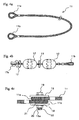
- Fig. 1 is a schematic view showing the construction of the first embodiment of the apparatus for removing attachments deposited on underwater structures according to the invention.
- the apparatus 1 is provided around a constructional pile 2 (structure), which extends from the bottom of the sea, like a bridge pile.
- structure 2 is shown with a dotted line.
- the surface of the water is not shown in the figure, but it is assumed that the apparatus 1 is floating on the surface of the water.
- the apparatus 1 comprises a circular rope 11 being arranged so as to surround the outer surface of the structure 2 and a plurality of rotating members 12 which are arranged in such a manner that the rope 11 is inserted through the rotating members 12 in their longitudinal direction and then the rotating members 12 can be rotated about the rope 11.
- the rope 11 has a longer length than the outer circumference of the structure 2 so that the apparatus 1 can freely float around the structure 2 as the force of wind and/or waves, changes its shape. However, if the length of the circular rope 11 is too long, the apparatus will not impinge on the surface of the structure.
- the number of rotating members to be provided is at least one or more, but preferably selected such that when the rotating members are threaded with the rope, each rotating member can be freely rotated about the rope and can be moved with sufficient play, i.e. 10 to 15cm, in the extending direction of the rope 11.
- a cylindrical collar 13 is provided, which has an inner diameter sufficiently larger than the outer diameter of the rope 11 and smaller than the outer diameter of the rotating member 12.
- the collar 13 is made of a resin having elasticity, so that it works as a damper between the abutted rotating members 12, and the collars 13 themselves contribute to prevent marine organisms from attaching onto the surface of the rotating members.
- Fig. 2 is a schematic view illustrating the construction of the rotating member 12: Fig. 2a is a side view and Fig. 2b is a cross sectional view of the rotating member 12.
- the rotating member 12 has an ellipsoid shape and has a breakthrough 14 in a longitudinal direction thereof, through which the rope 11 can be inserted. It should be noted that it is not necessary for the breakthrough 14 to be in the center of the rotating member, but it could be positioned eccentrically.
- the inner diameter of the breakthrough 14 should be larger than the outer diameter of the rope 11, so that the rotating member 12 can be freely rotated about the rope 11.
- the rotating member 12 of the present embodiment is made of a polyethylene resin and has a hollow structure with an outer wall thickness of 5mm.
- Polyethylene resin can be suitably used for the material of the rotating members 12 because it has excellent resistance to low temperatures, resistance to impact, resistance to chemical attacks, and resistance to climate; it can be re-used as a plastic material after use; and further it generates no dioxins when incinerated for disposal.
- the rotating member 12 has a length of 220mm in its longitudinal direction and a diameter of 160mm.
- a protruding portion 15 is formed, which is used for rubbing attachments, such as marine organisms, off from the surface of the structure 2 in an effective manner and for improving the durability of the rotating member 12.
- the protruding portion 15 comprises a center portion 15a extended onto the outer circumference of the structure 1 in its rotating direction and a plurality of ridges 15b extended in the longitudinal direction of the rotating member 12 with a certain space therebetween.
- the protruding portion 15 is formed on the rotating member 12 as a unit body and protrudes about 5mm from the surface of the rotating member 12.
- the rotating member 12 has a partial thickness of 10mm at the protruding portion 15, and will therefore not break, if worn somewhat by the impingement of attachments, such as marine organisms.
- the protruding portion 15 protrudes substantially perpendicularly from the surface of the rotating member 12, so that attachments on the structure 2 can be efficiently rubbed off by the rotation of the rotating members 12.
- Fig. 3 shows variations of assembly of the rotating member 12.
- two parts 12a, 12b each has a cup-like shape, constituting a rotating member 12. These parts are molded with polyethylene resin, and are fitted together, and/or, welded together to obtain an enveloped structure.
- the parts 12a, 12b have a shape such that the rotating member 12 is substantially divided into two halves; part 12b has a fitting collar 12c and part 12a has a receiver 12d, which fit together.
- Fig. 3 shows variations of assembly of the rotating member 12.
- two parts 12a, 12b each has a cup-like shape, constituting a rotating member 12. These parts are molded with polyethylene resin, and are fitted together, and/or, welded together to obtain an enveloped structure.
- the parts 12a, 12b have a shape such that the rotating member 12 is substantially divided into two halves; part 12b has a fitting collar 12c and part 12a has a receiver 12d, which fit together.
- Fig. 3 shows variations of assembly of the rotating member
- both the parts 12a, 12b have a pipe portion 14a, which constitutes the breakthrough 14, through which the rope 11 is inserted.
- the pipe 14 is formed in part 12e only. This makes the assembly of parts 12e and 12f easier, because no exact centering is required.
- Fig. 3c depicts another variation, where a protruding portion 15 is formed on one of the parts, i.e. part 12h in this case.
- Another part, 12i has an end portion 16 with gear like-teeth, which mates with the protruding portion 15. The edges of the protruding portion15 and the end portion 16 are brought into contact together to assemble the parts 12e, 12f completely.
- the rotating member 12 When the two parts are joined together in the protruding portion 15, which frequently impinges on the structure 2 or on attachments, such as marine organisms on the structure 2, the rotating member 12 may be separated at the joint line.
- the construction of the variation shown in Fig. 3c lessens such a problem, and therefore, the durability of the apparatus 1 is further improved.
- the assembly of the rotating member 12 is not only limited to the above examples, other-methods of assembly can be applied when preferable.
- the protruding portion 15 may be manufactured separately, then the three parts, i.e. two cup-shaped parts and the protruding portion, are fitted and/or welded together to assemble the rotating member 12.
- the two parts of the body of the rotating member 12 are joined together at the center of the rotating member and then the protruding portion 15 is welded to the connected body so as to cover the joint line.
- the joint line is completely covered with the protruding portion, the problem of the rotating members 12 separating from each other at the joint line after setting out underwater can prevented.
- the rotating member 12 may be manufactured by a blow-molding method. That is to say, a cylindrical material (parison) is melted with a heat source and blown into the mold of the rotating member 12 with air. According to the blow-molding method, since the rotating member 12 has no joint, it will not break easily and no water enters into the rotating member, so the durability of the rotating member 12 is improved. Further, it is possible to manufacture the rotating members more simply and at lower cost in comparison to the assembly of a plurality of the body parts by fitting and/or welding them together. In this case, the cylindrical pipe constituting the breakthrough 14 may be prepared separately and fixed to the rotating member's body by means of welding, etc.; or it may also be possible to mold the breakthrough 14 and the rotating member body 12 as a united body.
- both ends of the rope 11 have ring portions, 11a and 11b.
- the rope 11 may be manufactured by intertwining a synthetic resin, such as polyethylene, which is normally used in the fishing industry.
- a synthetic resin such as polyethylene
- the rope material is not limited to polyethylene, other chemical materials, such as nylon or polypropylene, and natural materials, such as cotton, or metal chain made of, for instance, stainless steel, may also be used.
- the ring portions 11a, 11b located at both ends of the rope 11 are formed in such a manner that the top ends of the rope 11 are unraveled, the unraveled portions are then intertwined together with the neck portions of the rings, respectively. It is also acceptable to connect the top ends of the rope 11 to the neck portions by means of fusion bonding.
- a stopper ring 17 which is constituted of a round-shaped plastic plate having a cutout, is provided at one end of the rope 11; the rotating member 12 and the color 13 are then alternatively threaded with the rope 11 from the other end.
- a plastic pin 17a is connected to the stopper ring 17 with the aid of string, and put in the ring portion 11a of the rope during the assembly, so that the stopper ring 17 does not fall out from the rope 11. In this manner, since the stopper ring 17 stays at one end of the rope 11, the rotating members 12 or the collars 13 will not drop out from the ring 11.
- the other ring portion 11b is pressed to reduce its volume when threading the breakthrough 14 of the rotating members 12 and the collars 13.
- both rings at the ends of the rope 11 are connected together. That is to say, the plastic pin 17a is pulled out, the rings 11a and 11b are superimposed together, the superimposed rings 11a and 11b are sandwiched by two ring plates 18, 18; and then rings 11a and 11b and plates 18 are fixed together with the aid of a nut 20 and a bolt 19 as shown in Fig. 4c .
- the ring plates 18, 18 should have a larger diameter than that of the ring portions 11a and 11b of the rope 11; and a cylindrical member 21 having an inner diameter slightly larger than the diameter of the bolt 19 and an outer diameter slightly smaller than the inner diameter of the rings 11a and 11b of the rope 11 may be provided between both the ring plates 18 and 18. Or, other members forming a bobbin structure when assembled together can be used instead of the combination of the cylindrical member 21 and the plates 18. It should be noted that a small hole 19a is provided at the end of the bolt 19 in a direction perpendicular to the longitudinal direction of the bolt 19. A pin 22 is inserted into the hole19a in order to prevent the bolt-nut connection becoming loose. By connecting both ends of the rope 11 together in such a manner, the connection will not become loose for a long term. After connecting the ends of the rope 11, the stopper ring 17 is removed through the cutout thereof.
- the above mentioned connecting method can be applied not only for connecting one rope to make it circular but also a plurality of the ropes 11 to make a bigger circle of ropes, in order to use the apparatus of the invention for a huge structure.
- the apparatus 1 for removing attachments, such as marine organisms, on underwater structures is provided around underwater structures, such as, steel piles.
- the apparatus 1 is arranged to be a little larger than the outer circumference of the structure 2 and each of the rotating members 12 is buoyant so that the apparatus 1 floats around the structure 2.
- the rotating members 12 are repeatedly impinged against the surface of the structure 2 by natural forces, such as wind, wave, tide, or tidal difference, so that attachments, such as marine organisms, deposited on the structure are gradually shaved off.
- marine organisms such as shellfish
- the apparatus of the present invention to piles, which have been set out for several years, the marine organisms deposited on the surface of the piles are removed in two to three weeks; and future attachments of marine organisms can be prevented by leaving the apparatus there as it is.
- the rotating members 12 constituting of the apparatus 1 are ellipsoid and central through types, and thus, contact with the structure 1 is concentrated on the center portion of the rotating members 12.
- the protruding portion 15 is provided on the center portion of the rotating members to make this portion thick.
- the protruding portion 15 will be somewhat worn, but the rotating member 12 itself will not be broken.
- the protruding portion 15 is molded as a unit body with the rotating member 12 and therefore the amount of wear incurred by the rotating member can be checked by the human eye so that it is easy to know when to change the rotating members 12.
- the protruding portion 15 has a gear-like teeth shape, there are steps in longitudinal and perpendicular directions on the surface of the rotating member, attachments deposited will be efficiently removed not only by contact due to the movement of the rotating member in a rotational direction but also due to the movement of the rotating member in a horizontal direction. Furthermore, since the rotating members are connected together with the aid of a rope, the movement of the rotating members becomes very flexible and free, so that attachments will be efficiently removed in a short period of time.
- the collars 13 are provided between the rotating members 12 and then impinge upon the curved portions on both longitudinal ends of the rotating members 12, the depositing of marine organisms on the curved portions can be prevented in a suitable manner.
- the collars 13 also work as a damper to prevent the collision of the rotating members 12 with each other and thus damage to the rotating members due to such collisions.
- the apparatus according to the invention can be assembled by threading the rotating members 12 and the collars 13 through the breakthrough 14 and connecting the ends of the rope 11 as explained above, the apparatus can be provided around the structure 2 very easily and is less costly in comparison to the conventional apparatuses.
- the setting up of the apparatus underwater can be completed in a short time by previously assembling the rotating members 12 and collars 13 to the rope 11 on the ground with the stopper rings 17 to be placed in the rings at both ends of the rope 11 to prevent the rotating members or collars from falling out, and then carrying the pre-assembled apparatus to the site where the apparatus is to be provided.
- the rotating members 12 have an ellipsoid shape, however, spherical or rugby ball shaped rotating members could also be used if preferred. Particularly, by using rugby ball shaped rotating members, attachments deposited on the edges of piles having a rectangular shape can be efficiently removed.
- the construction of the rotating members 12 is not limited to a hollow shape, as is applied here, but rather any type of rotating members can be used as long as they have a buoyancy sufficient for floating the rotating members on the surface of water. In practice, a rotating member is desired such that the center of the rotating members 12 is located at surface water level when the apparatus 1 is set out.
- the rotating member prefferably be partially hollow, or to enclose water or sand in the hollow of the rotating members so as to adjust the buoyancy thereof.
- a solid structure for the rotating members 12 by making them of floating type plastic materials (including foam plastics).
- Fig. 5 shows the construction of the second embodiment of the apparatus for removing attachments according to the present invention.
- the apparatus 30 showing the construction of the second embodiment, comprises the apparatus 1, which has the same construction of the first embodiment, a plurality of second ropes 31 being connected to the apparatus 1 being extended in a vertical direction; a third rope 32 being connected to the lower end of each of the second ropes 31 so as to extend substantially parallel to the first rope 11, and a plurality of second rotating members 33 being threaded with the second and third ropes 31 and 32, respectively.
- the apparatus is set out such that the first apparatus 1 floats on the surface level of the water, and the others, i.e.
- the apparatus 30 as a whole is set out around the surface of structures, such as steel piles extending underwater, to remove not only attachments deposited around the water surface level but also attachments on the structure located up to several meters underwater; and to prevent attachments of marine organisms thereafter.
- Both the upper and lower ends of the second ropes 31 are arranged to be rings, respectively.
- the first rope 11 passes through the upper ring ends of the second ropes 31 and the third rope 32 goes through the lower ring ends of the second ropes 31, respectively, to connect them together.
- the suction pipes 34 are arranged, and between the suction pipes 34, three of the second rotating members 33 are provided.
- the collars 13 are provided in order to prevent the collision of the rotating members 33 with each other and also to prevent marine organisms from attaching to the curved ends of the second rotating members 33.
- the second rotating member 33 has the same construction as that of the first rotating members 12 explained above, except that the buoyancy of the second rotating members 33 is adjusted so as to make the second rotating members 33 waft underwater and impinge against the surface of the structure 2 with a natural force. That is to say, the second rotating members 33 have a heavier weight than the first rotating member 12 to prevent them from rising to the water surface.
- the heavier weight of the second rotating members 33 can be obtained by making the hollow portion of the second rotating members 33 smaller than that of the first rotating members 12, by making the second rotating members 33 solid, or by adjusting the buoyancy of the rotating members 33 with the amount of water or sand to be enclosed in the rotating members 33.
- Such an arrangement can also be constituted that an opening is provided in the curved portion of the rotating members 33, for example, between the protruding portion 15 and the top end of the breakthrough 14, with a closing cap, and water, sand or gravel put inside the rotating members 33 through the opening to adjust the buoyancy Furthermore, it is also possible to make at least two or more breakthroughs on the surface of the rotating members 33, through which water instead of air can flow into the hollow.
- Other construction features of the second rotating members 33 for instance, the center breakthrough pipe 14 and the design of the protruding portions 15, are substantially the same as that of the first rotating member 12, which is explained above.
- the third rope 32 surrounds the structure 2 underwater. It's construction is substantially the same as the apparatus 1 except that the second rotating members 33 are provided around the rope 32. The third rope 32 wafts underwater and therefore the second rotating members 33 on the third rope 32 are arranged so as not to rise to the water surface. According to this construction, the rotating members 33 repeatedly impinge against the surface of the structure 2 so as to effectively remove marine organisms attached on the underwater surface of structure 2. Further, by leaving the apparatus 30 around the structure 2, the continued attachment of marine organisms on the underwater surface of the structure 2 can be prevented.
- Fig. 5 there are shown four of the second ropes 31 extending in a vertical direction. However, at least one or more ropes may be provided. In Fig. 5 , a two stage construction (the first rope 11 and the third rope 32) is shown, however, three or more stage constructions may be provided.
- a two stage construction the first rope 11 and the third rope 32
- three or more stage constructions may be provided.
- the third rope 32 is connected to the structure 2 with a fastening means, such that the third rope 32 to be kept and waft underwater thereof; and the second rope 31 is connected to the third ropes 32 in an upper direction such that they may also be able to waft underwater.
- the second ropes 31 can be allowed to rise and freely waft in an upward direction.
- the explanation has been based on the use of a steel pile extending in a perpendicular direction.
- the present invention is not limited to such a pile, but can be applied to perpendicular piles, vertical piles, any types of supporting stanchions, protection covers, heavy corrosion-resistant painted surfaces, or the like, so as to remove the attachments thereon without damaging such objects and preventing the attachments from being deposited thereafter.
- a plurality of single stage apparatuses each constituted of a third rope 32 and the second rotating members 33 (with collars) are provided around the piles without being connected to each other, or a plural staged apparatus where a plurality of apparatuses constituted of the third rope 32 and the second rotating members 33 that are connected together by the second rope 31 and the second rotating members 32 (with suction pipes and collars) can be used.
- a plurality of rotating members threaded with a rope made of polyethylene or the like, so as to make it float and/or waft with the aid of a natural forces are used.
- Such an apparatus is provided around the outer circumference of the structure, the floating or wafting rotating members repeatedly impinge upon the surface of the structure to remove the attachments thereon and prevent marine organisms from being deposited on the structure thereafter.
- This apparatus can be applied to, for example, vertical piles, perpendicular piles, horizontal piles, protection covers, or heavy corrosion-resistant surfaces of underwater structures, in order to remove attachments deposited on the surface of the structures.
Landscapes
- Engineering & Computer Science (AREA)
- Mechanical Engineering (AREA)
- General Engineering & Computer Science (AREA)
- Chemical & Material Sciences (AREA)
- Combustion & Propulsion (AREA)
- Ocean & Marine Engineering (AREA)
- Civil Engineering (AREA)
- Structural Engineering (AREA)
- Cleaning In General (AREA)
- Catching Or Destruction (AREA)
- Prevention Of Fouling (AREA)
- Cleaning By Liquid Or Steam (AREA)
Claims (12)
- Vorrichtung (1) zum Entfernen von Anhaftungen, die sich auf einer Oberfläche einer Unterwasserstruktur angesetzt haben, und/oder zum Verhindern, dass sich derartige Anhaftungen anschließend dort festsetzen, wobei die Vorrichtung mit einer natürlichen Kraft in der Schwebe gehalten wird und wiederholt auf die Oberfläche der Struktur auftrifft, um die darauf abgelagerten Anhaftungen zu entfernen, umfassend:ein erstes Seil (11), das um die Oberfläche der Struktur herum bereitgestellt ist; zumindest ein oder mehrere erste rotierende Elemente (12), die mit dem ersten Seil (11) verbunden sind und frei um das Seil (11) drehbar sind, wobei zumindest ein Teil der rotierenden Elemente hohl ist,ein zweites Seil (31), das mit dem ersten Seil (11) verbunden ist und sich in einer Richtung im Wesentlichen senkrecht zu der Verlaufsrichtung des ersten Seils erstreckt, undzumindest ein oder mehrere zweite rotierende Elemente (33), die mit dem zweiten Seil (31) verbunden sind und frei um das zweite Seil (31) drehbar sind,dadurch gekennzeichnet, dass
ein schweres Material, wie beispielsweise Sand oder Wasser, in dem zweiten rotierenden Element (33) eingeschlossen ist. - Vorrichtung nach Anspruch 1, wobei zumindest ein Teil der ersten rotierenden Elemente (12) hohl ist.
- Vorrichtung nach Anspruch 2, wobei die zweiten rotierenden Elemente (33) zumindest eine Öffnung aufweisen, durch die Wasser durch das Innere der zweiten rotierenden Elemente hindurchtreten kann.
- Vorrichtung nach Anspruch 3, weiterhin umfassend:ein drittes Seil (32), das mit einem der Enden der zweiten Seile (31) verbunden ist und im Wesentlichen parallel zu dem ersten Seil (11) angeordnet ist, und wobei zumindest eines der zweiten rotierenden Elemente (33) mit dem dritten Seil (32) verbunden ist.
- Vorrichtung nach einem der Ansprüche 1 bis 4, wobei zumindest zwei oder mehr der rotierenden Elemente an den Seilen befestigt sind und zylindrische Bundelemente (13) zwischen zwei nebeneinanderliegenden rotierenden Elementen vorgesehen sind, und wobei jedes der zylindrischen Bundelemente (13) einen Innendurchmesser aufweist, der ausreichend größer ist als der Durchmesser des entsprechenden Seils, und einen Außendurchmesser, der kleiner ist als der Durchmesser der rotierenden Elemente neben dem Bundelement.
- Vorrichtung nach einem der Ansprüche 1 bis 5, wobei das rotierende Element eine ellipsoide Form aufweist oder die Form eines Rugbyballs und einen Durchbruch (14) aufweist, der sich in seiner Längsrichtung erstreckt, durch welchen das Seil eingeführt ist.
- Vorrichtung nach einem der Ansprüche 1 bis 6, wobei ein vorstehender Teil (15) auf zumindest einem Teil der Oberfläche des rotierenden Elements vorgesehen ist.
- Vorrichtung nach einem der Ansprüche 1 bis 7, wobei der vorstehende Teil (15) eine Vielzahl von Kanten aufweist, die gleichmäßig darauf beabstandet sind und sich in einer Richtung senkrecht zu der Rotationsrichtung des rotierenden Elements erstrecken.
- Vorrichtung nach einem der Ansprüche 1 bis 8, wobei die rotierenden Elemente mittels Blasformen von Polyethylenharz hergestellt werden.
- Vorrichtung nach einem der Ansprüche 1 bis 8, wobei das rotierende Element aus zwei oder drei Teilen besteht, die durch Formen von Polyethylenharz hergestellt werden, und wobei das rotierende Element durch Passen oder Schweißen der Teile zusammengefügt wird.
- Vorrichtung nach einem der Ansprüche 1 bis 10, wobei die Seile aus verflochtenen Fasern gefertigt sind, die aus Kunstharz, wie beispielsweise Polyethylen, hergestellt sind.
- Vorrichtung nach einem der Ansprüche 1 bis 11, wobei beide Enden des ersten und/oder dritten Seils so angeordnet sind, dass sie die Form eines Rings bilden, und diese ringförmigen Enden übereinandergelegt und zusammengefügt sind mit Hilfe eines bobinenförmigen Befestigungsmittels.
Applications Claiming Priority (1)
| Application Number | Priority Date | Filing Date | Title |
|---|---|---|---|
| JP2004289556A JP2006102573A (ja) | 2004-10-01 | 2004-10-01 | 水中構造物の付着物清掃装置 |
Publications (2)
| Publication Number | Publication Date |
|---|---|
| EP1642655A1 EP1642655A1 (de) | 2006-04-05 |
| EP1642655B1 true EP1642655B1 (de) | 2012-02-22 |
Family
ID=35335613
Family Applications (1)
| Application Number | Title | Priority Date | Filing Date |
|---|---|---|---|
| EP05108943A Not-in-force EP1642655B1 (de) | 2004-10-01 | 2005-09-28 | Vorrichtung zur Reinigung der eingetauchten Strukturen |
Country Status (5)
| Country | Link |
|---|---|
| US (1) | US7222578B2 (de) |
| EP (1) | EP1642655B1 (de) |
| JP (1) | JP2006102573A (de) |
| AT (1) | ATE546238T1 (de) |
| NO (1) | NO326127B1 (de) |
Cited By (1)
| Publication number | Priority date | Publication date | Assignee | Title |
|---|---|---|---|---|
| CN102923275A (zh) * | 2012-10-09 | 2013-02-13 | 山东交通学院 | 一种游艇水下清洗设备 |
Families Citing this family (13)
| Publication number | Priority date | Publication date | Assignee | Title |
|---|---|---|---|---|
| USD569054S1 (en) * | 2004-10-01 | 2008-05-13 | Ecoguard Systems Ltd. | Apparatus for removing deposits from underwater structures |
| US20080282957A1 (en) * | 2007-05-18 | 2008-11-20 | Rick Palmby | Boat scrubber |
| US20120006554A1 (en) * | 2009-02-26 | 2012-01-12 | Donald Wayne Allen | Methods and devices of cleaning subsea structures |
| US20120160147A1 (en) * | 2010-12-27 | 2012-06-28 | Newt Anthony L | Boat hull cleaning system |
| US9168988B2 (en) | 2010-12-27 | 2015-10-27 | Loch Stock and Barrel LLC | Method of cleaning a rotating object |
| US8651039B2 (en) | 2010-12-27 | 2014-02-18 | Anthony L. Newt | Boat hull cleaning system |
| CN103243594B (zh) * | 2013-05-14 | 2016-01-06 | 青岛亿和海丽安防科技有限公司 | 深海防腐蚀绳索 |
| CN108246663A (zh) * | 2017-12-08 | 2018-07-06 | 中国船舶重工集团公司第七〇九研究所 | 一种自动清理海洋生物的防污装置 |
| EP3591165A1 (de) * | 2018-07-02 | 2020-01-08 | Ørsted Wind Power A/S | Leiterreinigungsvorrichtung, teilesatz und system mit solch einer leiterreinigungsvorrichtung |
| TWI714157B (zh) * | 2019-07-05 | 2020-12-21 | 丹麥商沃旭風力能源公司 | 梯子清潔裝置與包括此種梯子清潔裝置的套件和系統 |
| CN111515119A (zh) * | 2020-05-22 | 2020-08-11 | 文贤龙 | 一种再生混凝土骨料的制备工艺及其制备装置 |
| CN116237285A (zh) * | 2022-11-24 | 2023-06-09 | 河北汉光重工有限责任公司 | 一种适用于回转体的清洗装置 |
| CN116174407B (zh) * | 2023-02-16 | 2024-08-27 | 重庆交通大学 | 附着物清除装置 |
Family Cites Families (7)
| Publication number | Priority date | Publication date | Assignee | Title |
|---|---|---|---|---|
| US1266050A (en) * | 1915-03-20 | 1918-05-14 | Common Sense Pile Protector Company | Pile-protector. |
| AU617320B2 (en) * | 1987-05-15 | 1991-11-28 | Iev International Pty. Limited | Apparatus for the combatting of marine growth on offshore structures |
| JPH10219652A (ja) * | 1996-12-06 | 1998-08-18 | Kuribayashi Kiko Kk | 浮力式付着物除去装置 |
| JPH1143095A (ja) * | 1997-07-28 | 1999-02-16 | Yoshifumi Komiyama | 浮力式船底貝藻取り具 |
| JP2000008339A (ja) * | 1998-06-19 | 2000-01-11 | Isao Miyoshi | 海生物等の除去装置 |
| JP2003019998A (ja) * | 2001-07-06 | 2003-01-21 | Isao Miyoshi | 海生物等の除去装置 |
| JP2003253643A (ja) * | 2002-02-28 | 2003-09-10 | Sumitomo Heavy Ind Ltd | 海洋構造物におけるコラム保全装置 |
-
2004
- 2004-10-01 JP JP2004289556A patent/JP2006102573A/ja active Pending
-
2005
- 2005-09-16 NO NO20054282A patent/NO326127B1/no not_active IP Right Cessation
- 2005-09-28 EP EP05108943A patent/EP1642655B1/de not_active Not-in-force
- 2005-09-28 AT AT05108943T patent/ATE546238T1/de active
- 2005-09-29 US US11/238,612 patent/US7222578B2/en not_active Expired - Lifetime
Cited By (1)
| Publication number | Priority date | Publication date | Assignee | Title |
|---|---|---|---|---|
| CN102923275A (zh) * | 2012-10-09 | 2013-02-13 | 山东交通学院 | 一种游艇水下清洗设备 |
Also Published As
| Publication number | Publication date |
|---|---|
| NO20054282L (no) | 2006-04-03 |
| ATE546238T1 (de) | 2012-03-15 |
| EP1642655A1 (de) | 2006-04-05 |
| US20060143846A1 (en) | 2006-07-06 |
| US7222578B2 (en) | 2007-05-29 |
| NO20054282D0 (no) | 2005-09-16 |
| JP2006102573A (ja) | 2006-04-20 |
| NO326127B1 (no) | 2008-09-29 |
Similar Documents
| Publication | Publication Date | Title |
|---|---|---|
| EP1642655B1 (de) | Vorrichtung zur Reinigung der eingetauchten Strukturen | |
| JPS61501366A (ja) | 海上養魚プラント | |
| JP3562593B2 (ja) | 水中底層流砂捕捉用人工水草 | |
| KR20140120983A (ko) | 양식용 부자 | |
| US5894808A (en) | Floating deposit removal system | |
| EP1273360A2 (de) | Vorrichtung zum Entfernen von marinen Organismen und dergleichen | |
| JPH0881936A (ja) | 河川浄化用護岸化粧構造 | |
| EP3931442A1 (de) | Längsstruktur für eine windkraftanlage auf see | |
| JP3121912U (ja) | 水中構造物の付着物清掃装置 | |
| US5820295A (en) | Coastal land mass protection and creation apparatus using discarded vehicle tires | |
| CN119655212A (zh) | 一种柔性深海桁架养殖网箱 | |
| JP2000008339A (ja) | 海生物等の除去装置 | |
| KR102419030B1 (ko) | 양방향 기반재를 포함하는 인공식물섬 | |
| JP3374307B2 (ja) | コンブ・ウニ魚礁 | |
| JP3659829B2 (ja) | 筏用フロート | |
| KR100441614B1 (ko) | 인공 부어초 | |
| JP3749673B2 (ja) | タイヤ漁礁 | |
| JPS5939892Y2 (ja) | 浮魚礁 | |
| JP2001114190A (ja) | 海生物等の除去装置 | |
| JPH0118672Y2 (de) | ||
| KR20190000769U (ko) | 이중 파이프로 이루어진 부구 | |
| CN113495334A (zh) | 一种用于水下固定式观测设备的光缆保护装置及其使用方法 | |
| JPH10219652A (ja) | 浮力式付着物除去装置 | |
| GB2642376A (en) | Polymeric wind turbine foundation | |
| CN214126558U (zh) | 一种海洋牧场用管路排舷外支撑结构 |
Legal Events
| Date | Code | Title | Description |
|---|---|---|---|
| PUAI | Public reference made under article 153(3) epc to a published international application that has entered the european phase |
Free format text: ORIGINAL CODE: 0009012 |
|
| AK | Designated contracting states |
Kind code of ref document: A1 Designated state(s): AT BE BG CH CY CZ DE DK EE ES FI FR GB GR HU IE IS IT LI LT LU LV MC NL PL PT RO SE SI SK TR |
|
| AX | Request for extension of the european patent |
Extension state: AL BA HR MK YU |
|
| RIN1 | Information on inventor provided before grant (corrected) |
Inventor name: KANEKO, SHUICHI |
|
| 17P | Request for examination filed |
Effective date: 20060928 |
|
| 17Q | First examination report despatched |
Effective date: 20061025 |
|
| AKX | Designation fees paid |
Designated state(s): AT BE BG CH CY CZ DE DK EE ES FI FR GB GR HU IE IS IT LI LT LU LV MC NL PL PT RO SE SI SK TR |
|
| 17Q | First examination report despatched |
Effective date: 20061025 |
|
| GRAP | Despatch of communication of intention to grant a patent |
Free format text: ORIGINAL CODE: EPIDOSNIGR1 |
|
| GRAS | Grant fee paid |
Free format text: ORIGINAL CODE: EPIDOSNIGR3 |
|
| GRAA | (expected) grant |
Free format text: ORIGINAL CODE: 0009210 |
|
| AK | Designated contracting states |
Kind code of ref document: B1 Designated state(s): AT BE BG CH CY CZ DE DK EE ES FI FR GB GR HU IE IS IT LI LT LU LV MC NL PL PT RO SE SI SK TR |
|
| REG | Reference to a national code |
Ref country code: GB Ref legal event code: FG4D |
|
| REG | Reference to a national code |
Ref country code: CH Ref legal event code: EP |
|
| REG | Reference to a national code |
Ref country code: AT Ref legal event code: REF Ref document number: 546238 Country of ref document: AT Kind code of ref document: T Effective date: 20120315 |
|
| REG | Reference to a national code |
Ref country code: IE Ref legal event code: FG4D |
|
| REG | Reference to a national code |
Ref country code: DE Ref legal event code: R096 Ref document number: 602005032760 Country of ref document: DE Effective date: 20120419 |
|
| REG | Reference to a national code |
Ref country code: NL Ref legal event code: VDEP Effective date: 20120222 |
|
| LTIE | Lt: invalidation of european patent or patent extension |
Effective date: 20120222 |
|
| PG25 | Lapsed in a contracting state [announced via postgrant information from national office to epo] |
Ref country code: LT Free format text: LAPSE BECAUSE OF FAILURE TO SUBMIT A TRANSLATION OF THE DESCRIPTION OR TO PAY THE FEE WITHIN THE PRESCRIBED TIME-LIMIT Effective date: 20120222 Ref country code: NL Free format text: LAPSE BECAUSE OF FAILURE TO SUBMIT A TRANSLATION OF THE DESCRIPTION OR TO PAY THE FEE WITHIN THE PRESCRIBED TIME-LIMIT Effective date: 20120222 Ref country code: IS Free format text: LAPSE BECAUSE OF FAILURE TO SUBMIT A TRANSLATION OF THE DESCRIPTION OR TO PAY THE FEE WITHIN THE PRESCRIBED TIME-LIMIT Effective date: 20120622 |
|
| PG25 | Lapsed in a contracting state [announced via postgrant information from national office to epo] |
Ref country code: PT Free format text: LAPSE BECAUSE OF FAILURE TO SUBMIT A TRANSLATION OF THE DESCRIPTION OR TO PAY THE FEE WITHIN THE PRESCRIBED TIME-LIMIT Effective date: 20120622 Ref country code: LV Free format text: LAPSE BECAUSE OF FAILURE TO SUBMIT A TRANSLATION OF THE DESCRIPTION OR TO PAY THE FEE WITHIN THE PRESCRIBED TIME-LIMIT Effective date: 20120222 Ref country code: FI Free format text: LAPSE BECAUSE OF FAILURE TO SUBMIT A TRANSLATION OF THE DESCRIPTION OR TO PAY THE FEE WITHIN THE PRESCRIBED TIME-LIMIT Effective date: 20120222 Ref country code: GR Free format text: LAPSE BECAUSE OF FAILURE TO SUBMIT A TRANSLATION OF THE DESCRIPTION OR TO PAY THE FEE WITHIN THE PRESCRIBED TIME-LIMIT Effective date: 20120523 Ref country code: BE Free format text: LAPSE BECAUSE OF FAILURE TO SUBMIT A TRANSLATION OF THE DESCRIPTION OR TO PAY THE FEE WITHIN THE PRESCRIBED TIME-LIMIT Effective date: 20120222 |
|
| REG | Reference to a national code |
Ref country code: AT Ref legal event code: MK05 Ref document number: 546238 Country of ref document: AT Kind code of ref document: T Effective date: 20120222 |
|
| PG25 | Lapsed in a contracting state [announced via postgrant information from national office to epo] |
Ref country code: CY Free format text: LAPSE BECAUSE OF FAILURE TO SUBMIT A TRANSLATION OF THE DESCRIPTION OR TO PAY THE FEE WITHIN THE PRESCRIBED TIME-LIMIT Effective date: 20120222 |
|
| PG25 | Lapsed in a contracting state [announced via postgrant information from national office to epo] |
Ref country code: EE Free format text: LAPSE BECAUSE OF FAILURE TO SUBMIT A TRANSLATION OF THE DESCRIPTION OR TO PAY THE FEE WITHIN THE PRESCRIBED TIME-LIMIT Effective date: 20120222 Ref country code: CZ Free format text: LAPSE BECAUSE OF FAILURE TO SUBMIT A TRANSLATION OF THE DESCRIPTION OR TO PAY THE FEE WITHIN THE PRESCRIBED TIME-LIMIT Effective date: 20120222 Ref country code: SE Free format text: LAPSE BECAUSE OF FAILURE TO SUBMIT A TRANSLATION OF THE DESCRIPTION OR TO PAY THE FEE WITHIN THE PRESCRIBED TIME-LIMIT Effective date: 20120222 Ref country code: DK Free format text: LAPSE BECAUSE OF FAILURE TO SUBMIT A TRANSLATION OF THE DESCRIPTION OR TO PAY THE FEE WITHIN THE PRESCRIBED TIME-LIMIT Effective date: 20120222 Ref country code: PL Free format text: LAPSE BECAUSE OF FAILURE TO SUBMIT A TRANSLATION OF THE DESCRIPTION OR TO PAY THE FEE WITHIN THE PRESCRIBED TIME-LIMIT Effective date: 20120222 Ref country code: SI Free format text: LAPSE BECAUSE OF FAILURE TO SUBMIT A TRANSLATION OF THE DESCRIPTION OR TO PAY THE FEE WITHIN THE PRESCRIBED TIME-LIMIT Effective date: 20120222 Ref country code: RO Free format text: LAPSE BECAUSE OF FAILURE TO SUBMIT A TRANSLATION OF THE DESCRIPTION OR TO PAY THE FEE WITHIN THE PRESCRIBED TIME-LIMIT Effective date: 20120222 |
|
| PG25 | Lapsed in a contracting state [announced via postgrant information from national office to epo] |
Ref country code: SK Free format text: LAPSE BECAUSE OF FAILURE TO SUBMIT A TRANSLATION OF THE DESCRIPTION OR TO PAY THE FEE WITHIN THE PRESCRIBED TIME-LIMIT Effective date: 20120222 Ref country code: IT Free format text: LAPSE BECAUSE OF FAILURE TO SUBMIT A TRANSLATION OF THE DESCRIPTION OR TO PAY THE FEE WITHIN THE PRESCRIBED TIME-LIMIT Effective date: 20120222 |
|
| PLBE | No opposition filed within time limit |
Free format text: ORIGINAL CODE: 0009261 |
|
| STAA | Information on the status of an ep patent application or granted ep patent |
Free format text: STATUS: NO OPPOSITION FILED WITHIN TIME LIMIT |
|
| 26N | No opposition filed |
Effective date: 20121123 |
|
| PG25 | Lapsed in a contracting state [announced via postgrant information from national office to epo] |
Ref country code: AT Free format text: LAPSE BECAUSE OF FAILURE TO SUBMIT A TRANSLATION OF THE DESCRIPTION OR TO PAY THE FEE WITHIN THE PRESCRIBED TIME-LIMIT Effective date: 20120222 |
|
| REG | Reference to a national code |
Ref country code: DE Ref legal event code: R097 Ref document number: 602005032760 Country of ref document: DE Effective date: 20121123 |
|
| PG25 | Lapsed in a contracting state [announced via postgrant information from national office to epo] |
Ref country code: ES Free format text: LAPSE BECAUSE OF FAILURE TO SUBMIT A TRANSLATION OF THE DESCRIPTION OR TO PAY THE FEE WITHIN THE PRESCRIBED TIME-LIMIT Effective date: 20120602 Ref country code: MC Free format text: LAPSE BECAUSE OF NON-PAYMENT OF DUE FEES Effective date: 20120930 |
|
| REG | Reference to a national code |
Ref country code: CH Ref legal event code: PL |
|
| REG | Reference to a national code |
Ref country code: IE Ref legal event code: MM4A |
|
| REG | Reference to a national code |
Ref country code: FR Ref legal event code: ST Effective date: 20130531 |
|
| PG25 | Lapsed in a contracting state [announced via postgrant information from national office to epo] |
Ref country code: LI Free format text: LAPSE BECAUSE OF NON-PAYMENT OF DUE FEES Effective date: 20120930 Ref country code: BG Free format text: LAPSE BECAUSE OF FAILURE TO SUBMIT A TRANSLATION OF THE DESCRIPTION OR TO PAY THE FEE WITHIN THE PRESCRIBED TIME-LIMIT Effective date: 20120522 Ref country code: IE Free format text: LAPSE BECAUSE OF NON-PAYMENT OF DUE FEES Effective date: 20120928 Ref country code: CH Free format text: LAPSE BECAUSE OF NON-PAYMENT OF DUE FEES Effective date: 20120930 |
|
| PG25 | Lapsed in a contracting state [announced via postgrant information from national office to epo] |
Ref country code: FR Free format text: LAPSE BECAUSE OF NON-PAYMENT OF DUE FEES Effective date: 20121001 |
|
| PG25 | Lapsed in a contracting state [announced via postgrant information from national office to epo] |
Ref country code: TR Free format text: LAPSE BECAUSE OF FAILURE TO SUBMIT A TRANSLATION OF THE DESCRIPTION OR TO PAY THE FEE WITHIN THE PRESCRIBED TIME-LIMIT Effective date: 20120222 |
|
| PG25 | Lapsed in a contracting state [announced via postgrant information from national office to epo] |
Ref country code: LU Free format text: LAPSE BECAUSE OF NON-PAYMENT OF DUE FEES Effective date: 20120928 |
|
| PG25 | Lapsed in a contracting state [announced via postgrant information from national office to epo] |
Ref country code: HU Free format text: LAPSE BECAUSE OF FAILURE TO SUBMIT A TRANSLATION OF THE DESCRIPTION OR TO PAY THE FEE WITHIN THE PRESCRIBED TIME-LIMIT Effective date: 20050928 |
|
| REG | Reference to a national code |
Ref country code: DE Ref legal event code: R082 Ref document number: 602005032760 Country of ref document: DE Representative=s name: STAUDT IP LAW, DE |
|
| PGFP | Annual fee paid to national office [announced via postgrant information from national office to epo] |
Ref country code: DE Payment date: 20180918 Year of fee payment: 14 |
|
| PGFP | Annual fee paid to national office [announced via postgrant information from national office to epo] |
Ref country code: GB Payment date: 20180824 Year of fee payment: 14 |
|
| REG | Reference to a national code |
Ref country code: DE Ref legal event code: R119 Ref document number: 602005032760 Country of ref document: DE |
|
| PG25 | Lapsed in a contracting state [announced via postgrant information from national office to epo] |
Ref country code: DE Free format text: LAPSE BECAUSE OF NON-PAYMENT OF DUE FEES Effective date: 20200401 |
|
| GBPC | Gb: european patent ceased through non-payment of renewal fee |
Effective date: 20190928 |
|
| PG25 | Lapsed in a contracting state [announced via postgrant information from national office to epo] |
Ref country code: GB Free format text: LAPSE BECAUSE OF NON-PAYMENT OF DUE FEES Effective date: 20190928 |