EP1642794A1 - Systeme de commande d'entrainement d'un vehicule automobile et unite formant capteur associee - Google Patents
Systeme de commande d'entrainement d'un vehicule automobile et unite formant capteur associee Download PDFInfo
- Publication number
- EP1642794A1 EP1642794A1 EP04746206A EP04746206A EP1642794A1 EP 1642794 A1 EP1642794 A1 EP 1642794A1 EP 04746206 A EP04746206 A EP 04746206A EP 04746206 A EP04746206 A EP 04746206A EP 1642794 A1 EP1642794 A1 EP 1642794A1
- Authority
- EP
- European Patent Office
- Prior art keywords
- motor vehicle
- sensor unit
- acceleration
- vehicle body
- control system
- Prior art date
- Legal status (The legal status is an assumption and is not a legal conclusion. Google has not performed a legal analysis and makes no representation as to the accuracy of the status listed.)
- Granted
Links
- 230000001133 acceleration Effects 0.000 claims abstract description 202
- 238000001514 detection method Methods 0.000 claims abstract description 67
- 238000012806 monitoring device Methods 0.000 claims abstract description 47
- 238000012937 correction Methods 0.000 claims abstract description 13
- 239000004065 semiconductor Substances 0.000 claims description 25
- XUIMIQQOPSSXEZ-UHFFFAOYSA-N Silicon Chemical compound [Si] XUIMIQQOPSSXEZ-UHFFFAOYSA-N 0.000 claims description 12
- 229910052710 silicon Inorganic materials 0.000 claims description 12
- 239000010703 silicon Substances 0.000 claims description 12
- 230000001131 transforming effect Effects 0.000 claims description 4
- 238000010586 diagram Methods 0.000 description 18
- 238000000034 method Methods 0.000 description 14
- 238000005259 measurement Methods 0.000 description 12
- 238000006243 chemical reaction Methods 0.000 description 7
- NJPPVKZQTLUDBO-UHFFFAOYSA-N novaluron Chemical compound C1=C(Cl)C(OC(F)(F)C(OC(F)(F)F)F)=CC=C1NC(=O)NC(=O)C1=C(F)C=CC=C1F NJPPVKZQTLUDBO-UHFFFAOYSA-N 0.000 description 7
- 230000008569 process Effects 0.000 description 7
- 230000005855 radiation Effects 0.000 description 7
- 230000000694 effects Effects 0.000 description 5
- 239000000758 substrate Substances 0.000 description 5
- 239000000725 suspension Substances 0.000 description 5
- 230000005540 biological transmission Effects 0.000 description 4
- 230000008859 change Effects 0.000 description 4
- 238000004891 communication Methods 0.000 description 4
- 230000010355 oscillation Effects 0.000 description 4
- 238000005516 engineering process Methods 0.000 description 3
- 239000010408 film Substances 0.000 description 3
- 239000012530 fluid Substances 0.000 description 3
- 239000002184 metal Substances 0.000 description 3
- 238000012545 processing Methods 0.000 description 3
- 230000002159 abnormal effect Effects 0.000 description 2
- 230000006399 behavior Effects 0.000 description 2
- 239000003990 capacitor Substances 0.000 description 2
- 238000007667 floating Methods 0.000 description 2
- 230000007246 mechanism Effects 0.000 description 2
- 230000005856 abnormality Effects 0.000 description 1
- 230000007423 decrease Effects 0.000 description 1
- 230000003247 decreasing effect Effects 0.000 description 1
- 238000013461 design Methods 0.000 description 1
- 238000006073 displacement reaction Methods 0.000 description 1
- 230000005611 electricity Effects 0.000 description 1
- 238000002474 experimental method Methods 0.000 description 1
- 230000004907 flux Effects 0.000 description 1
- 239000000446 fuel Substances 0.000 description 1
- 230000006870 function Effects 0.000 description 1
- 239000011521 glass Substances 0.000 description 1
- 230000005484 gravity Effects 0.000 description 1
- 238000003384 imaging method Methods 0.000 description 1
- 230000006872 improvement Effects 0.000 description 1
- 238000004519 manufacturing process Methods 0.000 description 1
- 238000012986 modification Methods 0.000 description 1
- 230000004048 modification Effects 0.000 description 1
- 230000002093 peripheral effect Effects 0.000 description 1
- 238000012360 testing method Methods 0.000 description 1
- 239000010409 thin film Substances 0.000 description 1
Images


Classifications
-
- G—PHYSICS
- G01—MEASURING; TESTING
- G01P—MEASURING LINEAR OR ANGULAR SPEED, ACCELERATION, DECELERATION, OR SHOCK; INDICATING PRESENCE, ABSENCE, OR DIRECTION, OF MOVEMENT
- G01P15/00—Measuring acceleration; Measuring deceleration; Measuring shock, i.e. sudden change of acceleration
- G01P15/18—Measuring acceleration; Measuring deceleration; Measuring shock, i.e. sudden change of acceleration in two or more dimensions
-
- B—PERFORMING OPERATIONS; TRANSPORTING
- B60—VEHICLES IN GENERAL
- B60T—VEHICLE BRAKE CONTROL SYSTEMS OR PARTS THEREOF; BRAKE CONTROL SYSTEMS OR PARTS THEREOF, IN GENERAL; ARRANGEMENT OF BRAKING ELEMENTS ON VEHICLES IN GENERAL; PORTABLE DEVICES FOR PREVENTING UNWANTED MOVEMENT OF VEHICLES; VEHICLE MODIFICATIONS TO FACILITATE COOLING OF BRAKES
- B60T8/00—Arrangements for adjusting wheel-braking force to meet varying vehicular or ground-surface conditions, e.g. limiting or varying distribution of braking force
- B60T8/17—Using electrical or electronic regulation means to control braking
- B60T8/172—Determining control parameters used in the regulation, e.g. by calculations involving measured or detected parameters
- B60T8/1725—Using tyre sensors, e.g. Sidewall Torsion sensors [SWT]
-
- B—PERFORMING OPERATIONS; TRANSPORTING
- B60—VEHICLES IN GENERAL
- B60T—VEHICLE BRAKE CONTROL SYSTEMS OR PARTS THEREOF; BRAKE CONTROL SYSTEMS OR PARTS THEREOF, IN GENERAL; ARRANGEMENT OF BRAKING ELEMENTS ON VEHICLES IN GENERAL; PORTABLE DEVICES FOR PREVENTING UNWANTED MOVEMENT OF VEHICLES; VEHICLE MODIFICATIONS TO FACILITATE COOLING OF BRAKES
- B60T8/00—Arrangements for adjusting wheel-braking force to meet varying vehicular or ground-surface conditions, e.g. limiting or varying distribution of braking force
- B60T8/17—Using electrical or electronic regulation means to control braking
- B60T8/1755—Brake regulation specially adapted to control the stability of the vehicle, e.g. taking into account yaw rate or transverse acceleration in a curve
-
- B—PERFORMING OPERATIONS; TRANSPORTING
- B60—VEHICLES IN GENERAL
- B60W—CONJOINT CONTROL OF VEHICLE SUB-UNITS OF DIFFERENT TYPE OR DIFFERENT FUNCTION; CONTROL SYSTEMS SPECIALLY ADAPTED FOR HYBRID VEHICLES; ROAD VEHICLE DRIVE CONTROL SYSTEMS FOR PURPOSES NOT RELATED TO THE CONTROL OF A PARTICULAR SUB-UNIT
- B60W10/00—Conjoint control of vehicle sub-units of different type or different function
- B60W10/04—Conjoint control of vehicle sub-units of different type or different function including control of propulsion units
- B60W10/06—Conjoint control of vehicle sub-units of different type or different function including control of propulsion units including control of combustion engines
-
- B—PERFORMING OPERATIONS; TRANSPORTING
- B60—VEHICLES IN GENERAL
- B60W—CONJOINT CONTROL OF VEHICLE SUB-UNITS OF DIFFERENT TYPE OR DIFFERENT FUNCTION; CONTROL SYSTEMS SPECIALLY ADAPTED FOR HYBRID VEHICLES; ROAD VEHICLE DRIVE CONTROL SYSTEMS FOR PURPOSES NOT RELATED TO THE CONTROL OF A PARTICULAR SUB-UNIT
- B60W10/00—Conjoint control of vehicle sub-units of different type or different function
- B60W10/18—Conjoint control of vehicle sub-units of different type or different function including control of braking systems
- B60W10/184—Conjoint control of vehicle sub-units of different type or different function including control of braking systems with wheel brakes
-
- B—PERFORMING OPERATIONS; TRANSPORTING
- B60—VEHICLES IN GENERAL
- B60W—CONJOINT CONTROL OF VEHICLE SUB-UNITS OF DIFFERENT TYPE OR DIFFERENT FUNCTION; CONTROL SYSTEMS SPECIALLY ADAPTED FOR HYBRID VEHICLES; ROAD VEHICLE DRIVE CONTROL SYSTEMS FOR PURPOSES NOT RELATED TO THE CONTROL OF A PARTICULAR SUB-UNIT
- B60W30/00—Purposes of road vehicle drive control systems not related to the control of a particular sub-unit, e.g. of systems using conjoint control of vehicle sub-units
- B60W30/02—Control of vehicle driving stability
-
- G—PHYSICS
- G01—MEASURING; TESTING
- G01P—MEASURING LINEAR OR ANGULAR SPEED, ACCELERATION, DECELERATION, OR SHOCK; INDICATING PRESENCE, ABSENCE, OR DIRECTION, OF MOVEMENT
- G01P15/00—Measuring acceleration; Measuring deceleration; Measuring shock, i.e. sudden change of acceleration
- G01P15/02—Measuring acceleration; Measuring deceleration; Measuring shock, i.e. sudden change of acceleration by making use of inertia forces using solid seismic masses
- G01P15/08—Measuring acceleration; Measuring deceleration; Measuring shock, i.e. sudden change of acceleration by making use of inertia forces using solid seismic masses with conversion into electric or magnetic values
- G01P15/12—Measuring acceleration; Measuring deceleration; Measuring shock, i.e. sudden change of acceleration by making use of inertia forces using solid seismic masses with conversion into electric or magnetic values by alteration of electrical resistance
- G01P15/123—Measuring acceleration; Measuring deceleration; Measuring shock, i.e. sudden change of acceleration by making use of inertia forces using solid seismic masses with conversion into electric or magnetic values by alteration of electrical resistance by piezo-resistive elements, e.g. semiconductor strain gauges
-
- B—PERFORMING OPERATIONS; TRANSPORTING
- B60—VEHICLES IN GENERAL
- B60T—VEHICLE BRAKE CONTROL SYSTEMS OR PARTS THEREOF; BRAKE CONTROL SYSTEMS OR PARTS THEREOF, IN GENERAL; ARRANGEMENT OF BRAKING ELEMENTS ON VEHICLES IN GENERAL; PORTABLE DEVICES FOR PREVENTING UNWANTED MOVEMENT OF VEHICLES; VEHICLE MODIFICATIONS TO FACILITATE COOLING OF BRAKES
- B60T2240/00—Monitoring, detecting wheel/tyre behaviour; counteracting thereof
- B60T2240/04—Tyre deformation
Definitions
- the present invention relates to a motor vehicle drive control system, which performs the stability control of a motor vehicle body at the time of motor vehicle traveling, and its sensor unit.
- an anti-lock brake system hereafter, this is called an ABS
- a traction control system a traction control system
- a stability control system which a YAW sensor was provided, and the like have been developed.
- the ABS is a system which detects a rotation state of each tire and controls a braking force to prevent each tire from entering into a locked state on the basis of this detection result.
- patent document 1 a motor vehicle braking apparatus disclosed in Japanese Patent Publication (Hei)05-338528 (hereafter, this is called patent document 1)
- a brake control apparatus disclosed in Japanese Patent Publication 2001-018775 hereafter, this is called patent document 2
- a motor vehicle control method and an apparatus thereby disclosed in Japanese Patent Publication 2001-182578 hereafter, this is called patent document 3
- patent document 4 a motor vehicle motion control system disclosed in Japanese Patent Publication 2002-137721
- patent document 5 a braking system disclosed in Japanese Patent Publication 2002-160616
- the braking system which prevents the change of brake pedal feeling on brake operation at the time of rapid brake operation and brake operation immediately after that by controlling a pump motor so that a vacuum pump operates when decelerated acceleration of a motor vehicle has reached a predetermined value is detected by an acceleration sensor 14 by negative pressure being supplied from a vacuum tank to a vacuum booster connected to a brake pedal, negative pressure being supplied from the vacuum pump to this vacuum tank, and this vacuum pump being driven by the pump motor.
- the brake control system in a brake control system provided with control means executing ABS control
- the control means comprises lateral acceleration estimating means of estimating lateral acceleration generated in a motor vehicle, and comparison test means of comparing estimated lateral acceleration by this lateral acceleration estimating means, estimated lateral acceleration by vehicle behavior detecting means, and detected lateral acceleration which a lateral acceleration sensor included in the vehicle behavior detecting means detects, judging that a normal turn corresponding to a turning angle is being performed, when difference between both is under a predetermined value, and judging that an abnormal turning is being performed, when the above-mentioned difference is not less than the predetermined value, and wherein control is switched between the cases of the judgment of the normal turn and the judgment of the abnormal turn during ABS control of the above-mentioned control means.
- the motor vehicle motion control apparatus which acquires side slip angle changing speed ⁇ ' of a center of gravity as an actual yawing motion state function of a motor vehicle which has a plurality of wheels, generates yawing moment, whose value becomes large as the value becomes large and whose direction decreases an absolute value of the changing speed ⁇ ',whose by making brake fluid pressure ⁇ P act on either of left and right rear wheel brakes when the absolute value of the changing speed ⁇ ' is not less than a setting value ⁇ 0', continues judgment of whether slip control is necessary in a wheel on which the brake fluid pressure ⁇ P is made to act, also in this yawing moment control, and performs slip control of keeping a slip ratio in a proper range by suppressing brake fluid pressure ⁇ P when the slip control is required.
- the braking apparatus which comprises at least two out of an acceleration sensor detecting acceleration in a fore-and-aft direction of a motor vehicle, a wheel speed sensor detecting the wheel speed of each wheel, and a braking pressure sensor detecting braking pressure, and which can suppress output abnormality even if a disturbance arises or one sensor breaks down, by calculating target braking pressure by feedback from the at least two sensors, calculating an indicator current in an indicator current arithmetic section on the basis of this operation result, flowing the indicator current to a brake drive actuator, and generating a braking force depending on the amount of the indicator current.
- the object of the present invention is to provide a motor vehicle drive control system, which easily detect acceleration, generated in the up and down, front and rear, and left and right of a motor vehicle body, in high degree of accuracy, and performs the stability control of the motor vehicle, and its sensor unit.
- the present invention proposes a motor vehicle drive control system, comprising a plurality of sensor units which are provided in the front and rear, and left and right of a motor vehicle body respectively, detect first acceleration generated in a fore-and-aft direction of the motor vehicle body, second acceleration generated in a left-and-right direction of the vehicle body, and third acceleration generated in a up-and-down direction of the motor vehicle body, convert the detection result into digital values, and transmit digital information containing the digital values, and a monitoring device which receives the digital information transmitted from the above-mentioned sensor units, and acquires the detection result of the above-mentioned first to third acceleration every sensor unit, wherein the above-mentioned control means has means of performing the correction control of drive of a predetermined
- the above-mentioned sensor units are provided in respective predetermined positions of the front and rear, and left and right of the above-mentioned motor vehicle, the first acceleration generated in the fore-and-aft direction of the motor vehicle body, the second acceleration generated in the left-and-right direction of the motor vehicle body, and the third acceleration generated in the up-and-down direction of the motor vehicle body, in connection with motor vehicle traveling are detected by the above-mentioned sensor units, the detection result is converted into digital values, and digital information containing the digital values is transmitted.
- the digital information transmitted from the above-mentioned respective sensor units is received and the detection result of the above-mentioned first to third acceleration is acquired each of the above-mentioned sensor units by the above-mentioned monitoring device, the drive of the predetermined drive actuator out of the above-mentioned respective drive actuators is given correction control by the above-mentioned driving means on the basis of the detection result of the above-mentioned first acceleration, second acceleration, and third acceleration acquired by the above-mentioned monitoring device.
- a direction, in which the above-mentioned first acceleration is generated, and its magnitude vary by the accelerating and deceleration of a motor vehicle.
- a direction, in which the above-mentioned second acceleration applied to the sensor unit is generated, and magnitude vary in connection with the steering operation of the motor vehicle body.
- a direction, in which the above-mentioned third acceleration applied to the sensor unit is generates, and magnitude vary according to the vibration in an up-and-down direction of the motor vehicle body, and partial load or floating at the time of motor vehicle traveling.
- the present invention proposes a motor vehicle drive control system, wherein the above-mentioned respective sensor units are provided in the front and rear, and left and right of a motor vehicle body except wheels respectively.
- the motor vehicle drive control system of the present invention since the above-mentioned respective sensor units are provided in the front and rear, and left and right of a motor vehicle body except wheels respectively, it is possible to freely exchange a tire which consists of a wheel cap, a tire body, and the like.
- the present invention proposes a motor vehicle drive control system, wherein the above-mentioned respective sensor units are provided in arms supporting axle shafts, respectively.
- the three-directional acceleration generated on the above-mentioned arms is detected by the above-mentioned sensor units.
- the present invention proposes a motor vehicle drive control system, wherein the above-mentioned respective sensor units are provided in a plurality of bodies of rotation, which are provided in a motor vehicle body side, fix wheels, and rotate wheels, respectively.
- the motor vehicle drive control system of the present invention since the above-mentioned respective sensor units are provided in the bodies of rotation provided in the motor vehicle body side for mounting wheels, not on wheels, it is possible to freely exchange a tire which consists of a wheel, a tire body, and the like.
- the present invention proposes a motor vehicle drive control system, wherein the above-mentioned respective sensor units are provided on brake discs rotating with axle shafts.
- the three-directional acceleration generated in the above-mentioned brake discs is detected by the above-mentioned sensor units.
- the present invention proposes a motor vehicle drive control system, comprising a central sensor unit which is provided in a center section of the above-mentioned motor vehicle body, detects first acceleration applied in a fore-and-aft direction of the motor vehicle body, second acceleration applied in a right-and-left direction of the motor vehicle body, and third acceleration applied in a up-and-down direction of the vehicle body, converts the detection result into a digital value, and transmits digital information containing the digital value, wherein the above-mentioned monitoring device has means of receiving digital information transmitted from the above-mentioned central sensor unit, and acquiring the detection result of the above-mentioned first to third acceleration by the above-mentioned central sensor unit, and wherein the above-mentioned control means has means of performing the correction control of drive of the above-mentioned predetermined drive actuator on the basis of the detection result of the central sensor unit acquired by the above-mentione
- the correction control of drive of the above-mentioned predetermined drive actuator is performed on the basis of the first to third acceleration detected by the central sensor unit provided in the center section of the motor vehicle body, and the first to third acceleration detected by the sensor units provided in the front and rear, and left and right of the above-mentioned motor vehicle body.
- the present invention proposes a motor vehicle drive control system, wherein the above-mentioned sensor unit comprises means of wave-receiving an electromagnetic wave at a first frequency, means of transforming into electrical drive energy the above-mentioned wave-received electromagnetic wave energy at the first frequency, and means of operating by the above-mentioned electrical energy and transmitting the above-mentioned digital information using an electromagnetic wave at a second frequency, wherein the above-mentioned monitoring device comprises means of radiating the above-mentioned electromagnetic wave at the first frequency, means of wave-receiving the above-mentioned electromagnetic wave at the second frequency, and means of extracting the above-mentioned digital information from the above-mentioned wave-received electromagnetic wave at the second frequency.
- the sensor unit which wave-receives the electromagnetic wave at this first frequency transforms into electrical energy the energy of the electromagnetic wave at the first frequency which are wave-received. Furthermore, the sensor unit operates by the above-mentioned electrical energy, detects each acceleration, converts the detection result into a digital value, and transmits the digital information containing the digital value using the electromagnetic wave at the second frequency.
- the electromagnetic wave at the second frequency transmitted from the sensor unit are wave-received by the monitoring device, and the digital value of the detection result of the above-mentioned each acceleration is extracted from the electromagnetic wave at this second frequency that are wave-received. Therefore, it is not necessary to provide a power supply in the sensor unit.
- the present invention proposes a motor vehicle drive control system, wherein the above-mentioned first frequency and the above-mentioned second frequency are the same frequencies.
- the same frequency is used as the above-mentioned first frequency and the above-mentioned second frequency, and transmission and reception are performed in time-sharing.
- the present invention proposes a motor vehicle drive control system, wherein the above-mentioned sensor unit comprises means of operating with the electrical energy supplied using a cable, and transmitting the above-mentioned digital information using the above-mentioned cable, and wherein the above-mentioned monitoring device comprises means of receiving the above-mentioned digital information, which is transmitted, using the above-mentioned cable.
- the sensor unit operates with electrical energy supplied using a cable, detects each acceleration, converts the detection result into a digital value, and transmits digital information, containing the digital value, using the above-mentioned cable.
- the monitoring device receives a digital value of the detection result of the above-mentioned each acceleration using the above-mentioned cable. Therefore, it is not necessary to provide a power supply in the sensor unit.
- the present invention proposes a motor vehicle drive control system, wherein the above-mentioned sensor unit has memory means where identification information unique to itself is contained, and means of transmitting the above-mentioned identification information included in the above-mentioned digital information, and wherein the above-mentioned monitoring device has means of identifying the above-mentioned sensor unit by the above-mentioned identification information.
- the monitoring device since the identification information which is unique to a sensor unit and is contained in the memory means of each sensor unit is transmitted from the sensor unit with the above-mentioned detection result, the monitoring device can judge that the digital information is transmitted from which sensor unit, by the identification information which is received from the sensor unit. Thereby, it is possible to determine by one monitoring device the digital information transmitted from each of a plurality of sensor units.
- the present invention proposes a motor vehicle drive control system, wherein the above-mentioned sensor unit comprises a semiconductor acceleration sensor having a silicon piezo type diaphragm detecting acceleration in directions which are orthogonal mutually.
- the above-mentioned sensor unit comprises a semiconductor acceleration sensor having a silicon piezo type diaphragm, and detects the above-mentioned acceleration in directions, which are mutually orthogonal, by the semiconductor acceleration sensor.
- the present invention proposes a motor vehicle drive control system, wherein the above-mentioned respective sensor units are provided in four corners of the front and rear, and left and right of a motor vehicle body, respectively.
- the three-directional acceleration generated in four corners is detected by the above-mentioned sensor units.
- the present invention proposes a sensor unit, which is a sensor unit provided in each of the front and rear, and left and right of a motor vehicle body or in a center section of the motor vehicle body, and detecting acceleration generated in connection with motor vehicle traveling, and which comprises means of detecting first acceleration generated in the fore-and-aft direction of the motor vehicle body, second acceleration generated in the left-and-right direction of the motor vehicle body, and third acceleration generated in the up-and-down direction of the motor vehicle body, means of converting the detection result of the above-mentioned first to third acceleration into a digital value, and means of transmitting digital information containing the above-mentioned digital value.
- the first acceleration generated in the fore-and-aft direction of a motor vehicle body, the second acceleration generated in the left-and-right direction of the motor vehicle body, and the third acceleration generated in the up-and-down direction of the motor vehicle body, in connection with motor vehicle traveling are detected, the detection result is converted into a digital value, and digital information containing the digital values is transmitted.
- a direction, in which the above-mentioned first acceleration is generated, and its magnitude vary by the accelerating and deceleration of a motor vehicle.
- a direction, in which acceleration in the left-and-right direction which is applied to the sensor unit is generated, and magnitude vary in connection with the steering operation of the motor vehicle body.
- a direction, in which acceleration in the up-and-down direction which is applied to the sensor unit is generates, and magnitude vary according to the vibration in the up-and-down direction of the motor vehicle body, and partial load or floating at the time of motor vehicle traveling.
- each drive actuator such as an engine throttle, a steering wheel, and a brake
- the present invention proposes a sensor unit comprising means of wave-receiving an electromagnetic wave at a first frequency, means of transforming into electrical drive energy the above-mentioned wave-received electromagnetic wave energy at the first frequency, and means of operating by the above-mentioned electrical energy and transmitting the above-mentioned digital information using an electromagnetic wave at a second frequency.
- the sensor unit of the present invention when the electromagnetic wave at the first frequency are radiated from the external towards the sensor unit, the sensor unit which wave-receives the electromagnetic wave at this first frequency transforms into electrical energy the energy of the electromagnetic wave at the first frequency which are wave-received. Furthermore, the sensor unit operates by the above-mentioned electrical energy, detects each acceleration, converts the detection result into a digital value, and transmits the digital information containing the digital value using the electromagnetic wave at the second frequency.
- the present invention proposes a sensor unit, wherein the above-mentioned first frequency and the above-mentioned second frequency are the same frequencies.
- the same frequency is used as the above-mentioned first frequency and the above-mentioned second frequency, and transmission and reception are performed by time-sharing.
- the present invention proposes a sensor unit, comprising means of operating with the electrical energy supplied using a cable, and transmitting the above-mentioned digital information using the above-mentioned cable.
- the sensor unit of the present invention operates with electrical energy supplied from the external toward the sensor unit using a cable, detects each acceleration, converts the detection result into a digital value, and transmits digital information, containing the digital value, using the above-mentioned cable.
- the external device can receive a digital value of the detection result of the above-mentioned each acceleration using the above-mentioned cable, it does not need to provide a power supply in the sensor unit.
- the present invention proposes a sensor unit, comprising memory means where identification information unique to itself is contained, and means of transmitting the above-mentioned identification information included in the above-mentioned digital information.
- the identification information which is unique to the sensor unit and is contained in the memory means of each sensor unit is transmitted from the sensor unit with the above-mentioned detection result, an external device can judge that the digital information is transmitted from which sensor unit, by the identification information which is received from the sensor unit. Thereby, it is possible to determine by one external device the digital information transmitted from each of a plurality of sensor units.
- the present invention proposes a sensor unit comprising a semiconductor acceleration sensor having a silicon piezo type diaphragm detecting acceleration in directions which are orthogonal mutually.
- the above-mentioned sensor unit comprises a semiconductor acceleration sensor having a silicon piezo type diaphragm, and detects the above-mentioned acceleration in directions, which are mutually orthogonal, by the semiconductor acceleration sensor.
- the motor vehicle drive control system of the present invention because of detecting accelerations in three directions which are mutually orthogonal in high degree of accuracy by a sensor unit provided in each of the front and rear, and left and right of a motor vehicle body, and performing the correction control of drive of a predetermined actuator on the basis of the acceleration detected, it becomes possible to perform suitable control at the time of motor vehicle traveling, and to increase stability at the time of traveling.
- it is possible to estimate the distortion amount of a tire, a sideslip of a motor vehicle body, the idling of a wheel, the grip of a tire, and the like from the above-mentioned acceleration it is possible to perform further highly accurate control by using these for the braking control of a motor vehicle.
- the sensor unit of the present invention it is possible to easily detect acceleration, generated in each of the above-mentioned front and rear, and left and right, in high degree of accuracy by only providing it in each of predetermined positions of the front and rear, and left and right of a motor vehicle body. Moreover, it is possible to easily detect acceleration, generated in each of the above-mentioned bodies of rotation, in high degree of accuracy by providing a sensor unit in each body of rotation which is provided in a motor vehicle body side.
- Detection section 151 ... Diode, 152 ... A/D conversion circuit, 160 ... Transmitting Section, 161 ... Oscillation circuit, 162 ... Modulation circuit, 163 ... High frequency amplifying circuit, 170, 170B ... Sensing sections, 171 ... A/D conversion circuit, 200, 200B ... Monitoring devices, 210 ... Radiation unit, 211 ... Antenna, 212 ... Transmitting section, 220 ... Wave receiving unit, 221 ... Antenna, 222 ... Detection section, 230 ... Control section, 240 ... Arithmetic section, 250 ... Operating section, 301 ... Cap tread, 302 ...
- 303A, 303 B ... Belts, 304 ... Carcass, 305 ---tire body, 306 ... Rim, 410 ... Engine, 411 ... Accelerator pedal, 412 ... Subthrottle actuator, 413 ... Main throttle position sensor, 414 ... Subthrottle position sensor, 421 ... Steering wheel, 422 ... Turning angle sensor, 510, 520 ... Rotational frequency sensors, 530 ... Brake disc, 610 ... Brake pedal, 620 ... Master cylinder, 630 ... Pressure control valve, 640 ... Brake drive actuator, 700 ... Stability control unit, 10 ... Semiconductor acceleration sensor, 11 ... Pedestal, 12 ... Silicon substrate, 13 ...
- Diaphragm, 13a to 13d ... Diaphragm blades, 14 ... Thick film section, 15 ... Plumb bob, 18A, 18B ... Supporting members, 181 ... Outer frame section, 182 ... Post, 183 ... Beam section, 184 ... Protruding section, 184a ... Protruding section end, 31A to 31C ... Voltage detectors, 32A to 32C ... DC power supplies, Rx1 to Rx4, Ry1 to Ry4, Rz1 to Rz4 ... Piezo resistance elements (diffused resistor elements).
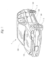
- Figure 1 is an outside view showing the arrangement of sensor units in a motor vehicle in a first embodiment of the present invention
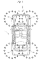
- Figure 2 is a top view showing the arrangement of sensor units in a motor vehicle in the first embodiment of the present invention
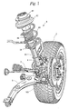
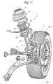
- Figure 3 is a drawing for explaining a mounted location of a sensor unit in a motor vehicle in the first embodiment of the present invention
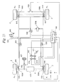
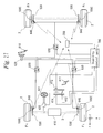
- Figure 4 is a structural diagram showing a motor vehicle drive control system in the first embodiment of the present invention.
- a drive control system of a four-wheel vehicle will be explained as an example.
- reference numeral 1 is a motor vehicle
- reference numeral 2 is a tire (wheel)
- reference numeral 100 is a sensor unit
- reference numeral 200 is a monitor unit.
- each of four sensor units 100 is located near the tire 2 in the motor vehicle body side except the tire 2 of the motor vehicle 1.
- the sensor unit 100 is fixed in a tire side of a lower arm 5, which is a member of the motor vehicle body, so that it may move in the X-, Y-, and Z-axis directions, which are mutually orthogonal, according to the motion of the tire 2. Furthermore, in this embodiment, the X-axis is set in the fore-and-aft direction of the motor vehicle 1, the Y-axis is set in the left-and-right direction of the motor vehicle 1, and the Z-axis is set in the up-and-down direction of the motor vehicle 1.
- reference numeral 2 is the tire
- reference numeral 3 is an axle
- reference numeral 4 is a hub carrier
- reference numeral 5 is the lower arm
- reference numeral 6 is a suspension system.
- the suspension system 6 comprises an upper mount section 61, a spring upper seat 62, a coil spring 63, a rubber member 64, a hydraulic damper 65, and a damper connection member 66. Furthermore, in this embodiment, a suspension system body consists of the above-mentioned spring upper seat 62, coil spring 63, rubber member 64, and hydraulic damper 65.
- a top face of the upper mount section 61 for absorbing the change of an angle of the damper 65 to the motor vehicle body is connected to a motor vehicle body (not shown), and the spring upper seat 62 is mounted on a bottom face of the upper mount section 61.
- the coil spring 63 is mounted between the spring upper seat 62 and a circular ring saucer type guide 66 provided in the cylindrical damper 65.
- the approximately cylindrical rubber member 64 is provided inside the coil spring 63.
- a lower edge of the damper 65 is fixed to the damper connection member 66, the damper connection member 66 is connected to the hub carrier 4, and the axle 3 is supported by the hub carrier 4. Furthermore, the hub carrier 4 is connected to the motor vehicle body (not shown) through the lower arm 5.
- reference numeral 2 is the tire
- reference numeral 3 is the axle
- reference numeral 100 is a sensor unit
- reference numeral 200 is a monitoring device
- reference numeral 410 is an engine
- reference numeral 411 is an accelerator pedal
- reference numeral 412 is a subthrottle actuator
- reference numeral 413 is a main throttle position sensor
- reference numeral 414 is a subthrottle position sensor
- reference numeral 421 is a steering wheel
- reference numeral 422 is a turning angle sensor
- reference numerals 510 and 520 are sensors detecting the rotating speed of a tire
- reference numeral 610 is a brake pedal
- reference numeral 620 is a master cylinder for a brake
- reference numeral 630 is a pressure control valve which controls hydraulic pressure for a brake
- reference numeral 640 is an actuator for brake drive
- reference numeral 700 is a stability control unit.
- the stability control unit 700 consists of a control circuit being provided with a widely known CPU, fetches the detection result outputted from the rotational frequency sensors 510 and 520 which detect the rotating speed of each tire 2 which is mounted in the motor vehicle 1, and the detection result outputted from the throttle position sensors 413 and 414, turning angle sensor 422, and monitoring device 200, and performs stability control.
- hydraulic pressure in a master cylinder 620 rises by stepping in a brake pedal 610 at the time of braking, this hydraulic pressure is transmitted to a brake drive actuator 640 of each tire 2 through a pressure control valve, and a braking force is applied to the rotation of each tire 2 by this.
- the above-mentioned stability control unit 700 not only keeps the stability of a motor vehicle body by electrically controlling the operation status of each pressure control valve 630 as well as electrically controlling the operation status of a subthrottle actuator 412 on the basis of detection result outputted from rotational frequency sensors 510 and 520 which detect the rotating speed of each tire 2, detection result of the turning angle sensor 422, and detection result outputted from a monitoring device 200, but also automatically performs control lest the tire 2 should lock and make a slip arise.
- the sensor unit 100 is fixed to a predetermined position of the lower arm 5 as mentioned above, detects X-, Y-, and Z-axial acceleration in four corners of the front and rear, and left and right of the motor vehicle 1 by an acceleration sensor which is provided in this sensor unit 100 and is described later, and converts the acceleration, which is detected, into a digital value. Furthermore, it generates and transmits digital information including the digital value of the acceleration of the detection result. Identification information unique to each sensor unit 100 besides the digital value of the above-mentioned acceleration is included in this digital information.
- the number of the sensor units 100 provided in each lower arm 5 is not limited to one, but may be provided two or more pieces as auxiliary and the like.
- the sensor unit 100 is fixed to the lower arm 5 in this embodiment, so long as it is a position which can detect the X-, Y-, and Z-axial acceleration in four corners of the motor vehicle 1, it may be fixed to a location other than the lower arm 5. In order to avoid the influence of the acceleration by the motion of the coil spring 63 in that case, it is more desirable to be fixed within a range which is lower than the coil spring 63 and can be regarded as a rigid body consecutive to the tire 2.
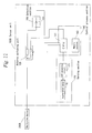
- a circuit shown in Figure 5 is cited as one embodiment of an electric system circuit of the sensor unit 100.
- the sensor unit 100 is composed of an antenna 110, an antenna switching unit 120, a rectifier circuit 130, a central process section 140, a detection section 150, a transmitting section 160, and a sensing section 170.
- the antenna 110 is for communicating using an electromagnetic wave between with the monitoring device 200, and is matched at a predetermined frequency (first frequency) in, for example, a 2.4-GHz band.
- the antenna switching unit 120 is composed of, for example, an electronic switch and the like and switches connection between the antenna 110, and rectifier circuit 130 and detection section 150, and connection between the antenna 110 and transmitting section 160 by the control of the central process section 140.
- the rectifier circuit 130 is composed of diodes 131 and 132, a capacitor 133, and a resistor 134, and forms a widely known full wave rectifier circuit.
- the antenna 110 is connected to an input side of this rectifier circuit 130 through the antenna switching unit 120.
- the rectifier circuit 130 rectifies a high frequency current induced at the antenna 110, converts it into a direct current, and outputs this as a drive power supply of the central process section 140, detection section 150, transmitting section 160, and sensing section 170.
- the central process section 140 is composed of a widely known CPU 141, digital / analog (hereafter, this is called D/A) conversion circuit 142, and memory section 143.
- D/A digital / analog
- the CPU 141 operates on the basis of a program contained in semiconductor memory of the memory section 143, generates digital information including a digital value of the acceleration detection result acquired from the sensing section 170 at the time of being driven when the electrical energy is supplied, and the identification information described later, and performs the processing of transmitting this digital information to the monitoring device 200.
- the above-mentioned identification information unique to the sensor unit 100 is stored beforehand in the memory section 143.
- the memory section 143 consists of ROM which records a program which operates the CPU 141, and, for example, nonvolatile semiconductor memory, which is electrically rewritable, such as EEPROM (electrically erasable programmable read-only memory), and the above-mentioned identification information unique to each sensor unit 100 is stored beforehand in a region, which is in the memory section 143 and is specified to be non-rewritable, at the time of production.
- nonvolatile semiconductor memory which is electrically rewritable, such as EEPROM (electrically erasable programmable read-only memory)
- EEPROM electrically erasable programmable read-only memory
- the detection section 150 consists of a diode 151 and an A/D converter 152, an anode of the diode 151 is connected to the antenna 110, and a cathode is connected to the CPU 141 of the central process section 140 through the A/D converter 152. Thereby, while an electromagnetic wave which is wave-received by the antenna 110 is detected by the detection section 150, a signal obtained by being detected is converted into a digital signal to be inputted into the CPU 141.
- the transmitting section 160 is composed of an oscillation circuit 161, a modulation circuit 162, and a high frequency amplifying circuit 163, modulates in a modulation circuit 162 a carrier wave at a 2.45-GHz-band frequency, oscillated by the oscillation circuit 161 which is composed using a widely known PLL circuit and the like, on the basis of an information signal inputted from the central process section 140, and supplies this to the antenna 110 as a high frequency current at a 2.45-GHz-band frequency (second frequency) through the high frequency amplifying circuit 163 and antenna switching unit 120.
- the above-mentioned first frequency and second frequency are set to be the same frequency in this embodiment, the first frequency may have a frequency different from the second frequency.
- the sensing section 170 is composed of an acceleration sensor 10 and an A/D conversion circuit 171.
- the acceleration sensor 10 is composed of a semiconductor acceleration sensor as shown in Figures 6 to 9.
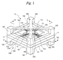
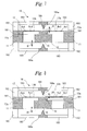
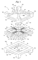
- Figure 6 is an external perspective view showing a semiconductor acceleration sensor in the first embodiment of the present invention
- Figure 7 is a sectional view taken in the direction of arrows along line B-B in Figure 6
- Figure 8 is a sectional view taken in the direction of arrows along line C-C in Figure 6
- Figure 9 is an exploded perspective view.
- reference numeral 10 denotes a semiconductor acceleration sensor, which is composed of a pedestal 11, a silicon substrate 12, and supporting members 18A and 18B.
- the pedestal 11 has a rectangular frame type form, and the silicon substrate (silicon wafer) 12 is installed on an aperture of the pedestal 11.
- an outer frame section 181 of the supporting members 18A and 18B is fixed to an outer circumferential portion of the pedestal 11.
- the silicon substrate 12 is provided on the aperture of the pedestal 11, a cross-shaped diaphragm 13 in a thin film is formed in a center section in a wafer peripheral frame section 12a, and piezo resistance elements (diffused resistor elements) Rx1 to RX4, Ry1 to Ry4, and Rz1 to Rz4 are formed on top faces of respective diaphragm blades 13a to 13d.
- piezo resistance elements diffuseused resistor elements
- the piezo,resistance elements Rx1, Rx2, Rz1, and Rz2 are formed on the diaphragm blade 13a out of the diaphragm blades 13a and 13b located on a straight line, and the piezo resistance elements Rx3, Rx4, Rz3, and Rz4 are formed on the other diaphragm blade 13b.
- the piezo resistance elements Ry1 and Ry2 are formed on the diaphragm blade 13c out of the diaphragm blades 13c and 13d located on a straight line which is orthogonal to the diaphragm blades 13a and 13b, and piezo resistance elements Ry3 and Ry4 are formed on the other diaphragm blade 13d.
- piezo resistance elements Rx1 to Rx4, Ry1 to Ry4, Rz1 to Rz4 are connected as shown in Figure 10 so as to be able to constitute resistance bridge circuits for detecting the accelerations in the X-, Y-, and Z-axis directions which are mutually orthogonal, and are connected to electrodes 191 for connection which are provided on a surface of an outer circumferential portion of the silicon substrate 12.
- a thick film section 14 is formed on an crossing section of the diaphragm blades 13a to 13d in a face side of a center section of the diaphragm 13, and a plumb bob 15 with a rectangular parallelepiped shape which consists of glass and the like is installed on a surface of this thick film section 14.
- the above-mentioned supporting members 18A and 18B are composed of an outer frame section 181 with a rectangular frame shape, four posts 182 installed in a standing manner in four corners of a fixed portion, a cross-shaped beam section 183 provided so that an end section of each post may be connected, and a conical protruding section 184 provided in a central crossing portion of the beam section 183.
- the outer frame section 181 is fit with and fixed to an outer circumferential portion of the pedestal 11 so that the protruding section 184 may be positioned in another side of the diaphragm 13, that is, in a side where the plumb bob 15 does not exist.
- setting is performed so that an end 184a of the protruding section 184 may be positioned at a distance D1 from a surface of the diaphragm 13 or plumb bob 15.
- This distance Dl is set at a value which can be restricted by the protruding section 184 lest respective diaphragm blades 13a to 13d should been extended to limits, even if acceleration arises in a direction perpendicular to the face of the diaphragm 13 and a force equal to or more than a predetermined value is applied to both face sides of the diaphragm 13 by this acceleration.
- Three resistance bridge circuits are constituted as shown in Figures 11 to 13 when using the semiconductor acceleration sensor 10 with the above-mentioned configuration.
- a positive electrode of a DC power supply 32A is connected to a node of an end of the piezo resistance element Rx1, and an end of the piezo resistance element Rx2, and a negative electrode of the DC power supply 32A is connected to a node of an end of the piezo resistance element Rx3, and an end of the piezo resistance element Rx4.
- one end of a voltage detector 31A is connected to a node of another end of the piezo resistance element Rx1, and another end of the piezo resistance element Rx4, and another end of the voltage detector 31A is connected to a node of another end of the piezo resistance element Rx2, and another end of the piezo resistance element Rx3.
- a positive electrode of a DC power supply 32B is connected to a node of an end of the piezo resistance element Ry1, and an end of the piezo resistance element Ry2, and a negative electrode of the DC power supply 32B is connected to a node of an end of the piezo resistance element Ry3, and an end of the piezo resistance element Ry4.
- one end of a voltage detector 31B is connected to a node of another end of the piezo resistance element Ry1, and another end of the piezo resistance element Ry4, and another end of the voltage detector 31B is connected to a node of another end of the piezo resistance element Ry2, and another end of the piezo resistance element Ry3.
- a positive electrode of a DC power supply 32C is connected to a node of an end of the piezo resistance element Rz1, and an end of the piezo resistance element Rz2, and a negative electrode of the DC power supply 32C is connected to a node of an end of the piezo resistance element Rz3, and an end of the piezo resistance element Rz4.
- one end of a voltage detector 31C is connected to a node of another end of the piezo resistance element Rz1, and another end of the piezo resistance element Rz3, and another end of the voltage detector 31C is connected to a node of another end of the piezo resistance element Rz2, and another end of the piezoresistance element Rz4.
- the semiconductor acceleration sensor 10 when a force generated in connection with the acceleration applied to the sensor 10 is applied to the plumb bob 15, strain arises in respective diaphragm blades 13a to 13d, and the resistance of the piezo resistance elements Rx1 to Rx4, Ry1 to Ry4, Rz1 to Rz4 varies with these. Therefore, the accelerations in the X-, Y-, and Z-axis directions which are mutually orthogonal are detectable by forming resistance bridge circuits with the piezo resistance elements Rx1 to Rx4, Ry1 to Ry4, Rz1 to Rz4 provided in respective diaphragm blades 13a to 13d.
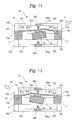
- the diaphragm 13 is distorted and extended in the direction where forces 41 and 42 act when the forces equal to or more than a predetermined value are applied to the other face sides of the diaphragm 13 when such acceleration that the forces 41 and 42 including a force component in a direction perpendicular to a face of the diaphragm 13 act is applied as shown in Figures 14 and 15, its displacement is supported and is restricted by an apex 184a of the protruding section 184, and hence, respective diaphragm blades 13a to 13d are not extended to the maximum extent.
- the semiconductor acceleration sensor 10 it is possible to detect accelerations in the X-, Y-, and Z-axis directions, which are generated in four corners of a motor vehicle and are orthogonal mutually, when the motor vehicle is traveling, as shown in Figure 2. In addition, it is also possible to estimate the grip of the tire 2 from the acceleration in the Z-axis direction.
- an A/D conversion circuit 171 converts into a digital signal an analog electric signal, outputted from the acceleration sensor 10, and outputs it to the CPU 141.
- This digital signal corresponds to values of the accelerations in the above-mentioned X-, Y-, and Z-axis directions.
- acceleration in a positive direction and acceleration in a negative direction exist as accelerations generated in respective X-, Y-, and Z-axis directions, it is possible in this embodiment to detect both accelerations.
- this embodiment it is made hard to be influenced by metal by using the 2.45-GHz-band frequency as the above-mentioned first and second frequencies as mentioned above. In this way, in order to make it hard to be influenced by metal, it is preferable to use a 1-GHz or more frequency as the above-mentioned first and second frequencies.
- the monitoring device 200 is connected to the stability control unit 700 with a cable, and operates with the electrical energy sent from the stability control unit 700.
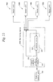
- An electric system circuit of the monitoring device 200 is composed of a radiation unit 210, a wave-receiving unit 220, a control section 230, and an arithmetic section 240 as shown in Figure 16.
- the control section 230 and arithmetic section 240 are composed of a widely known CPU, and a memory circuit composed of ROM where a program which operates this CPU is stored, RAM necessary for performing data processing, and the like.
- the radiation unit 210 is composed of an antenna 211 and a transmitting section 212 for radiating an electromagnetic wave at a 2.45-GHz-band predetermined frequency (the above-mentioned first frequency), and radiates the electromagnetic wave at the above-mentioned first frequency from the antenna 211 on the basis of an instruction from the control section 230.
- the transmitting section 212 similarly to the transmitting section 160 of the sensor unit 100, it is possible to cite the circuit which is composed of an oscillation circuit 161, a modulation circuit 162, and a high frequency amplifying circuit 163. Thereby, the 2.45-GHz electromagnetic wave is radiated from the antenna 211. Furthermore, high-frequency power outputted from the transmitting section 212 is set at a value of such extent that electrical energy can be supplied from the antenna 211 for electromagnetic wave radiation of the monitoring device 200 to the sensor unit 100.
- the wave-receiving unit 220 is composed of an antenna 221 and a detection section 222 for wave-receiving an electromagnetic wave at a 2.45-GHz-band predetermined frequency (the above-mentioned second frequency), detects the electromagnetic wave at the above-mentioned second frequency which is wave-received by the antenna 221 on the basis of an instruction from the control section 230, and converts a signal, which is detected and obtained, into a digital signal to output it to the arithmetic section 250.
- the detection section 222 the same circuit as the detection section 150 of the sensor unit 100 is cited.
- the control section 230 drives the transmitting section 212 to make an electromagnetic wave radiated only during predetermined time t3, and then, drives the detection section 222 during predetermined time t4 to make the detection section 222 output a digital signal to the arithmetic section 240.
- the arithmetic section 240 calculates the above-mentioned acceleration on the basis of this digital signal, and outputs it to the stability control unit 700. Then, the control section 230 repeats the same processing as the above-mentioned.
- the above-mentioned radiation time t3 in the monitoring device 200 is set at 0.15 ms, and the above-mentioned wave-receiving time t4 is at 0.30 ms, respectively.
- the above-mentioned wave-receiving time t4 is at 0.30 ms, respectively.
- Distortion characteristic information expressing the relationship between the accelerations in the above-mentioned X-, Y-, and Z-axis directions and the distortion amount of the tire 2 which is obtained from the monitoring device 200 is acquired beforehand by the measurement such as an experiment and is stored in the stability control unit 700. Furthermore, the stability control unit 700 estimates the distortion amount of each tire 2 on the basis of the detection result on acceleration and the distortion characteristic information, controls the pressure control valve 630 as well as driving the subthrottle actuator 412 on the basis of this estimated distortion amount of the tire 2, and drives the brake drive actuator 640.
- the motor vehicle drive control system mentioned above it is possible to detect the accelerations in the X-, Y-, and Z-axis directions, which are generated in four corners of a motor vehicle respectively and which are orthogonal mutually, when the motor vehicle is traveling, furthermore, it is possible to estimate the distortion amount of the tire 2, a sideslip state of a motor vehicle body, an idling state of the tire 2, and the like which are generated at the time of the motor vehicle traveling since it is possible to estimate the grip and lift of the tire 2 from the acceleration in the Z-axis direction, and it is possible to control the above-mentioned respective actuators so that stable traveling can be performed on the basis of these.
- the sensor unit 100 is mounted on a motor vehicle body instead of the tire 2, it is possible to perform highly accurate control even if the tire 2 is replaced to a tire, whose type differs, and a frictional force between the tire 2 and a road surface changes. Furthermore, even if it is a motor vehicle which makes drive control according to each of the tires 2 such as a 4WD vehicle, it is possible to perform highly accurate control.
- the sensor unit 100 transmits detection result when wave-receiving an electromagnetic wave radiated from the monitoring device 200 and obtains electrical energy, it is possible to obtain the above-mentioned effects even if the detection section 150 is not provided.
- the sensor unit 100 is provided with the detection section 150, by setting a program and the like so that the sensor unit 100 may transmit detection result when receiving self identification information from the monitoring device 200, it never arises to transmit the detection result by unnecessary noise from the outside, and thereby, it is possible to prevent an unnecessary electromagnetic wave from being radiated.
- both of the above-mentioned first and second frequencies are set at 2.45 GHZ in this embodiment, it is not limited to this, but it is possible to obtain detection data by the sensor unit 100 in high precision by extremely decreasing the influence of reflection, cutoff, and the like of an electromagnetic wave by tires and metal of a motor vehicle body so long as it is 1 GHz or more of frequency as mentioned above, and hence, there arises no problem even if these first and second frequencies are different frequencies. It is preferable to suitably set these first and second frequencies at the time of a design.
- the object of the present invention to detect accelerations in the X-, Y-, and Z-axis directions which are generated in each of four corners of the motor vehicle 1 and which are orthogonal mutually, it is possible to control each actuator even if a part or all of respective sensor units 100 are provided in locations other than four corners of a motor vehicle, needless to say, even if the number of the sensor units is not less than four, or even if it is less than four.
- Figure 17 is an outside view showing the arrangement of sensor units in a motor vehicle in a second embodiment of the present invention
- Figure 18 is a top view showing the arrangement of sensor units in a motor vehicle in the second embodiment of the present invention
- Figure 19 is a structural diagram showing a motor vehicle drive control system in the second embodiment of the present invention
- Figure 20 is a drawing for explaining communication among a monitoring device and sensor units in the second embodiment of the present invention.
- the same components as those of the first embodiment mentioned above are expressed with the same reference numerals, and their explanation will be omitted.
- difference between the second embodiment and first embodiment is that, in the second embodiment, the sensor unit 100A is provided also in a center section of the motor vehicle 1, and the stability control unit 700 controls each actuator also in consideration of the acceleration detected by the sensor unit 100A.
- the sensor unit 100A has the same configuration as the sensor unit 100 of the first embodiment, and as shown in Figure 18, it is located behind the central point FP of the motor vehicle 1 by the distance Ll. Thus, it is possible to detect the change of the center position of the motor vehicle 1 in high accuracy by providing the sensor unit 100A in a position shifted from the central point FP. Furthermore, it is preferable to set the distance L1 suitably according to a type of a motor vehicle.
- each actuator is given drive control by the stability control unit 700 in consideration of the acceleration detected by the sensor unit 100 A located in the center section of a motor vehicle by one monitoring device 200, it is possible to perform further highly accurate control, and hence, it is possible to further increase stability at the time of motor vehicle traveling.
- Figure 21 is a structural diagram showing a motor vehicle drive control system in a third embodiment of the present invention
- Figure 22 is a structural diagram showing an electric system circuit of a sensor unit in the third embodiment of the present invention
- Figure 23 is a drawing for explaining communication among a monitoring device and sensor units in the third embodiment of the present invention.
- the same components as those of the first embodiment mentioned above are expressed with the same reference numerals, and their explanation will be omitted.
- difference between the third embodiment and first embodiment is that, in the third embodiment, the monitoring device 200B and each sensor unit 100B are connected with a cable, and the supply of electrical energy and the transmission of digital information including detection result is performed using the cable.
- the sensor unit 100B operates not from a high frequency current induced at an antenna, but by electrical energy sent through the cable from the monitoring device 200B, the antenna and a rectifier circuit become unnecessary.
- digital information is transmitted not through,an electromagnetic wave, which is radiated from an antenna, but through the cable, not only a transmitting section becomes unnecessary, but also a D/A conversion circuit becomes unnecessary since the digital information which the CPU 141 generates is transmitted as it is.
- the monitoring device 200B is connected to each sensor unit 100B through a cable. Furthermore, although electrical energy is sent to each sensor unit 100B from the monitoring device 200B in this embodiment, this is not limited to the monitoring device 200B, but it is also sufficient to be another apparatus which is connected through a cable.
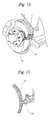
- Figure 24 is a drawing for explaining a mounted state of a sensor unit in a fourth embodiment of the present invention
- Figure 25 is a drawing for explaining another mounted state of a sensor unit in the fourth embodiment of the present invention
- Figure 26 is a drawing for explaining X-, Y-, and Z-axial accelerations, which are detected by sensor units, in the fourth embodiment of the present invention
- Figure 27 is a structural diagram showing a motor vehicle drive control system in the fourth embodiment of the present invention.
- each sensor unit 100C in order to mount a wheel, is provided in a body of rotation which is provided in a motor vehicle body side, and the stability control unit 700 controls each actuator by acceleration detected by the sensor unit 100C.
- the sensor unit 100C has the same configuration as the sensor unit 100 of the first embodiment, and is fixed to a predetermined position of the brake disc 530 which rotates with the tire 2.
- the sensor unit 100C is fixed to the brake disc 530 in this embodiment, this is not limited to this, but it is also sufficient to fix it to the axle 3, a rotor (not shown), or the like so long as it is a body of rotation.
- a rotor (not shown), or the like so long as it is a body of rotation.
- the tire 2 is, for example, a widely known tubeless radial tire, which is composed of a tire body 305, the rim 306, and a wheel (not shown), and the tire body 305 is composed of a widely known cap tread 301, an undertread 302, belts 303A and 303B, a carcass 304, and the like.
- the sensor unit 100C is provided as shown in Figure 26 so that the X-axis may correspond to a rotary direction of the tire 2, the Y-axis may correspond to a direction of a rotating shaft, and the Z-axis may correspond to a direction orthogonal to the rotating shaft, it is possible to detect the accelerations in the X-, Y-, and Z-axis directions, which are generated in connection with the rotation of the tire 2 and which are orthogonal mutually, when the tire 2 is rotating and a motor vehicle is traveling.
- a rotating speed sensor since it is possible to find the rotating speed of a wheel from the acceleration in an X-axis direction as described later, a rotating speed sensor becomes unnecessary by calculating the rotating speed of a wheel per unit time in the sensor unit 100C, and transmitting it with including it in digital information.
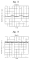
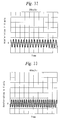
- Figures 28 to 30 show measured result of acceleration in a Z-axis direction
- Figures 31 to 33 show measured result of acceleration in an X-axis direction
- Figures 34 to 35 show measured result of acceleration in a Y-axis direction
- Figure 36 shows measured result of acceleration in an X-axis direction when applying brakes
- Figure 37 shows actually measured result of acceleration in a Z-axis direction when applying the brakes, respectively.
- Figure 28 shows actual measurements of acceleration in the Z-axis direction at the time of traveling at 2.5 km/h
- Figure 29 shows actual measurements of acceleration in the Z-axis direction at the time of traveling at 20 km/h
- Figure 30 shows actual measurements of acceleration in the Z-axis direction at the time of traveling at 40 km/h.
- Figure 31 shows actual measurements of acceleration in the X-axis direction at the time of traveling at 2.5 km/h
- Figure 32 shows actual measurements of acceleration in the X-axis direction at the time of traveling at 20 km/h
- Figure 33 shows actual measurements of acceleration in the X-axis direction at the time of traveling at 40 km/h.
- Figure 34 shows actual measurements of acceleration in the Y-axis direction when turning a wheel to the right at the time of traveling
- Figure 35 shows actual measurements of acceleration in the Y-axis direction when turning a wheel to the left at the time of traveling.
- the acceleration in the Y-axis direction appears remarkably.
- the acceleration in a reverse direction arises because a driver turns a little a steering wheel in a reverse direction unconsciously.
- the sensor unit 100C is mounted on a body of rotation provided in a motor vehicle body for mounting a wheel not on a wheel, it is possible to perform highly accurate control even if the type of the tire 2 which is mounted in a wheel is different, and a frictional force between the tire 2 and a road surface changes. Furthermore, even if it is a motor vehicle which makes separately drive control according to each of the tires 2 such as a 4WD vehicle, it is possible to perform highly accurate control.
- the present invention is not limited to only the above-mentioned embodiments, but it is also acceptable to perform various kinds of modification within the scope of the present invention.
Landscapes
- Engineering & Computer Science (AREA)
- Mechanical Engineering (AREA)
- Transportation (AREA)
- Combustion & Propulsion (AREA)
- Chemical & Material Sciences (AREA)
- General Physics & Mathematics (AREA)
- Physics & Mathematics (AREA)
- Automation & Control Theory (AREA)
- Regulating Braking Force (AREA)
- Electric Propulsion And Braking For Vehicles (AREA)
- Control Of Driving Devices And Active Controlling Of Vehicle (AREA)
- Control Of Vehicle Engines Or Engines For Specific Uses (AREA)
- Electrical Control Of Air Or Fuel Supplied To Internal-Combustion Engine (AREA)
- Arrangements For Transmission Of Measured Signals (AREA)
- Auxiliary Drives, Propulsion Controls, And Safety Devices (AREA)
Applications Claiming Priority (3)
| Application Number | Priority Date | Filing Date | Title |
|---|---|---|---|
| JP2003182537 | 2003-06-26 | ||
| JP2004057370A JP2005035523A (ja) | 2003-06-26 | 2004-03-02 | 車両駆動制御システム及びそのセンサユニット |
| PCT/JP2004/008737 WO2005000652A1 (fr) | 2003-06-26 | 2004-06-22 | Systeme de commande d'entrainement d'un vehicule automobile et unite formant capteur associee |
Publications (3)
| Publication Number | Publication Date |
|---|---|
| EP1642794A1 true EP1642794A1 (fr) | 2006-04-05 |
| EP1642794A4 EP1642794A4 (fr) | 2010-08-04 |
| EP1642794B1 EP1642794B1 (fr) | 2015-03-11 |
Family
ID=33554453
Family Applications (1)
| Application Number | Title | Priority Date | Filing Date |
|---|---|---|---|
| EP04746206.4A Expired - Lifetime EP1642794B1 (fr) | 2003-06-26 | 2004-06-22 | Systeme de commande d'entrainement d'un vehicule automobile et unite formant capteur associee |
Country Status (4)
| Country | Link |
|---|---|
| US (1) | US8055423B2 (fr) |
| EP (1) | EP1642794B1 (fr) |
| JP (1) | JP2005035523A (fr) |
| WO (1) | WO2005000652A1 (fr) |
Cited By (4)
| Publication number | Priority date | Publication date | Assignee | Title |
|---|---|---|---|---|
| DE102006040676B3 (de) * | 2006-08-30 | 2008-03-27 | Ab Skf | Straßenfahrzeug, nämlich Personenkraftwagen oder Lastkraftwagen |
| CN101468592A (zh) * | 2007-12-27 | 2009-07-01 | 光阳工业股份有限公司 | 电动全地形车控制构造 |
| EP1816048A4 (fr) * | 2004-11-05 | 2009-11-18 | Yokohama Rubber Co Ltd | Procédé pour déterminer le motif de contact entre le sol et le pneu et son dispositif |
| EP2036746A3 (fr) * | 2007-09-17 | 2012-12-12 | S & T Daewoo Co., Ltd. | Module capteur comprenant un capteur d'accélération et un capteur de déplacement relatif, amortisseur et système de suspension électroniquement contrôlable le comprenant, et procédé pour le contrôle du mouvement du véhicule l'utilisant |
Families Citing this family (6)
| Publication number | Priority date | Publication date | Assignee | Title |
|---|---|---|---|---|
| JP2006142993A (ja) * | 2004-11-19 | 2006-06-08 | Yokohama Rubber Co Ltd:The | 加速度センサ装着タイヤ |
| JP2009035081A (ja) * | 2007-07-31 | 2009-02-19 | Equos Research Co Ltd | 制御装置 |
| JP5086385B2 (ja) * | 2010-03-08 | 2012-11-28 | 日立オートモティブシステムズ株式会社 | 電動パワーステアリング制御装置 |
| US8712599B1 (en) * | 2013-02-22 | 2014-04-29 | Analog Devices Technology | Vehicle inertial sensor systems |
| JP6915507B2 (ja) * | 2017-11-23 | 2021-08-04 | 株式会社デンソー | 路面状態判別装置 |
| CN115217176B (zh) * | 2022-07-06 | 2023-06-13 | 三一重机有限公司 | 电磁制动器的控制方法、装置及电动作业机械 |
Family Cites Families (38)
| Publication number | Priority date | Publication date | Assignee | Title |
|---|---|---|---|---|
| JPS52109981A (en) | 1976-03-11 | 1977-09-14 | Nippon Signal Co Ltd:The | Code recognition system in a speed detector |
| DE3703630A1 (de) * | 1987-02-06 | 1988-08-18 | Bosch Gmbh Robert | Beschleunigungsaufnehmer |
| JP2586497B2 (ja) * | 1987-07-07 | 1997-02-26 | トヨタ自動車株式会社 | 車両のロ−リング抑制装置 |
| IT1223919B (it) * | 1988-11-18 | 1990-09-29 | Leonardo Fioravanti | Procedimento e sistema per la rilevazione delle impronte di appoggio dei pneumatici di un autoveicolo particolarmente per l'ottimizzazione automatica del comportamento del l'autoveicolo |
| EP0461265B1 (fr) * | 1989-12-28 | 1995-05-10 | Wacoh Corporation | Capteurs d'accélération |
| US6864677B1 (en) * | 1993-12-15 | 2005-03-08 | Kazuhiro Okada | Method of testing a sensor |
| DE4201146C2 (de) * | 1991-01-18 | 2003-01-30 | Hitachi Ltd | Vorrichtung zur Steuerung des Kraftfahrzeugverhaltens |
| JPH06258195A (ja) | 1991-08-19 | 1994-09-16 | Kyowa Seisakusho:Kk | サイドスリップテスター |
| JPH05338528A (ja) | 1992-06-09 | 1993-12-21 | Mazda Motor Corp | 自動車のブレーキ装置 |
| JP3022038B2 (ja) * | 1993-03-04 | 2000-03-15 | トヨタ自動車株式会社 | 路面摩擦係数検出装置 |
| JP3435729B2 (ja) | 1993-05-21 | 2003-08-11 | 株式会社日立製作所 | 車両の能動消音装置 |
| US5678144A (en) * | 1994-10-11 | 1997-10-14 | Konica Corporation | Image forming apparatus having a rotational information detector for a photoreceptor |
| EP0788955B1 (fr) * | 1995-09-19 | 2003-11-26 | Japan Electronics Industry, Ltd. | Méthode de commande pour des systèmes d'antiblocage |
| DE69836301T2 (de) * | 1997-07-29 | 2007-06-06 | Toyota Jidosha Kabushiki Kaisha, Toyota | Elektrisch betätigte Bremsanlage mit Betätigungsvorrichtung eines elektrischen Bremsmotors zur Erlangung einer Beziehung zwischen Motorkraft und Bremsmoment |
| JPH1194018A (ja) * | 1997-09-25 | 1999-04-09 | Toyota Motor Corp | 運輸装置用ダイナミックダンパ |
| DE19807004A1 (de) * | 1998-02-19 | 1999-09-09 | Siemens Ag | Sensorsystem und Verfahren für Überwachung/Messung des Kraftschlusses eines Fahrzeugreifens mit der Fahrbahn und weiterer physikalischer Daten des Reifens |
| JP3330074B2 (ja) * | 1998-02-24 | 2002-09-30 | 松下電工株式会社 | 3軸加速度センサ |
| JP4184536B2 (ja) * | 1999-04-26 | 2008-11-19 | 横浜ゴム株式会社 | トランスポンダ素子及びトランスポンダ |
| JP2001018775A (ja) | 1999-07-05 | 2001-01-23 | Unisia Jecs Corp | ブレーキ制御装置 |
| US6204758B1 (en) * | 1999-07-23 | 2001-03-20 | Schrader-Bridgeport International, Inc. | System to automatically determine wheel position for automotive remote tire monitoring system |
| DE19954807A1 (de) | 1999-11-13 | 2001-05-17 | Bosch Gmbh Robert | Verfahren und Vorrichtung zur Steuerung eines Fahrzeugs |
| US6278361B1 (en) * | 1999-12-03 | 2001-08-21 | Trw Inc. | System and method for monitoring vehicle conditions affecting tires |
| JP4474768B2 (ja) | 2000-11-28 | 2010-06-09 | 株式会社デンソー | ブレーキ装置 |
| JP4779246B2 (ja) * | 2001-06-28 | 2011-09-28 | トヨタ自動車株式会社 | タイヤ作用力検出装置 |
| US6759952B2 (en) * | 2001-07-06 | 2004-07-06 | Trw Inc. | Tire and suspension warning and monitoring system |
| JP4114044B2 (ja) | 2001-07-17 | 2008-07-09 | トヨタ自動車株式会社 | タイヤ作用力検出装置 |
| JP3562501B2 (ja) | 2001-08-16 | 2004-09-08 | トヨタ自動車株式会社 | 車両運動制御装置 |
| JP2003341500A (ja) * | 2002-05-24 | 2003-12-03 | Aisin Seiki Co Ltd | アンチスキッド制御装置 |
| WO2004045933A2 (fr) * | 2002-11-18 | 2004-06-03 | Nsk Ltd. | Unite d'essieu munie d'un capteur de patinage et procede de mesure de patinage |
| JP2005029142A (ja) * | 2003-06-17 | 2005-02-03 | Yokohama Rubber Co Ltd:The | アンチロック・ブレーキ・システム及びそのセンサユニット |
| JP4213545B2 (ja) * | 2003-09-05 | 2009-01-21 | 株式会社ジェイテクト | 車輪のグリップ度推定装置、及び該装置を備えた車両の運動制御装置 |
| US7367227B2 (en) * | 2004-01-20 | 2008-05-06 | Schrader Bridgeport International | Determination of wheel sensor position using shock sensors and a wireless solution |
| JP3752251B2 (ja) * | 2004-07-01 | 2006-03-08 | シャープ株式会社 | 自走式移動車 |
| US7991532B2 (en) * | 2004-12-27 | 2011-08-02 | Equos Research Co., Ltd. | Wheel control device and control device |
| WO2006095429A1 (fr) * | 2005-03-10 | 2006-09-14 | The Yokohama Rubber Co., Ltd. | Systeme de detection de l'etat d'une surface de route, systeme de suspension active, systeme de freinage antiblocage et capteur pour le systeme de detection de l'etat d'une surface de route |
| US20080065305A1 (en) * | 2005-03-11 | 2008-03-13 | Yutaka Hattori | Traction Control System and Sensor Unit Thereof |
| DE102007003255A1 (de) * | 2006-01-24 | 2007-09-06 | The Yokohama Rubber Co., Ltd., Hiratsuka | Vorrichtung und Verfahren zum Vorhersagen eines Bremswegs eines Fahrzeugs |
| WO2009005073A1 (fr) * | 2007-07-02 | 2009-01-08 | Equos Research Co., Ltd. | Dispositif de commande d'angle de carrossage |
-
2004
- 2004-03-02 JP JP2004057370A patent/JP2005035523A/ja active Pending
- 2004-06-22 EP EP04746206.4A patent/EP1642794B1/fr not_active Expired - Lifetime
- 2004-06-22 WO PCT/JP2004/008737 patent/WO2005000652A1/fr not_active Ceased
- 2004-06-22 US US10/561,738 patent/US8055423B2/en not_active Expired - Fee Related
Cited By (4)
| Publication number | Priority date | Publication date | Assignee | Title |
|---|---|---|---|---|
| EP1816048A4 (fr) * | 2004-11-05 | 2009-11-18 | Yokohama Rubber Co Ltd | Procédé pour déterminer le motif de contact entre le sol et le pneu et son dispositif |
| DE102006040676B3 (de) * | 2006-08-30 | 2008-03-27 | Ab Skf | Straßenfahrzeug, nämlich Personenkraftwagen oder Lastkraftwagen |
| EP2036746A3 (fr) * | 2007-09-17 | 2012-12-12 | S & T Daewoo Co., Ltd. | Module capteur comprenant un capteur d'accélération et un capteur de déplacement relatif, amortisseur et système de suspension électroniquement contrôlable le comprenant, et procédé pour le contrôle du mouvement du véhicule l'utilisant |
| CN101468592A (zh) * | 2007-12-27 | 2009-07-01 | 光阳工业股份有限公司 | 电动全地形车控制构造 |
Also Published As
| Publication number | Publication date |
|---|---|
| JP2005035523A (ja) | 2005-02-10 |
| EP1642794A4 (fr) | 2010-08-04 |
| US8055423B2 (en) | 2011-11-08 |
| EP1642794B1 (fr) | 2015-03-11 |
| WO2005000652A1 (fr) | 2005-01-06 |
| US20080195279A1 (en) | 2008-08-14 |
Similar Documents
| Publication | Publication Date | Title |
|---|---|---|
| EP1816013A1 (fr) | Pneu equipe d un capteur d acceleration | |
| EP1857325A1 (fr) | Systeme de detection de l'etat d'une surface de route, systeme de suspension active, systeme de freinage antiblocage et capteur pour le systeme de detection de l'etat d'une surface de route | |
| US7792617B2 (en) | Wheel speed sensing system for electronic stability control | |
| EP1642794B1 (fr) | Systeme de commande d'entrainement d'un vehicule automobile et unite formant capteur associee | |
| EP1669222B1 (fr) | Procédé et dispositif de détermination de l'état de déplacement d'un véhicule | |
| CN101509936A (zh) | 用于校准车轮速度的方法 | |
| EP1634788B1 (fr) | Systeme de freinage antiblocage et unite de detection associee a ce systeme | |
| US7970510B2 (en) | Vehicle drive control system and sensor unit and tire | |
| JP4170994B2 (ja) | タイヤ接地パターン特定方法及びその装置 | |
| KR20060130255A (ko) | 트랙션 컨트롤 시스템 및 그 센서 유닛 | |
| EP1795902A1 (fr) | Procede et dispositif de detection de l acceleration, module capteur d acceleration et pneumatique | |
| KR20070120524A (ko) | 노면 상태 검출 시스템, 액티브 서스펜션 시스템,안티-로크 브레이크 시스템, 및 노면 상태 검출 시스템용센서 유닛 | |
| JP2005247068A (ja) | 路面状態検出システム及びアクティブ・サスペンション・システム及びアンチロック・ブレーキ・システム並びにそのセンサユニット | |
| CN117584981A (zh) | 用于估计摩擦势系数的方法和估计装置 | |
| US20050110626A1 (en) | System and method for determining at least one parameter of at least one rotating member by means of reference and speed signals | |
| JP4543376B2 (ja) | 電力供給システム | |
| KR100358486B1 (ko) | 차륜의 에어갭 진단방법 | |
| JP2006321298A (ja) | 車両駆動制御システム | |
| JP5251223B2 (ja) | 電気自動車の制御装置 | |
| JPH08184610A (ja) | 加速度センサの異常検出方法 | |
| JPH0585321A (ja) | 車両走行状態演算装置 |
Legal Events
| Date | Code | Title | Description |
|---|---|---|---|
| PUAI | Public reference made under article 153(3) epc to a published international application that has entered the european phase |
Free format text: ORIGINAL CODE: 0009012 |
|
| 17P | Request for examination filed |
Effective date: 20060119 |
|
| AK | Designated contracting states |
Kind code of ref document: A1 Designated state(s): DE GB IT |
|
| DAX | Request for extension of the european patent (deleted) | ||
| RBV | Designated contracting states (corrected) |
Designated state(s): DE GB IT |
|
| A4 | Supplementary search report drawn up and despatched |
Effective date: 20100702 |
|
| 17Q | First examination report despatched |
Effective date: 20100917 |
|
| GRAP | Despatch of communication of intention to grant a patent |
Free format text: ORIGINAL CODE: EPIDOSNIGR1 |
|
| INTG | Intention to grant announced |
Effective date: 20141023 |
|
| GRAS | Grant fee paid |
Free format text: ORIGINAL CODE: EPIDOSNIGR3 |
|
| GRAA | (expected) grant |
Free format text: ORIGINAL CODE: 0009210 |
|
| AK | Designated contracting states |
Kind code of ref document: B1 Designated state(s): DE GB IT |
|
| REG | Reference to a national code |
Ref country code: GB Ref legal event code: FG4D |
|
| REG | Reference to a national code |
Ref country code: DE Ref legal event code: R096 Ref document number: 602004046781 Country of ref document: DE Effective date: 20150423 |
|
| REG | Reference to a national code |
Ref country code: DE Ref legal event code: R097 Ref document number: 602004046781 Country of ref document: DE |
|
| PG25 | Lapsed in a contracting state [announced via postgrant information from national office to epo] |
Ref country code: IT Free format text: LAPSE BECAUSE OF FAILURE TO SUBMIT A TRANSLATION OF THE DESCRIPTION OR TO PAY THE FEE WITHIN THE PRESCRIBED TIME-LIMIT Effective date: 20150311 |
|
| REG | Reference to a national code |
Ref country code: DE Ref legal event code: R119 Ref document number: 602004046781 Country of ref document: DE |
|
| PLBE | No opposition filed within time limit |
Free format text: ORIGINAL CODE: 0009261 |
|
| STAA | Information on the status of an ep patent application or granted ep patent |
Free format text: STATUS: NO OPPOSITION FILED WITHIN TIME LIMIT |
|
| 26N | No opposition filed |
Effective date: 20151214 |
|
| GBPC | Gb: european patent ceased through non-payment of renewal fee |
Effective date: 20150622 |
|
| PG25 | Lapsed in a contracting state [announced via postgrant information from national office to epo] |
Ref country code: DE Free format text: LAPSE BECAUSE OF NON-PAYMENT OF DUE FEES Effective date: 20160101 Ref country code: GB Free format text: LAPSE BECAUSE OF NON-PAYMENT OF DUE FEES Effective date: 20150622 |