EP1643163A2 - Dispositif et méthode de compensation de performance de rechauffage d'une tranmsission à variation continue - Google Patents
Dispositif et méthode de compensation de performance de rechauffage d'une tranmsission à variation continue Download PDFInfo
- Publication number
- EP1643163A2 EP1643163A2 EP05020464A EP05020464A EP1643163A2 EP 1643163 A2 EP1643163 A2 EP 1643163A2 EP 05020464 A EP05020464 A EP 05020464A EP 05020464 A EP05020464 A EP 05020464A EP 1643163 A2 EP1643163 A2 EP 1643163A2
- Authority
- EP
- European Patent Office
- Prior art keywords
- vehicle
- heating
- speed range
- performance
- cvt
- Prior art date
- Legal status (The legal status is an assumption and is not a legal conclusion. Google has not performed a legal analysis and makes no representation as to the accuracy of the status listed.)
- Granted
Links
Images



Classifications
-
- F—MECHANICAL ENGINEERING; LIGHTING; HEATING; WEAPONS; BLASTING
- F16—ENGINEERING ELEMENTS AND UNITS; GENERAL MEASURES FOR PRODUCING AND MAINTAINING EFFECTIVE FUNCTIONING OF MACHINES OR INSTALLATIONS; THERMAL INSULATION IN GENERAL
- F16H—GEARING
- F16H61/00—Control functions within control units of change-speed- or reversing-gearings for conveying rotary motion ; Control of exclusively fluid gearing, friction gearing, gearings with endless flexible members or other particular types of gearing
- F16H61/66—Control functions within control units of change-speed- or reversing-gearings for conveying rotary motion ; Control of exclusively fluid gearing, friction gearing, gearings with endless flexible members or other particular types of gearing specially adapted for continuously variable gearings
- F16H61/662—Control functions within control units of change-speed- or reversing-gearings for conveying rotary motion ; Control of exclusively fluid gearing, friction gearing, gearings with endless flexible members or other particular types of gearing specially adapted for continuously variable gearings with endless flexible members
- F16H61/66254—Control functions within control units of change-speed- or reversing-gearings for conveying rotary motion ; Control of exclusively fluid gearing, friction gearing, gearings with endless flexible members or other particular types of gearing specially adapted for continuously variable gearings with endless flexible members controlling of shifting being influenced by a signal derived from the engine and the main coupling
- F16H61/66259—Control functions within control units of change-speed- or reversing-gearings for conveying rotary motion ; Control of exclusively fluid gearing, friction gearing, gearings with endless flexible members or other particular types of gearing specially adapted for continuously variable gearings with endless flexible members controlling of shifting being influenced by a signal derived from the engine and the main coupling using electrical or electronical sensing or control means
-
- B—PERFORMING OPERATIONS; TRANSPORTING
- B60—VEHICLES IN GENERAL
- B60H—ARRANGEMENTS OF HEATING, COOLING, VENTILATING OR OTHER AIR-TREATING DEVICES SPECIALLY ADAPTED FOR PASSENGER OR GOODS SPACES OF VEHICLES
- B60H1/00—Heating, cooling or ventilating devices
- B60H1/00314—Arrangements permitting a rapid heating of the heating liquid
-
- B—PERFORMING OPERATIONS; TRANSPORTING
- B60—VEHICLES IN GENERAL
- B60W—CONJOINT CONTROL OF VEHICLE SUB-UNITS OF DIFFERENT TYPE OR DIFFERENT FUNCTION; CONTROL SYSTEMS SPECIALLY ADAPTED FOR HYBRID VEHICLES; ROAD VEHICLE DRIVE CONTROL SYSTEMS FOR PURPOSES NOT RELATED TO THE CONTROL OF A PARTICULAR SUB-UNIT
- B60W30/00—Purposes of road vehicle drive control systems not related to the control of a particular sub-unit, e.g. of systems using conjoint control of vehicle sub-units
- B60W30/18—Propelling the vehicle
- B60W30/192—Mitigating problems related to power-up or power-down of the driveline, e.g. start-up of a cold engine
- B60W30/194—Mitigating problems related to power-up or power-down of the driveline, e.g. start-up of a cold engine related to low temperature conditions, e.g. high viscosity of hydraulic fluid
-
- F—MECHANICAL ENGINEERING; LIGHTING; HEATING; WEAPONS; BLASTING
- F16—ENGINEERING ELEMENTS AND UNITS; GENERAL MEASURES FOR PRODUCING AND MAINTAINING EFFECTIVE FUNCTIONING OF MACHINES OR INSTALLATIONS; THERMAL INSULATION IN GENERAL
- F16H—GEARING
- F16H57/00—General details of gearing
- F16H57/04—Features relating to lubrication or cooling or heating
- F16H57/0412—Cooling or heating; Control of temperature
- F16H57/0413—Controlled cooling or heating of lubricant; Temperature control therefor
-
- F—MECHANICAL ENGINEERING; LIGHTING; HEATING; WEAPONS; BLASTING
- F16—ENGINEERING ELEMENTS AND UNITS; GENERAL MEASURES FOR PRODUCING AND MAINTAINING EFFECTIVE FUNCTIONING OF MACHINES OR INSTALLATIONS; THERMAL INSULATION IN GENERAL
- F16H—GEARING
- F16H57/00—General details of gearing
- F16H57/04—Features relating to lubrication or cooling or heating
- F16H57/048—Type of gearings to be lubricated, cooled or heated
- F16H57/0487—Friction gearings
- F16H57/0489—Friction gearings with endless flexible members, e.g. belt CVTs
-
- B—PERFORMING OPERATIONS; TRANSPORTING
- B60—VEHICLES IN GENERAL
- B60Y—INDEXING SCHEME RELATING TO ASPECTS CROSS-CUTTING VEHICLE TECHNOLOGY
- B60Y2300/00—Purposes or special features of road vehicle drive control systems
- B60Y2300/47—Engine emissions
- B60Y2300/476—Regeneration of particle filters
-
- F—MECHANICAL ENGINEERING; LIGHTING; HEATING; WEAPONS; BLASTING
- F16—ENGINEERING ELEMENTS AND UNITS; GENERAL MEASURES FOR PRODUCING AND MAINTAINING EFFECTIVE FUNCTIONING OF MACHINES OR INSTALLATIONS; THERMAL INSULATION IN GENERAL
- F16H—GEARING
- F16H59/00—Control inputs to control units of change-speed- or reversing-gearings for conveying rotary motion
- F16H59/74—Inputs being a function of engine parameters
- F16H59/78—Temperature
Definitions
- the present invention relates to a system for compensating a heating performance of a continuously-variable-transmission (CVT)-equipped vehicle, and more particularly, to an improvement of the system which achieves the heating-performance compensation requirement by appropriate shift control of the CVT.
- CVT continuously-variable-transmission
- Heating, including air conditioning, in the vehicle cabin is typically carried out by using heat generated by the engine.
- the countermeasures should be taken to make heating quickly effective, particularly, in the severe winter.
- a heating-performance compensating system which meets such requirement is disclosed in Japanese document P2000-179670A.
- This system is constructed such that, in the CVT-equipped vehicle in which engine rotation is converted by the CVT and transmitted to the driving wheels, at presence of the heating-performance compensation requirement, a minimum target input rotating speed ⁇ at ordinary temperature is increased by a given value ⁇ N, which is set as a minimum target input rotating speed ⁇ at presence of the heating-performance compensation requirement, wherein the CVT is shift-controlled so that an input rotating speed of the CVT does not become smaller than the minimum target input rotating speed ⁇ .
- an input rotating speed of the CVT is maintained at a value greater than ⁇ which is above the minimum target input rotating speed ⁇ at ordinary temperature.
- a rotating speed of the engine coupled to the input shaft of the CVT can be maintained at a higher value to quickly increase the engine-coolant temperature, obtaining quick enhancement and compensation of the heating performance.
- the minimum target input rotating speed of the CVT which meets the heating-performance compensation requirement does not vary linearly with respect to the vehicle speed, and varies curvedly with respect thereto.
- the minimum target input rotating speed ⁇ at presence of the heating-performance compensation requirement coincides with the minimum target input rotating speed of the CVT which meets the heating-performance compensation requirement at a specific vehicle speed only.
- the minimum target input rotating speed ⁇ may be too high or too low with respect to the heating-performance compensation requirement.
- an object of the present invention to provide a system and method of compensating a heating performance of a CVT-equipped vehicle, which allow proper and correct control for heating-performance compensation without any excess or shortage.
- the present invention provides a system for compensating a performance of heating of a motor vehicle with a CVT, the heating being carried out using heat generated by an engine
- the system comprises: a coolant-temperature sensor which senses an engine-coolant temperature; and a transmission electronic control unit (ECU) electronically linked to the CVT and the coolant-temperature sensor, wherein the transmission ECU is so programmed as to: determine whether or not a compensation of the performance of heating is required in accordance with at least the engine-coolant temperature; obtain, if it is determined that the compensation of the performance of heating is required, a target input rotation of the CVT in such a way as to avoid an input rotation of the CVT from being below a lower limit value determined to restrain degradation of a drivability and a shift quality while compensating the performance of heating every vehicle speed; and shift-control the CVT in accordance with the target input rotation.
- the system comprises: a coolant-temperature sensor which senses an engine-coolant temperature; and a transmission electronic control unit (E
- a main feature of the present invention lies in providing a method of compensating a performance of heating of a motor vehicle with a continuously variable transmission (CVT), the heating being carried out using heat generated by an engine, wherein the method comprises: sensing an engine-coolant temperature; determining whether or not a compensation of the performance of heating is required in accordance with at least the engine-coolant temperature; obtaining, if it is determined that the compensation of the performance of heating is required, a target input rotation of the CVT in such a way as to avoid an input rotation of the CVT from being below a lower limit value determined to restrain degradation of a drivability and a shift quality while compensating the performance of heating every vehicle speed; and shift-controlling the CVT in accordance with the target input rotation.
- CVT continuously variable transmission
- FIG. 1 is a block diagram showing a power train and control system of the CVT-equipped vehicle to which the present invention is applied;
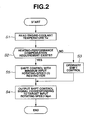
- FIG. 2 is a flowchart showing operation of the embodiment
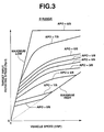
- FIG. 3 is a graph showing a shift map at ordinary shift control of the CVT
- FIG. 4 is a graph similar to FIG. 3, showing a shift map at heating-performance compensation of the CVT.
- FIG. 5 is a time chart showing a time-series change in input rotating speed of the CVT when stepless shift control is carried out for heating-performance compensation.
- the power train of the CVT-equipped vehicle comprises a CVT 1 such as V-belt CVT or toroidal CVT, an engine 2, a differential gear 3, and driving wheels 4.
- the CVT 1 is constructed so that its input shaft is coupled to an output shaft of the engine 2 through a torque converter T/C so as to receive engine rotation, which is provided under stepless shift ensured by a stepless shift mechanism 5.
- Converted output of the CVT 1 is provided to the driving wheels 4 via the differential gear 3 to drive the wheels 4, thus cruising the vehicle.
- the CVT 1 further comprises an engine-driven oil pump 6 and a control valve body 7 for shift-controlling the stepless shift mechanism 5 using as a medium hydraulic oil derived from the oil pump 6. Shift control of the CVT 1 through the control valve body 7 is carried out by a transmission electronic control unit (ECU) 11.
- ECU transmission electronic control unit
- the transmission ECU 11 receives a signal of an accelerator opening sensor 12 for sensing an accelerator-pedal depression amount (accelerator opening) APO, a signal of a vehicle-speed sensor 13 for sensing a vehicle speed VSP, a signal of an inhibitor switch 14 for detecting a selected range such as P, R, N, D or L range of the CVT 1 which a driver commands through a shift lever, and a signal of a coolant-temperature sensor 15 for sensing an engine-coolant temperature Tw.
- a signal of an accelerator opening sensor 12 for sensing an accelerator-pedal depression amount (accelerator opening) APO
- a vehicle-speed sensor 13 for sensing a vehicle speed VSP
- a signal of an inhibitor switch 14 for detecting a selected range such as P, R, N, D or L range of the CVT 1 which a driver commands through a shift lever
- a signal of a coolant-temperature sensor 15 for sensing an engine-coolant temperature Tw.
- the transmission ECU 11 carries out well-known computation in accordance with information input from the sensors to ensure shift control, the outline of which is described hereafter.
- First, an optimum line pressure for current cruising conditions is determined in accordance with the accelerator opening APO, vehicle speed VSP, and selected range to provide its signal to a line-pressure solenoid, not shown, of the control valve body 7.
- the line-pressure solenoid adjusts hydraulic oil derived from the oil pump 6 at the pressure corresponding to the signal, which serves as source pressure for shift control.
- the transmission ECU 11 calculates a target input rotating speed Npri of the CVT 1 in accordance with the accelerator opening APO, vehicle speed VSP, and selected range.
- the shift range is D range
- the target rotating speed Npri is obtained out of the accelerator opening APO and the vehicle speed VSP based on a predetermined shift map as shown in FIG. 3.
- a shift control signal for achieving the target rotating speed Npri is provided to a shift actuator such as a stepping motor, not shown, in the control valve body 7.
- the target rotating speed Npri divided by an output rotating speed is a target shift ratio.
- the shift actuator carries out through a shift control valve, not shown, in the control valve body 7 conversion of the CVT 1 to the target rotating speed Npri (target shift ratio).
- shift is terminated to maintain the target rotating speed Npri.
- the transmission ECU determines in accordance with the accelerator opening APO, vehicle speed VSP, and selected range whether or not the torque converter T/C should be put in the lockup state in which their input/output elements (pump impeller and turbine runner) are coupled directly, or in the converter state in which the direct coupling is released. And a corresponding lockup signal is provided to a lockup solenoid, not shown, in the control valve body 7.
- the lockup solenoid puts through a lockup control valve, not shown, in the control valve body 7 the torque converter T/C in the lockup state or in the converter state.
- the transmission ECU 11 carries out a control program as shown in FIG. 2 to ensure shift control at presence of heating-performance compensation requirement, which the present invention targets.
- read is engine-coolant temperature Tw sensed by the coolant-temperature sensor 15 shown in FIG. 1.
- flow proceeds to a step S3 where the shift control at ordinary time is carried out.
- a shift control signal corresponding to the target rotating speed Npri (target shift ratio) is provided to the shift actuator.
- Npri target shift ratio
- a D-range shift control map at presence of heating-performance compensation requirement as shown in FIG. 4 is used in place of the D-range shift control map at ordinary time as shown in FIG. 3.
- the D-range shift control map at presence of heating-performance compensation requirement is obtained by adding a lower limit value data ⁇ of the input rotating speed determined for carrying out heating-performance compensation to the same map as the D-range shift control map at ordinary time as shown in FIG. 3.
- This lower limit value data ⁇ is a lower limit value determined to restrain degradation of the drivability and shift quality while compensating the heating performance every vehicle speed.
- the lower limit value data ⁇ is determined to maximally achieve heating-performance compensation.
- the lower limit value data ⁇ is determined to have a value equal to a lower limit value of the second boundary vehicle speed VSP2 between the ordinary vehicle-speed range and the high vehicle-speed range over the entire vehicle-speed range so as to restrain degradation of the drivability while compensating the heating performance.
- the lower limit value data ⁇ is determined to gradually decrease with reduction in the vehicle speed from a lower limit value of the first boundary vehicle speed VSP1 between the ordinary vehicle-speed range and the low vehicle-speed range so as to ensure smooth shift.
- VSP1 40Km/h
- VSP2 70Km/h
- the reason why the lower limit value data ⁇ of the input rotating speed for heating-performance compensation in the high vehicle-speed range is kept at a value equal to a lower limit value of the second boundary vehicle speed VSP2 between the ordinary vehicle-speed range and the high vehicle-speed range over the entire vehicle-speed range is as follows.
- the lower limit value data ⁇ may be lowered as the vehicle speed VSP becomes higher since the input rotating speed is high per se in the high vehicle-speed range.
- the lower limit value data ⁇ in the high vehicle-speed range is determined to have a value equal to a lower limit value of the second boundary vehicle speed VSP2 between the ordinary vehicle-speed range and the high vehicle-speed range over the entire vehicle-speed range.
- the reason why the lower limit value data ⁇ of the input rotating speed for heating-performance compensation in the low vehicle-speed range is determined to gradually decrease with reduction in the vehicle speed from a lower limit value of the first boundary vehicle speed VSP1 between the ordinary vehicle-speed range and the low vehicle-speed range is as follows.
- the lower limit value data ⁇ in the low vehicle-speed range should be kept at a value equal to a lower limit value of the first boundary vehicle speed VSP1 as shown by broken line ⁇ in FIG. 4.
- the lower limit value data ⁇ in the low vehicle-speed range is determined to gradually decrease with reduction in the vehicle speed from a lower limit value of the first boundary vehicle speed VSP1 so as to ensure smooth shift even at the time of shift from the maximum low shift ratio.
- a signal indicative of the target input rotating speed Npri (target shift ratio) is obtained to shift-control the CVT 1 in the aforementioned way while avoiding the transmission input rotating speed from being below the lower limit value data ⁇ of the input rotating speed for heating-performance compensation in FIG. 4.
- a shift control signal corresponding to the signal indicative of the target input rotating speed Npri is provided to the shift actuator.
- the CVT 1 when the heating-performance compensation requirement exists, the CVT 1 is shift-controlled in such as way as to avoid input rotation of the CVT 1 from being below the lower limit value ⁇ (refer to FIG. 4) determined to restrain degradation of the drivability and shift quality while compensating the heating performance every vehicle speed. Therefore, input rotation of the CVT 1 and thus engine rotation will not be below the lower limit value ⁇ for restraining degradation of the drivability and shift quality while compensating the heating performance every vehicle speed, resulting in not only possible restraint in degradation of the drivability and shift quality while compensating the heating performance every vehicle speed, but achievement of proper and correct transmission input rotation with respect to a rotating speed required therefor without any excess or shortage.
- transmission input rotation at presence of heating-performance compensation requirement may not be too high or too low with respect to the heating-performance compensation requirement, allowing not only resolution of the problem raise when transmission input rotation is too high, i.e. problem of degradation of the drivability and shift quality and/or occurrence of large noise due to increase in transmission input rotation greater than necessary, but resolution of the problem raised when transmission input rotation is too low, i.e. problem of impossible compensation of the heating performance as required and thus less comfortable space of the vehicle.
- the lower limit value ⁇ for heating-performance compensation of the input rotating speed is determined to maximally achieve heating-performance compensation.
- the lower limit value ⁇ is determined to have a value equal to a lower limit value of the second boundary vehicle speed between the ordinary vehicle-speed range and the high vehicle-speed range over the entire vehicle-speed range.
- the lower limit value ⁇ is determined to gradually decrease with reduction in the vehicle speed from a lower limit value of the first boundary vehicle speed between the ordinary vehicle-speed range and the low vehicle-speed range.
- shift control is such that a transmission input rotating speed increases sharply immediately after the heating-performance compensation requirement occurs, and it decreases sharply immediately after the heating-performance compensation requirement disappears, resulting in possible occurrence of a shock.
- the following transition control of the CVT 1 is preferably carried out to solve this problem. Specifically, at instant t1 when the heating-performance compensation requirement occurs, without increasing at one stroke a transmission input rotating speed from the rotating speed at ordinary shift to the minimum input rotating speed ⁇ for heating-performance compensation, a transmission input rotating speed is gradually increased at a given gradient ⁇ 1 to attain the minimum input rotating speed ⁇ at instant t2.
Landscapes
- Engineering & Computer Science (AREA)
- General Engineering & Computer Science (AREA)
- Mechanical Engineering (AREA)
- Physics & Mathematics (AREA)
- Thermal Sciences (AREA)
- Automation & Control Theory (AREA)
- Transportation (AREA)
- Control Of Transmission Device (AREA)
- Air-Conditioning For Vehicles (AREA)
Applications Claiming Priority (1)
| Application Number | Priority Date | Filing Date | Title |
|---|---|---|---|
| JP2004289104A JP4157087B2 (ja) | 2004-09-30 | 2004-09-30 | 無段変速機搭載車の暖房性能補償装置 |
Publications (3)
| Publication Number | Publication Date |
|---|---|
| EP1643163A2 true EP1643163A2 (fr) | 2006-04-05 |
| EP1643163A3 EP1643163A3 (fr) | 2010-04-28 |
| EP1643163B1 EP1643163B1 (fr) | 2011-11-09 |
Family
ID=35478868
Family Applications (1)
| Application Number | Title | Priority Date | Filing Date |
|---|---|---|---|
| EP05020464A Ceased EP1643163B1 (fr) | 2004-09-30 | 2005-09-20 | Dispositif et méthode de compensation de performance de rechauffage d'une tranmsission à variation continue |
Country Status (3)
| Country | Link |
|---|---|
| US (1) | US7445579B2 (fr) |
| EP (1) | EP1643163B1 (fr) |
| JP (1) | JP4157087B2 (fr) |
Cited By (1)
| Publication number | Priority date | Publication date | Assignee | Title |
|---|---|---|---|---|
| EP2165904A3 (fr) * | 2008-09-19 | 2012-07-25 | GM Global Technology Operations LLC | Procédé et appareil pour contrôler la température de moteur pour une transmission hybride |
Families Citing this family (6)
| Publication number | Priority date | Publication date | Assignee | Title |
|---|---|---|---|---|
| US7909721B2 (en) * | 2006-06-09 | 2011-03-22 | Saturn Electronics & Engineering, Inc. | Fluid pressure control assembly |
| US8267837B2 (en) * | 2007-11-07 | 2012-09-18 | GM Global Technology Operations LLC | Method and apparatus to control engine temperature for a hybrid powertrain |
| US8403811B2 (en) * | 2010-04-12 | 2013-03-26 | Ford Global Technologies, Llc | Method and system for cabin heating |
| JP2014005894A (ja) * | 2012-06-26 | 2014-01-16 | Suzuki Motor Corp | 自動変速機の変速制御装置 |
| US10407069B2 (en) * | 2017-04-21 | 2019-09-10 | Ford Global Technologies, Llc | Methods and system for controlling engine braking |
| CN111492129B (zh) * | 2017-12-15 | 2022-01-04 | 日产自动车株式会社 | 发动机冷却水温度的控制方法及控制装置 |
Citations (1)
| Publication number | Priority date | Publication date | Assignee | Title |
|---|---|---|---|---|
| JP2000179670A (ja) | 1998-12-17 | 2000-06-27 | Toyota Motor Corp | 車両用空調機の制御装置 |
Family Cites Families (9)
| Publication number | Priority date | Publication date | Assignee | Title |
|---|---|---|---|---|
| JPS58189713A (ja) * | 1982-04-30 | 1983-11-05 | Toyota Motor Corp | 車両用動力装置 |
| JPS59219553A (ja) * | 1983-05-27 | 1984-12-10 | Nissan Motor Co Ltd | 無段変速機の変速制御装置 |
| JPH066979B2 (ja) * | 1983-08-22 | 1994-01-26 | トヨタ自動車株式会社 | 車両用無段変速機の制御装置 |
| JPH0712810B2 (ja) * | 1985-05-28 | 1995-02-15 | トヨタ自動車株式会社 | 車両用無段変速機の速度比制御装置 |
| JP2541821B2 (ja) * | 1987-06-30 | 1996-10-09 | 富士重工業株式会社 | 無段変速機の変速制御装置 |
| US5146891A (en) * | 1989-12-13 | 1992-09-15 | Nissan Motor Company, Limited | System and method for controlling fuel supply to internal combustion engine according to operation of automatic transmision applicable to automotive vehicle |
| JP4119223B2 (ja) * | 2002-10-29 | 2008-07-16 | ジヤトコ株式会社 | 車両用無段変速機の変速比制御装置 |
| JP2004239334A (ja) | 2003-02-05 | 2004-08-26 | Nissan Motor Co Ltd | 無段変速機制御装置 |
| JP2004340294A (ja) * | 2003-05-16 | 2004-12-02 | Suzuki Motor Corp | 自動二輪車用無段変速装置の制御装置 |
-
2004
- 2004-09-30 JP JP2004289104A patent/JP4157087B2/ja not_active Expired - Fee Related
-
2005
- 2005-09-20 EP EP05020464A patent/EP1643163B1/fr not_active Ceased
- 2005-09-29 US US11/237,903 patent/US7445579B2/en not_active Expired - Lifetime
Patent Citations (1)
| Publication number | Priority date | Publication date | Assignee | Title |
|---|---|---|---|---|
| JP2000179670A (ja) | 1998-12-17 | 2000-06-27 | Toyota Motor Corp | 車両用空調機の制御装置 |
Cited By (1)
| Publication number | Priority date | Publication date | Assignee | Title |
|---|---|---|---|---|
| EP2165904A3 (fr) * | 2008-09-19 | 2012-07-25 | GM Global Technology Operations LLC | Procédé et appareil pour contrôler la température de moteur pour une transmission hybride |
Also Published As
| Publication number | Publication date |
|---|---|
| JP4157087B2 (ja) | 2008-09-24 |
| US7445579B2 (en) | 2008-11-04 |
| US20060068971A1 (en) | 2006-03-30 |
| EP1643163A3 (fr) | 2010-04-28 |
| EP1643163B1 (fr) | 2011-11-09 |
| JP2006105178A (ja) | 2006-04-20 |
Similar Documents
| Publication | Publication Date | Title |
|---|---|---|
| US6181020B1 (en) | Integrated driving torque control system for automotive vehicles with continuously variable automatic transmission | |
| EP0879731B1 (fr) | Dispositif de commande pour moteur et transmission à variation continue automatique à commande électronique | |
| EP1950464B1 (fr) | Dispositif de contrôle pour une transmission automatique de véhicule | |
| US8326503B2 (en) | Lock-up clutch control device | |
| US4836056A (en) | Control apparatus for vehicle power transmitting system including continuously variable transmission | |
| EP0093313B1 (fr) | Procédé pour varier le rapport de réduction d'une transmission à variation continue, avec considération de la température du radiateur | |
| US6757603B2 (en) | Slippage prevention apparatus of belt-drive continuously variable transmission for automotive vehicle | |
| US7988595B2 (en) | Control device for automatic transmission for vehicle | |
| US5245541A (en) | System for and method of controlling automatic transmission | |
| US6454676B1 (en) | Control system for internal combustion engine equipped with automatic transmission | |
| US7445579B2 (en) | System and method of compensating heating performance of continuously-variable-transmission-equipped vehicle | |
| US5209332A (en) | Control system for a clutch of a motor vehicle | |
| EP2053281A2 (fr) | Appareil de contrôle de véhicule | |
| JP3460528B2 (ja) | 車両の駆動力制御装置 | |
| US4825991A (en) | Control system for a clutch for a vehicle | |
| US6793606B2 (en) | Shift control method for shifting an automatic transmission to a forward driving range while driving in a reverse driving range | |
| JP4576821B2 (ja) | 車両用ロックアップクラッチの制御装置 | |
| KR100345130B1 (ko) | 차량용 자동 변속기의 라인압 제어 방법 | |
| US6383117B1 (en) | Damper clutch control method for automatic transmission | |
| US4830155A (en) | Control system for a clutch for a vehicle | |
| JPH0579556A (ja) | 車両用自動変速機の変速制御装置 | |
| JPH08277932A (ja) | ロックアップクラッチ制御装置および方法 | |
| JPH01224526A (ja) | 油圧式クラッチの制御装置 | |
| JP3652538B2 (ja) | 自動変速機の制御装置 | |
| JP5211299B2 (ja) | 動力伝達部の制御装置 |
Legal Events
| Date | Code | Title | Description |
|---|---|---|---|
| PUAI | Public reference made under article 153(3) epc to a published international application that has entered the european phase |
Free format text: ORIGINAL CODE: 0009012 |
|
| 17P | Request for examination filed |
Effective date: 20050920 |
|
| AK | Designated contracting states |
Kind code of ref document: A2 Designated state(s): AT BE BG CH CY CZ DE DK EE ES FI FR GB GR HU IE IS IT LI LT LU LV MC NL PL PT RO SE SI SK TR |
|
| AX | Request for extension of the european patent |
Extension state: AL BA HR MK YU |
|
| PUAL | Search report despatched |
Free format text: ORIGINAL CODE: 0009013 |
|
| AK | Designated contracting states |
Kind code of ref document: A3 Designated state(s): AT BE BG CH CY CZ DE DK EE ES FI FR GB GR HU IE IS IT LI LT LU LV MC NL PL PT RO SE SI SK TR |
|
| AX | Request for extension of the european patent |
Extension state: AL BA HR MK YU |
|
| AKX | Designation fees paid |
Designated state(s): DE FR GB IT |
|
| GRAP | Despatch of communication of intention to grant a patent |
Free format text: ORIGINAL CODE: EPIDOSNIGR1 |
|
| RIC1 | Information provided on ipc code assigned before grant |
Ipc: F16H 57/04 20100101ALI20110214BHEP Ipc: F16H 61/00 20060101AFI20110214BHEP |
|
| GRAS | Grant fee paid |
Free format text: ORIGINAL CODE: EPIDOSNIGR3 |
|
| GRAA | (expected) grant |
Free format text: ORIGINAL CODE: 0009210 |
|
| AK | Designated contracting states |
Kind code of ref document: B1 Designated state(s): DE FR GB IT |
|
| REG | Reference to a national code |
Ref country code: GB Ref legal event code: FG4D |
|
| REG | Reference to a national code |
Ref country code: DE Ref legal event code: R096 Ref document number: 602005031067 Country of ref document: DE Effective date: 20120202 |
|
| PG25 | Lapsed in a contracting state [announced via postgrant information from national office to epo] |
Ref country code: IT Free format text: LAPSE BECAUSE OF FAILURE TO SUBMIT A TRANSLATION OF THE DESCRIPTION OR TO PAY THE FEE WITHIN THE PRESCRIBED TIME-LIMIT Effective date: 20111109 |
|
| PLBE | No opposition filed within time limit |
Free format text: ORIGINAL CODE: 0009261 |
|
| STAA | Information on the status of an ep patent application or granted ep patent |
Free format text: STATUS: NO OPPOSITION FILED WITHIN TIME LIMIT |
|
| 26N | No opposition filed |
Effective date: 20120810 |
|
| REG | Reference to a national code |
Ref country code: DE Ref legal event code: R097 Ref document number: 602005031067 Country of ref document: DE Effective date: 20120810 |
|
| GBPC | Gb: european patent ceased through non-payment of renewal fee |
Effective date: 20120920 |
|
| PG25 | Lapsed in a contracting state [announced via postgrant information from national office to epo] |
Ref country code: GB Free format text: LAPSE BECAUSE OF NON-PAYMENT OF DUE FEES Effective date: 20120920 |
|
| REG | Reference to a national code |
Ref country code: DE Ref legal event code: R082 Ref document number: 602005031067 Country of ref document: DE Representative=s name: GRUENECKER, KINKELDEY, STOCKMAIR & SCHWANHAEUS, DE |
|
| REG | Reference to a national code |
Ref country code: DE Ref legal event code: R081 Ref document number: 602005031067 Country of ref document: DE Owner name: NISSAN MOTOR CO., LTD., JP Free format text: FORMER OWNER: JATCO LTD, FUJI, JP Effective date: 20140124 Ref country code: DE Ref legal event code: R081 Ref document number: 602005031067 Country of ref document: DE Owner name: JATCO LTD, JP Free format text: FORMER OWNER: JATCO LTD, FUJI, JP Effective date: 20140124 Ref country code: DE Ref legal event code: R081 Ref document number: 602005031067 Country of ref document: DE Owner name: JATCO LTD, JP Free format text: FORMER OWNER: JATCO LTD, FUJI, JP Effective date: 20111212 Ref country code: DE Ref legal event code: R081 Ref document number: 602005031067 Country of ref document: DE Owner name: NISSAN MOTOR CO., LTD., JP Free format text: FORMER OWNER: JATCO LTD, FUJI, JP Effective date: 20111212 Ref country code: DE Ref legal event code: R082 Ref document number: 602005031067 Country of ref document: DE Representative=s name: GRUENECKER, KINKELDEY, STOCKMAIR & SCHWANHAEUS, DE Effective date: 20140124 Ref country code: DE Ref legal event code: R081 Ref document number: 602005031067 Country of ref document: DE Owner name: NISSAN MOTOR CO., LTD., YOKOHAMA-SHI, JP Free format text: FORMER OWNER: JATCO LTD, FUJI, SHIZUOKA, JP Effective date: 20140124 Ref country code: DE Ref legal event code: R081 Ref document number: 602005031067 Country of ref document: DE Owner name: JATCO LTD, FUJI, JP Free format text: FORMER OWNER: JATCO LTD, FUJI, SHIZUOKA, JP Effective date: 20111212 Ref country code: DE Ref legal event code: R081 Ref document number: 602005031067 Country of ref document: DE Owner name: NISSAN MOTOR CO., LTD., YOKOHAMA-SHI, JP Free format text: FORMER OWNER: JATCO LTD, FUJI, SHIZUOKA, JP Effective date: 20111212 Ref country code: DE Ref legal event code: R081 Ref document number: 602005031067 Country of ref document: DE Owner name: JATCO LTD, FUJI, JP Free format text: FORMER OWNER: JATCO LTD, FUJI, SHIZUOKA, JP Effective date: 20140124 Ref country code: DE Ref legal event code: R082 Ref document number: 602005031067 Country of ref document: DE Representative=s name: GRUENECKER PATENT- UND RECHTSANWAELTE PARTG MB, DE Effective date: 20140124 |
|
| REG | Reference to a national code |
Ref country code: FR Ref legal event code: TQ Owner name: NISSAN MOTOR CO., LTD, JP Effective date: 20140217 Ref country code: FR Ref legal event code: TQ Owner name: JATCO LTD, JP Effective date: 20140217 |
|
| REG | Reference to a national code |
Ref country code: FR Ref legal event code: PLFP Year of fee payment: 12 |
|
| REG | Reference to a national code |
Ref country code: FR Ref legal event code: PLFP Year of fee payment: 13 |
|
| REG | Reference to a national code |
Ref country code: FR Ref legal event code: PLFP Year of fee payment: 14 |
|
| PGFP | Annual fee paid to national office [announced via postgrant information from national office to epo] |
Ref country code: FR Payment date: 20180813 Year of fee payment: 14 Ref country code: DE Payment date: 20180904 Year of fee payment: 14 |
|
| REG | Reference to a national code |
Ref country code: DE Ref legal event code: R119 Ref document number: 602005031067 Country of ref document: DE |
|
| PG25 | Lapsed in a contracting state [announced via postgrant information from national office to epo] |
Ref country code: DE Free format text: LAPSE BECAUSE OF NON-PAYMENT OF DUE FEES Effective date: 20200401 |
|
| PG25 | Lapsed in a contracting state [announced via postgrant information from national office to epo] |
Ref country code: FR Free format text: LAPSE BECAUSE OF NON-PAYMENT OF DUE FEES Effective date: 20190930 |