EP1643175A2 - Actionneur pneumatique d'une soupape - Google Patents
Actionneur pneumatique d'une soupape Download PDFInfo
- Publication number
- EP1643175A2 EP1643175A2 EP06000177A EP06000177A EP1643175A2 EP 1643175 A2 EP1643175 A2 EP 1643175A2 EP 06000177 A EP06000177 A EP 06000177A EP 06000177 A EP06000177 A EP 06000177A EP 1643175 A2 EP1643175 A2 EP 1643175A2
- Authority
- EP
- European Patent Office
- Prior art keywords
- end wall
- bushing
- wall
- cylindrical
- pneumatic valve
- Prior art date
- Legal status (The legal status is an assumption and is not a legal conclusion. Google has not performed a legal analysis and makes no representation as to the accuracy of the status listed.)
- Granted
Links
Images


Classifications
-
- F—MECHANICAL ENGINEERING; LIGHTING; HEATING; WEAPONS; BLASTING
- F16—ENGINEERING ELEMENTS AND UNITS; GENERAL MEASURES FOR PRODUCING AND MAINTAINING EFFECTIVE FUNCTIONING OF MACHINES OR INSTALLATIONS; THERMAL INSULATION IN GENERAL
- F16K—VALVES; TAPS; COCKS; ACTUATING-FLOATS; DEVICES FOR VENTING OR AERATING
- F16K27/00—Construction of housing; Use of materials therefor
- F16K27/02—Construction of housing; Use of materials therefor of lift valves
-
- F—MECHANICAL ENGINEERING; LIGHTING; HEATING; WEAPONS; BLASTING
- F16—ENGINEERING ELEMENTS AND UNITS; GENERAL MEASURES FOR PRODUCING AND MAINTAINING EFFECTIVE FUNCTIONING OF MACHINES OR INSTALLATIONS; THERMAL INSULATION IN GENERAL
- F16K—VALVES; TAPS; COCKS; ACTUATING-FLOATS; DEVICES FOR VENTING OR AERATING
- F16K31/00—Actuating devices; Operating means; Releasing devices
- F16K31/12—Actuating devices; Operating means; Releasing devices actuated by fluid
- F16K31/122—Actuating devices; Operating means; Releasing devices actuated by fluid the fluid acting on a piston
- F16K31/1221—Actuating devices; Operating means; Releasing devices actuated by fluid the fluid acting on a piston one side of the piston being spring-loaded
Definitions
- the invention relates to a pneumatic valve drive with a housing having a cylinder in which a piston connected to an axial spindle is axially guided and sealed at its periphery against the inner wall of the cylinder.
- Such pneumatic valve actuators have been used successfully for many years in industrial process control.
- the present invention improves these valve actuators in several aspects.
- the housing of the valve drive has a separate cylindrical bushing and at each axial end of the bush a plastic end wall.
- a piston connected to an axial spindle is axially guided in the bushing and sealed at its periphery against the inner wall of the bushing.
- On one of the end walls a first cylindrical outer wall part is formed.
- a second cylindrical outer wall part is formed, which is bolted to the first outer wall part.
- the outer wall parts are surrounded by a cylindrical shell of a thin-walled stainless steel, which is inserted axially between the end walls and optionally braced between them.
- the bushing can in turn be axially clamped between the end walls.
- the housing of the valve drive can thus be made of a relatively inexpensive plastic, although the entire lateral surface of the valve drive is equipped with optical and hygienic properties that meet high standards, so that an application of the valve drive is made possible in an environment that makes high demands in this regard For example, in the field of pharmaceutical technology, biotechnology or food processing. Conventional valve actuators for this application have solid stainless steel housings and are therefore much more expensive.
- pneumatic air ducts for supply air, exhaust air and control air are integrated in the housing of the valve drive.
- an axial control air channel is formed between the outer surface of the bushing and the inner surface of one of the outer wall parts, which opens into the space between the other end wall and the piston.
- the housing of the valve drive actuation module includes a pneumatic control valve and a pneumatic manifold block which selectively connect the control air passage to a compressed air passage or to an exhaust passage.
- Compressed air duct and exhaust duct are preferably formed in the end wall, to which the control head is attached.
- a pneumatic valve actuator having a housing having a cylinder and an end wall at each axial end of the cylinder.
- a piston connected to an axial spindle is axially guided in the cylinder and sealed at its periphery against the cylinder.
- At one of the end walls closes a control module which is integrated with the valve drive to a unitary device.
- This control module may include pneumatic and / or electrical and / or mechanical control means of various kinds.
- FIG. 1 Shown in Figure 1 is a designated generally by 10 pneumatic valve drive with an attached on one end face control head 12 and connected on its other end face valve fitting 14.
- the control head 12 is only one example of a variety of pneumatic or electrical / electronic control modules, the can be combined with the valve actuator 10.
- the valve drive has a housing which is composed essentially of two parts.
- the first housing part comprises an end wall 20 with a molded cylindrical outer wall part 22.
- the second housing part comprises an end wall 24 with a molded cylindrical outer wall part 26.
- a cylindrical bushing 28 is axially clamped. Inside the bushing 28, a piston 30 is guided, which is sealed at its periphery against the inner surface of the bush 28.
- the piston 30 is acted upon by a supported on the end wall 20 compression spring 32 to the end wall 24 out.
- a spindle 34 is connected, which carries a valve member 36 at its free end.
- the cylindrical outer wall parts 22, 26 are screwed together and surrounded the bushing 28.
- the outer wall parts 22, 26 are in turn surrounded by a cylindrical shell 38, which consists of a thin-walled stainless steel.
- the shell 38 is axially braced between the end walls 20, 24 and sealed by a respective seal.
- the sheath 38 closes virtually without gaps on the end wall 24 and on the circumference of the end wall 20. It gives the valve drive a high-quality appearance and at the same time meets the high standards of material quality and shape design that are used in industrial areas such as pharmaceutical technology, biotechnology and food processing.
- the end wall 20 forms on its side facing away from the piston 30 side a uniform interface for a variety of designs of control heads.
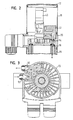
- the control head shown in Figure 1 and Figure 2 includes a pneumatic control valve 40 and a pneumatic control block 42. Further, it includes a position sensor 44 which is connected to the piston 30 by a coaxially protruding the end wall 20 coupling clip 46.
- Figure 3 shows an exhaust duct 50, which opens at the outer periphery of the end wall 20, and a supply air channel 52, which also opens on the outer periphery of the end wall 20.
- These channels 50, 52 are connected to the pneumatic manifold block 42, which in turn is connected to the pneumatic control valve.
- a control air passage extends through the manifold block 42 to a bore 54 axially traversing the end wall 20 which continues in a pilot air passage 56 extending between the outer periphery of the bush 28 and the inner surface of the outer wall member 26.
- the control air channel 56 opens into the cylinder space below the piston 30.
- the end wall 24 forms with its side facing away from the piston 30 end face a uniform interface for connecting various designs of valve fittings.
- a valve fitting with the valve body 36 for a seat valve is shown.
- Figure 4 shows at 60 the screwing of the outer wall part 22 with the outer wall part 26, the sealing of these wall parts together by an inserted ring seal 62 and the clamping and sealing of the bushing 28 with a ring seal 64 which is inserted into a groove of the end wall 20. Furthermore, the connection of the cylindrical shell 38 can be seen at the transition between the end wall 20 and outer wall part 22 with the insertion of a seal 66.
- the control head 12 has a similar appearance as the valve drive 10.
- he also has a cylindrical shell 70, which consists of a thin-walled stainless steel. It is clamped axially between the end wall 20 and an opposite cover 72.
- the lid 72 can be attached directly to the end wall 20, which also forms a suitable interface for this cover 72, as shown in Figure 5.
Landscapes
- Engineering & Computer Science (AREA)
- General Engineering & Computer Science (AREA)
- Mechanical Engineering (AREA)
- Actuator (AREA)
- Fluid-Driven Valves (AREA)
- Valve Housings (AREA)
- Multiple-Way Valves (AREA)
Applications Claiming Priority (2)
| Application Number | Priority Date | Filing Date | Title |
|---|---|---|---|
| DE10336065A DE10336065A1 (de) | 2003-08-06 | 2003-08-06 | Pneumatischer Ventilantrieb |
| EP20040017860 EP1505325B1 (fr) | 2003-08-06 | 2004-07-28 | Actionneur pneumatique d'une soupape |
Related Parent Applications (2)
| Application Number | Title | Priority Date | Filing Date |
|---|---|---|---|
| EP04017860.0 Division | 2004-07-28 | ||
| EP20040017860 Division EP1505325B1 (fr) | 2003-08-06 | 2004-07-28 | Actionneur pneumatique d'une soupape |
Publications (3)
| Publication Number | Publication Date |
|---|---|
| EP1643175A2 true EP1643175A2 (fr) | 2006-04-05 |
| EP1643175A3 EP1643175A3 (fr) | 2009-03-11 |
| EP1643175B1 EP1643175B1 (fr) | 2011-02-09 |
Family
ID=33547108
Family Applications (2)
| Application Number | Title | Priority Date | Filing Date |
|---|---|---|---|
| EP20040017860 Expired - Lifetime EP1505325B1 (fr) | 2003-08-06 | 2004-07-28 | Actionneur pneumatique d'une soupape |
| EP06000177A Expired - Lifetime EP1643175B1 (fr) | 2003-08-06 | 2004-07-28 | Actionneur pneumatique d'une soupape |
Family Applications Before (1)
| Application Number | Title | Priority Date | Filing Date |
|---|---|---|---|
| EP20040017860 Expired - Lifetime EP1505325B1 (fr) | 2003-08-06 | 2004-07-28 | Actionneur pneumatique d'une soupape |
Country Status (2)
| Country | Link |
|---|---|
| EP (2) | EP1505325B1 (fr) |
| DE (3) | DE10336065A1 (fr) |
Cited By (6)
| Publication number | Priority date | Publication date | Assignee | Title |
|---|---|---|---|---|
| EP2016318A1 (fr) | 2006-05-10 | 2009-01-21 | GEA Tuchenhagen GmbH | Structure modulaire de boitier pour des systemes de surveillance, de commande et de regulation pour une soupape de processus |
| CN100540961C (zh) * | 2007-12-14 | 2009-09-16 | 苏州有色金属研究院有限公司 | 气缸式喷射阀 |
| US8813778B2 (en) | 2012-02-27 | 2014-08-26 | Buerkert Werke Gmbh | Manually actuated control module |
| WO2016037795A1 (fr) * | 2014-09-11 | 2016-03-17 | Festo Ag & Co. Kg | Système de commande de soupape |
| DE102014013390A1 (de) | 2014-09-11 | 2016-03-17 | Festo Ag & Co. Kg | Pneumatischer Ventilantrieb |
| CN107676529A (zh) * | 2016-08-02 | 2018-02-09 | 费斯托股份有限两合公司 | 阀操纵系统 |
Families Citing this family (14)
| Publication number | Priority date | Publication date | Assignee | Title |
|---|---|---|---|---|
| DE102008023748B4 (de) | 2008-05-15 | 2011-01-20 | Armaturenwerk Hötensleben GmbH | Steuerkopf und Dichtung für einen pneumatischen Antrieb |
| DE202009012182U1 (de) * | 2009-09-08 | 2009-12-10 | Bürkert Werke GmbH & Co.KG | Ansteuermodul |
| DE202010003659U1 (de) | 2010-03-16 | 2010-07-15 | Bürkert Werke GmbH | Vorrichtung zur Endlagenerkennung in Hubventilen, Ventilbausatz sowie Sensormodul hierfür |
| DE102010050662A1 (de) * | 2010-11-09 | 2012-05-10 | Festo Ag & Co. Kg | Steuerkopf für ein fluidisch ansteuerbares Ventil |
| DE102012003231B3 (de) * | 2012-02-20 | 2013-03-21 | Festo Ag & Co. Kg | Prozessventil |
| DE102012003230B3 (de) * | 2012-02-20 | 2013-03-21 | Festo Ag & Co. Kg | Prozessventil |
| DE102014004669B3 (de) | 2014-03-31 | 2015-09-24 | Festo Ag & Co. Kg | Ventil |
| DE102015209083A1 (de) * | 2015-05-19 | 2016-11-24 | Gemü Gebr. Müller Apparatebau Gmbh & Co. Kommanditgesellschaft | Ventilantrieb |
| DE102016200396B3 (de) | 2016-01-14 | 2016-08-25 | Festo Ag & Co. Kg | Ventilbetätigungssystem |
| US10180197B1 (en) | 2017-09-07 | 2019-01-15 | Honeywell International Inc. | Protective housing for configuring a programming module of an industrial product |
| DE102017123376B4 (de) | 2017-10-09 | 2024-06-06 | Bürkert Werke GmbH & Co. KG | Ventilantriebssystem für ein pneumatisches oder hydraulisches Ventil |
| DE102018217986B3 (de) | 2018-10-22 | 2019-09-05 | Festo Ag & Co. Kg | Pneumatiksteller |
| US12249821B2 (en) | 2020-07-24 | 2025-03-11 | Schneider Electric USA, Inc. | Plug-on service-entrance neutral device |
| DE102023129019A1 (de) | 2023-10-23 | 2025-04-24 | Sisto Armaturen S.A. | Pneumatik-Konzept Endschalter-Box |
Citations (1)
| Publication number | Priority date | Publication date | Assignee | Title |
|---|---|---|---|---|
| DE19641073A1 (de) | 1996-10-04 | 1998-04-16 | Adolf Harald Sonnleitner | Druckmittelbetätigbares Ventil |
Family Cites Families (5)
| Publication number | Priority date | Publication date | Assignee | Title |
|---|---|---|---|---|
| GB9004391D0 (en) * | 1990-02-27 | 1990-04-25 | Timmins John A | Simplified valve control |
| DE9307166U1 (de) * | 1993-05-11 | 1993-07-15 | Bürkert GmbH & Co Werk Ingelfingen, 7118 Ingelfingen | Sperrventil |
| US6086040A (en) * | 1997-11-07 | 2000-07-11 | Apv Fluid Handling Horsens A/S | Valve and a pneumatic control valve non-rotatably joined by a coupling |
| JP4418571B2 (ja) * | 2000-04-11 | 2010-02-17 | シーケーディ株式会社 | 高温対応ガス制御バルブ |
| JP3553526B2 (ja) * | 2001-06-27 | 2004-08-11 | 株式会社キッツエスシーティー | 可変流量バルブ |
-
2003
- 2003-08-06 DE DE10336065A patent/DE10336065A1/de not_active Withdrawn
-
2004
- 2004-07-28 EP EP20040017860 patent/EP1505325B1/fr not_active Expired - Lifetime
- 2004-07-28 EP EP06000177A patent/EP1643175B1/fr not_active Expired - Lifetime
- 2004-07-28 DE DE200450001990 patent/DE502004001990D1/de not_active Expired - Lifetime
- 2004-07-28 DE DE200450012179 patent/DE502004012179D1/de not_active Expired - Lifetime
Patent Citations (1)
| Publication number | Priority date | Publication date | Assignee | Title |
|---|---|---|---|---|
| DE19641073A1 (de) | 1996-10-04 | 1998-04-16 | Adolf Harald Sonnleitner | Druckmittelbetätigbares Ventil |
Cited By (11)
| Publication number | Priority date | Publication date | Assignee | Title |
|---|---|---|---|---|
| EP2016318A1 (fr) | 2006-05-10 | 2009-01-21 | GEA Tuchenhagen GmbH | Structure modulaire de boitier pour des systemes de surveillance, de commande et de regulation pour une soupape de processus |
| CN100540961C (zh) * | 2007-12-14 | 2009-09-16 | 苏州有色金属研究院有限公司 | 气缸式喷射阀 |
| US8813778B2 (en) | 2012-02-27 | 2014-08-26 | Buerkert Werke Gmbh | Manually actuated control module |
| WO2016037795A1 (fr) * | 2014-09-11 | 2016-03-17 | Festo Ag & Co. Kg | Système de commande de soupape |
| DE102014013390A1 (de) | 2014-09-11 | 2016-03-17 | Festo Ag & Co. Kg | Pneumatischer Ventilantrieb |
| CN106687730A (zh) * | 2014-09-11 | 2017-05-17 | 费斯托股份有限两合公司 | 阀操纵系统 |
| DE102014013391B4 (de) | 2014-09-11 | 2019-07-04 | Festo Ag & Co. Kg | Ventilbetätigungssystem |
| US10364911B2 (en) | 2014-09-11 | 2019-07-30 | Festo Ag & Co. Kg | Valve actuation system |
| CN107676529A (zh) * | 2016-08-02 | 2018-02-09 | 费斯托股份有限两合公司 | 阀操纵系统 |
| CN107676529B (zh) * | 2016-08-02 | 2019-11-05 | 费斯托股份有限两合公司 | 阀操纵系统 |
| US10584805B2 (en) | 2016-08-02 | 2020-03-10 | Festo Ag & Co. Kg | Valve actuating system |
Also Published As
| Publication number | Publication date |
|---|---|
| DE502004001990D1 (de) | 2006-12-28 |
| EP1643175A3 (fr) | 2009-03-11 |
| EP1643175B1 (fr) | 2011-02-09 |
| EP1505325A1 (fr) | 2005-02-09 |
| DE502004012179D1 (de) | 2011-03-24 |
| EP1505325B1 (fr) | 2006-11-15 |
| DE10336065A1 (de) | 2005-03-03 |
Similar Documents
| Publication | Publication Date | Title |
|---|---|---|
| EP1643175B1 (fr) | Actionneur pneumatique d'une soupape | |
| DE102007030006B4 (de) | Vakuumventil | |
| EP1200718B1 (fr) | Ensemble collecteur d'admission | |
| DE19918777A1 (de) | Schaltklappenverband aus montagegespritzten Schaltklappen oder Klappenmodulen | |
| DE29508401U1 (de) | Modularer Ventilaufbau | |
| EP1361382B1 (fr) | Ensemble de soupapes pour la commande de l'écoulement du matériau dans une installation de revêtement | |
| EP3995330B1 (fr) | Soupape de maintien de pression pour un ressort pneumatique et ressort pneumatique comprenant la soupape de maintien de pression | |
| EP1210165B1 (fr) | Filtre comportant un element soupape multifonctionnel | |
| DE3503444A1 (de) | Tandembremskraftverstaerker fuer kraftfahrzeuge | |
| DE102014012711A1 (de) | Ventileinheit zur Druckmodulation in einer Druckluft-Bremsanlage | |
| DE3338418C2 (fr) | ||
| EP3425248A1 (fr) | Servomoteur pour soupapes de processus | |
| EP1939461A2 (fr) | Vanne pneumatique modulaire à tiroir | |
| EP0994003A2 (fr) | Dispositif de soupape | |
| DE102005038621A1 (de) | Pneumatisches Wegeventil mit mindestens einem Ventilschieber | |
| EP0745796B1 (fr) | Robinet modulaire | |
| EP1998092A2 (fr) | Soupape électropneumatique, en particulier soupape pilote d'un distributeur pneumatique | |
| EP1696159B1 (fr) | Soupape à pince actionnée par fluide | |
| DE29518188U1 (de) | Blocksauger | |
| DE3722479A1 (de) | Magnetventil | |
| DE29822642U1 (de) | Quetschventil | |
| WO2002087938A2 (fr) | Vanne de regulation electropneumatique dotee d'un ensemble joint | |
| DE102019108261A1 (de) | Druckschaltvorrichtung | |
| DE4202730C1 (en) | Valve with two part metal housing and piston and elastic seal - has injection moulded plastics insert supporting cast running face associated with piston seal. | |
| DE102004053844B3 (de) | Unterdruck-Bremskraftverstärker für Kraftfahrzeuge |
Legal Events
| Date | Code | Title | Description |
|---|---|---|---|
| PUAI | Public reference made under article 153(3) epc to a published international application that has entered the european phase |
Free format text: ORIGINAL CODE: 0009012 |
|
| 17P | Request for examination filed |
Effective date: 20060105 |
|
| AC | Divisional application: reference to earlier application |
Ref document number: 1505325 Country of ref document: EP Kind code of ref document: P |
|
| AK | Designated contracting states |
Kind code of ref document: A2 Designated state(s): CH DE FR GB IT LI |
|
| PUAL | Search report despatched |
Free format text: ORIGINAL CODE: 0009013 |
|
| AK | Designated contracting states |
Kind code of ref document: A3 Designated state(s): CH DE FR GB IT LI |
|
| 17Q | First examination report despatched |
Effective date: 20090612 |
|
| AKX | Designation fees paid |
Designated state(s): CH DE FR GB IT LI |
|
| RAP1 | Party data changed (applicant data changed or rights of an application transferred) |
Owner name: BUERKERT WERKE GMBH |
|
| GRAP | Despatch of communication of intention to grant a patent |
Free format text: ORIGINAL CODE: EPIDOSNIGR1 |
|
| GRAC | Information related to communication of intention to grant a patent modified |
Free format text: ORIGINAL CODE: EPIDOSCIGR1 |
|
| GRAS | Grant fee paid |
Free format text: ORIGINAL CODE: EPIDOSNIGR3 |
|
| GRAA | (expected) grant |
Free format text: ORIGINAL CODE: 0009210 |
|
| AC | Divisional application: reference to earlier application |
Ref document number: 1505325 Country of ref document: EP Kind code of ref document: P |
|
| AK | Designated contracting states |
Kind code of ref document: B1 Designated state(s): CH DE FR GB IT LI |
|
| REG | Reference to a national code |
Ref country code: GB Ref legal event code: FG4D Free format text: NOT ENGLISH |
|
| REG | Reference to a national code |
Ref country code: CH Ref legal event code: EP |
|
| REF | Corresponds to: |
Ref document number: 502004012179 Country of ref document: DE Date of ref document: 20110324 Kind code of ref document: P |
|
| REG | Reference to a national code |
Ref country code: DE Ref legal event code: R096 Ref document number: 502004012179 Country of ref document: DE Effective date: 20110324 |
|
| PLBE | No opposition filed within time limit |
Free format text: ORIGINAL CODE: 0009261 |
|
| STAA | Information on the status of an ep patent application or granted ep patent |
Free format text: STATUS: NO OPPOSITION FILED WITHIN TIME LIMIT |
|
| 26N | No opposition filed |
Effective date: 20111110 |
|
| REG | Reference to a national code |
Ref country code: CH Ref legal event code: PL |
|
| REG | Reference to a national code |
Ref country code: DE Ref legal event code: R097 Ref document number: 502004012179 Country of ref document: DE Effective date: 20111110 |
|
| GBPC | Gb: european patent ceased through non-payment of renewal fee |
Effective date: 20110728 |
|
| PG25 | Lapsed in a contracting state [announced via postgrant information from national office to epo] |
Ref country code: LI Free format text: LAPSE BECAUSE OF NON-PAYMENT OF DUE FEES Effective date: 20110731 Ref country code: CH Free format text: LAPSE BECAUSE OF NON-PAYMENT OF DUE FEES Effective date: 20110731 |
|
| PG25 | Lapsed in a contracting state [announced via postgrant information from national office to epo] |
Ref country code: GB Free format text: LAPSE BECAUSE OF NON-PAYMENT OF DUE FEES Effective date: 20110728 |
|
| REG | Reference to a national code |
Ref country code: DE Ref legal event code: R008 Ref document number: 502004012179 Country of ref document: DE |
|
| REG | Reference to a national code |
Ref country code: DE Ref legal event code: R039 Ref document number: 502004012179 Country of ref document: DE Effective date: 20140407 |
|
| PGFP | Annual fee paid to national office [announced via postgrant information from national office to epo] |
Ref country code: DE Payment date: 20150722 Year of fee payment: 12 |
|
| REG | Reference to a national code |
Ref country code: DE Ref legal event code: R042 Ref document number: 502004012179 Country of ref document: DE |
|
| PG25 | Lapsed in a contracting state [announced via postgrant information from national office to epo] |
Ref country code: DE Free format text: THE PATENT HAS BEEN ANNULLED BY A DECISION OF A NATIONAL AUTHORITY Effective date: 20151215 |
|
| REG | Reference to a national code |
Ref country code: FR Ref legal event code: PLFP Year of fee payment: 13 |
|
| REG | Reference to a national code |
Ref country code: FR Ref legal event code: PLFP Year of fee payment: 14 |
|
| REG | Reference to a national code |
Ref country code: FR Ref legal event code: PLFP Year of fee payment: 15 |
|
| PGFP | Annual fee paid to national office [announced via postgrant information from national office to epo] |
Ref country code: FR Payment date: 20200721 Year of fee payment: 17 |
|
| PGFP | Annual fee paid to national office [announced via postgrant information from national office to epo] |
Ref country code: IT Payment date: 20200724 Year of fee payment: 17 |
|
| PG25 | Lapsed in a contracting state [announced via postgrant information from national office to epo] |
Ref country code: FR Free format text: LAPSE BECAUSE OF NON-PAYMENT OF DUE FEES Effective date: 20210731 |
|
| PG25 | Lapsed in a contracting state [announced via postgrant information from national office to epo] |
Ref country code: IT Free format text: LAPSE BECAUSE OF NON-PAYMENT OF DUE FEES Effective date: 20210728 |
|
| P01 | Opt-out of the competence of the unified patent court (upc) registered |
Effective date: 20230523 |