EP1643201A1 - Wärmeaustauschvorrichtung für KFZ - Google Patents
Wärmeaustauschvorrichtung für KFZ Download PDFInfo
- Publication number
- EP1643201A1 EP1643201A1 EP05077196A EP05077196A EP1643201A1 EP 1643201 A1 EP1643201 A1 EP 1643201A1 EP 05077196 A EP05077196 A EP 05077196A EP 05077196 A EP05077196 A EP 05077196A EP 1643201 A1 EP1643201 A1 EP 1643201A1
- Authority
- EP
- European Patent Office
- Prior art keywords
- heat exchanger
- exchanger assembly
- core
- set forth
- tank
- Prior art date
- Legal status (The legal status is an assumption and is not a legal conclusion. Google has not performed a legal analysis and makes no representation as to the accuracy of the status listed.)
- Granted
Links
- 230000003014 reinforcing effect Effects 0.000 claims abstract description 31
- 239000012530 fluid Substances 0.000 claims description 9
- 229910052782 aluminium Inorganic materials 0.000 claims description 8
- XAGFODPZIPBFFR-UHFFFAOYSA-N aluminium Chemical compound [Al] XAGFODPZIPBFFR-UHFFFAOYSA-N 0.000 claims description 8
- 230000000295 complement effect Effects 0.000 claims description 4
- 238000004891 communication Methods 0.000 claims description 3
- 238000005452 bending Methods 0.000 claims description 2
- 239000000463 material Substances 0.000 description 7
- 238000005253 cladding Methods 0.000 description 6
- 230000002787 reinforcement Effects 0.000 description 6
- 238000005219 brazing Methods 0.000 description 5
- 229910045601 alloy Inorganic materials 0.000 description 4
- 239000000956 alloy Substances 0.000 description 4
- 238000001816 cooling Methods 0.000 description 4
- 238000000034 method Methods 0.000 description 3
- 239000000155 melt Substances 0.000 description 2
- 238000002844 melting Methods 0.000 description 2
- 230000008018 melting Effects 0.000 description 2
- 229910052751 metal Inorganic materials 0.000 description 2
- 239000002184 metal Substances 0.000 description 2
- 229910000838 Al alloy Inorganic materials 0.000 description 1
- 238000005260 corrosion Methods 0.000 description 1
- 230000007797 corrosion Effects 0.000 description 1
- 238000012986 modification Methods 0.000 description 1
- 230000004048 modification Effects 0.000 description 1
- 238000000926 separation method Methods 0.000 description 1
Images


Classifications
-
- F—MECHANICAL ENGINEERING; LIGHTING; HEATING; WEAPONS; BLASTING
- F28—HEAT EXCHANGE IN GENERAL
- F28F—DETAILS OF HEAT-EXCHANGE AND HEAT-TRANSFER APPARATUS, OF GENERAL APPLICATION
- F28F9/00—Casings; Header boxes; Auxiliary supports for elements; Auxiliary members within casings
- F28F9/02—Header boxes; End plates
- F28F9/0202—Header boxes having their inner space divided by partitions
-
- F—MECHANICAL ENGINEERING; LIGHTING; HEATING; WEAPONS; BLASTING
- F28—HEAT EXCHANGE IN GENERAL
- F28F—DETAILS OF HEAT-EXCHANGE AND HEAT-TRANSFER APPARATUS, OF GENERAL APPLICATION
- F28F9/00—Casings; Header boxes; Auxiliary supports for elements; Auxiliary members within casings
- F28F9/001—Casings in the form of plate-like arrangements; Frames enclosing a heat exchange core
Definitions
- the subject invention relates to a heat exchanger assembly of the type having a tank at each end of a core with the tanks having open ends that are closed by caps.
- a heat exchanger typically includes a core having opposite ends and sides defined by a plurality of fins and tubes extending between the opposite sides and between the opposite ends.
- a pair of header tanks are disposed at the opposite ends of the core and are in fluid communication with the tubes.
- the header tanks have open ends closed by end caps.
- a pair of reinforcement members are held to the header tanks for brazing by passing the terminal ends of the reinforcement members through the header tanks.
- a heat exchanger assembly for a motor vehicle includes a core having opposite sides and opposite ends with a plurality of fins extending between the opposite sides and a plurality of tubes extending between the opposite ends.
- First and second tanks have open ends and are disposed at the opposite ends of the core for fluid communication with the tubes.
- a plurality of tank caps close all of the open ends of the first and second tanks.
- a pair of core reinforcing members extend between terminal ends and are disposed along the opposite sides of the core.
- a tab and an opening for receiving the tab connect each of the tank caps to an adjacent terminal end of the reinforcing members.
- the tab has a head and a neck more narrower in width than the head with the opening smaller than the head for retaining the tab in the opening for connecting the reinforcing members to the tank caps as the heat exchanger is brazed.
- An advantage of the present invention is to provide a heat exchanger assembly having a connection for holding to and preventing detachment of each of the core reinforcing members to the first and second tanks as a separation forces are applied thereto.
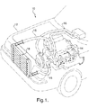
- a cooling system generally shown at 10 of a vehicle, generally shown in phantom at 12, circulates a fluid from an engine 14 through a hose 16 to a heat exchanger assembly or radiator, generally indicated at 18.
- the heat exchanger assembly 18 of the present invention includes a core 20 having first and second opposite ends 22 and 24 and opposite sides 26 and 28 for cooling the fluid flowing internally.
- the core 20 is disposed or extends between a pair of first and second header tanks 30 and 32.
- the first header tank 30 is disposed at the first end 22 of the core 20 and the second tank 32 is disposed at the second end 24 of the core 20.
- a plurality of tubes 34 through which the fluid normally flows horizontally, are disposed to extend between the first 30 and second 32 tanks, as is well known in the art.
- the ends of the tubes 34 are inserted into openings or slots 36 defined in the respective first 30 and second 32 tanks for the fluid flow therebetween.
- the first 30 and second 32 tanks also include fluid connectors 33, 35, respectively, to act as an inlet and an outlet to convey the fluid into and out of the first 30 and second 32 tanks.
- the core 20 includes a plurality of corrugated fins 40 shown in Figure 2. Each fin 40 is disposed between adjacent tubes 34 as is well known in the art. However, for simplicity, the fins 40 are not shown in the remaining Figures.
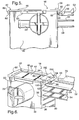
- the heat exchanger assembly 18 includes a plurality of tank caps, each generally indicated at 42.
- the tank caps 42 are configured for closing the opposite open ends of both of the first 30 and second 32 tanks at opposite terminal ends 22, 24 of the core 20.
- each tank cap 42 is disposed in engagement with the open end of the first 30 and second 32 tanks. More specifically, in order to facilitate the closure of the open ends of the first 30 and second 32 tanks, each tank cap 42 has a recess or a dished configuration with a bottom 44 and sidewalls 46 below a rim 48 for disposition in the open end of the first 30 and second 32 tanks.
- the sidewalls 46 engage the interior of the open end of each tank 30 or 32 and the rim 48 engage the open end of each tank 30, 32 for being brazed thereto.
- a pair of rectangular flanges 50 are integral with and extend outwardly in the opposite directions to the rim 48 of each tank cap 42.
- the rectangular flanges 50 are clinched or bent over and downward into the exterior of each of the first 30 and second 32 tanks.
- the core 20, the tanks 30, 32, the fins 40, the tubes 34, and the tank caps 42 consist of one homogenous material, namely a metal such as aluminum.
- a pair of a core reinforcing members extend along the opposite sides 26, 28 of the core 20.
- Each reinforcing member 52 presents terminal ends 54, 56 with each of the terminal ends 54, 56 presenting a pair of reversed interconnected first and second bends 58, 60 having an S-shaped configuration to engage the rim 48 of the adjacent tank cap 42.
- Each of the bends 58, 60 of the terminal ends 54, 56 are more narrow in width than the tank cap 42.
- a notch 62 is defined at each side of the terminal ends 54, 56 to define a bending joint between the second bend 60 at the intersection of the S-shaped configuration and the remainder of the reinforcing member 52.
- Each notch 62 assist to relieve stress applied to the core reinforcing member 52 thereby maintaining structural stability and braze clad surface contact as the heat exchanger assembly 18 is brazed.
- a gusset 64 is integral with and extends across the second bend 60 to provide structural support to each of the terminal ends 54, 56.
- Each of the core reinforcing members 52 includes a pair of spaced and parallel reinforcing flanges 70 extending upwardly and terminating short of the terminal ends 54, 56. The reinforcing flanges 70 extend upwardly along the sides of a flat bar.
- Each reinforcing member 52 consists of one homogenous material, namely a metal such as aluminum.
- the a mechanical connection for connecting each of the tank caps 42 to the adjacent terminal ends 54, 56 of the reinforcing members 52 has tabs 82 integral with and sloping outwardly and bent downwardly into an opening or cut-out portion 90 defined in each terminal end 54, 56 of the core reinforcing member 52.
- Each tab 82 has a head 84 and a neck 86 more narrow in width than the head 84.
- the neck 86 and the head 84 are interconnected by outwardly tapered sides 88 to define a dovetailed configuration of the tab 82.
- the cut-out portion 90 presents a rectangular configuration having a width complementary to the width of the neck 86 to receive the tab 82.
- the cut-out portion 90 is just wide enough to receive the neck 86 but is smaller than the head 84 to retain the tab 82 in the cut-out portion 90 for connecting or holding the core reinforcing members 52 to the tank caps 42 as the heat exchanger assembly 18 is brazed.
- the heat exchanger assembly 18 of the present invention may include an alternative embodiment that reverses the components by placing a pair of spaced tabs 190 to define a cut-out portion 192 in the tank cap 42 and a dove-tailed tab 182 extending from the terminal ends 54, 56. While only one tab 82, 182 and one complementary cut-out portion 90, 192 have been disclosed in the present invention, the number of tabs 82, 182 and complementary cut-out portions 90, 190 connecting the terminal ends 54, 56 of each reinforcing member 52 to the tank cap 42 may be more than one. In addition, the tab and /or cut-out portions may be at one or both ends of each tank cap 42.
- the aforementioned aluminum braze or brazing involves joining of components, such as, for example, the core 20 and the tanks 30, 32 prefabricated by having a brazing alloy (cladding) layer, i.e. outer layer (not shown) whose melting point is appreciably lower than that of the parent material (base alloy) base material, i.e. aluminum of the core 20 and the tanks 30, 32.
- the cladding, rolled onto the aluminum is oriented adjacent to or in between the components to be joined, like, for example, the tank cap 42 and the tanks 30 or 32, whereby the heat exchanger assembly 18 is heated to a temperature where the cladding material melts and the parent material, i.e. aluminum does not.
- the cladding Upon cooling, the cladding forms a metallurgical bond between the joining surfaces of the components, i.e. the core 20, the first 30 and second 32 header tanks, the core reinforcing members 52, and the caps 42.
- the brazing process occurs in a furnace (not shown) as is well known in the art.
- the cladding is supplied via a thin layer on the base alloy.
- the base alloy provides the structural integrity while the low melting point cladding melts to form the brazed joints.
- the core 20, the first 30 and second 32 tanks, the core reinforcing members 52, and the tank caps 42, are formed from aluminum, aluminum alloy, and the like, and are integrally brazed in the furnace to provide the heat exchanger assembly 18 having high corrosion resistance and high heat conductivity characteristics.
Landscapes
- Engineering & Computer Science (AREA)
- Physics & Mathematics (AREA)
- Thermal Sciences (AREA)
- Mechanical Engineering (AREA)
- General Engineering & Computer Science (AREA)
- Heat-Exchange Devices With Radiators And Conduit Assemblies (AREA)
- Motor Or Generator Cooling System (AREA)
Applications Claiming Priority (1)
| Application Number | Priority Date | Filing Date | Title |
|---|---|---|---|
| US10/956,889 US7395853B2 (en) | 2004-10-01 | 2004-10-01 | Heat exchanger assembly for a motor vehicle |
Publications (2)
| Publication Number | Publication Date |
|---|---|
| EP1643201A1 true EP1643201A1 (de) | 2006-04-05 |
| EP1643201B1 EP1643201B1 (de) | 2007-07-25 |
Family
ID=35717622
Family Applications (1)
| Application Number | Title | Priority Date | Filing Date |
|---|---|---|---|
| EP05077196A Not-in-force EP1643201B1 (de) | 2004-10-01 | 2005-09-27 | Wärmeaustauschvorrichtung für KFZ |
Country Status (4)
| Country | Link |
|---|---|
| US (1) | US7395853B2 (de) |
| EP (1) | EP1643201B1 (de) |
| AT (1) | ATE368207T1 (de) |
| DE (1) | DE602005001744T2 (de) |
Cited By (1)
| Publication number | Priority date | Publication date | Assignee | Title |
|---|---|---|---|---|
| WO2018167446A1 (fr) * | 2017-03-17 | 2018-09-20 | Valeo Systemes Thermiques | Radiateur à plaque d'extrémité en u orientée vers l'extérieur, et système de chauffage, ventilation ou climatisation correspondant |
Families Citing this family (12)
| Publication number | Priority date | Publication date | Assignee | Title |
|---|---|---|---|---|
| JP2007090962A (ja) * | 2005-09-27 | 2007-04-12 | Denso Corp | ラジエータ周辺部品の配置構造 |
| CN101226037A (zh) * | 2008-01-30 | 2008-07-23 | 无锡优萌汽车部件制造有限公司 | 新型汽车暖风水室的主片与边板之压合结构 |
| USD619511S1 (en) * | 2009-12-23 | 2010-07-13 | Michael Sullivan | Radiator |
| US20120024508A1 (en) * | 2010-07-28 | 2012-02-02 | Delphi Technologies, Inc. | Reinforcement plate for multiple row heat exchanger |
| USD647436S1 (en) * | 2011-03-17 | 2011-10-25 | Michael Sullivan | Radiator |
| JP5746906B2 (ja) * | 2011-04-28 | 2015-07-08 | 昭和電工株式会社 | 熱交換器 |
| DE112015002074T5 (de) | 2014-04-29 | 2017-02-23 | Dana Canada Corporation | Ladeluftkühler mit mehrteiligem Kunststoffgehäuse |
| USD717702S1 (en) * | 2014-04-29 | 2014-11-18 | Resource Intl, Inc. | Automotive radiator |
| USD717218S1 (en) * | 2014-07-24 | 2014-11-11 | Resource Intl, Inc. | Automotive radiator |
| US10704842B2 (en) | 2018-08-21 | 2020-07-07 | Denso International America, Inc. | Side plate end tab for heat exchanger |
| FR3090837B1 (fr) * | 2018-12-19 | 2021-01-15 | Valeo Systemes Thermiques | Échangeur de chaleur avec joue d’extrémité brasée |
| US11137210B2 (en) * | 2019-08-07 | 2021-10-05 | Denso International America, Inc. | Heat exchanger |
Citations (10)
| Publication number | Priority date | Publication date | Assignee | Title |
|---|---|---|---|---|
| FR2735855A1 (fr) * | 1995-06-23 | 1996-12-27 | Valeo Climatisation | Procede d'assemblage d'un sous-ensemble d'echangeur de chaleur |
| JPH09126685A (ja) * | 1995-10-31 | 1997-05-16 | Denso Corp | 熱交換器 |
| EP1030157A1 (de) * | 1997-11-14 | 2000-08-23 | Zexel Corporation | Wärmetauscher |
| JP2000283691A (ja) * | 1999-03-30 | 2000-10-13 | Toyo Radiator Co Ltd | 熱交換器 |
| JP2003139484A (ja) * | 2001-10-30 | 2003-05-14 | Denso Corp | 積層型熱交換器 |
| WO2005001370A1 (ja) * | 2003-06-26 | 2005-01-06 | Toyo Radiator Co., Ltd. | アルミニウム製ラジエータ |
| EP1500892A2 (de) * | 2003-07-22 | 2005-01-26 | Modine Manufacturing Company | Wärmeaustauscher für Kraftfahrzeuge |
| DE10343634A1 (de) * | 2003-09-20 | 2005-04-14 | Modine Manufacturing Co., Racine | Wärmeaustauscher für Kraftfahrzeuge |
| EP1528347A2 (de) * | 2003-10-29 | 2005-05-04 | Delphi Technologies, Inc. | Verschluss mit integriertiem Stromumlenker |
| EP1553373A2 (de) * | 2004-01-08 | 2005-07-13 | Delphi Technologies, Inc. | Einteiliger verstärkterter Seitenteil mit winkligem Endverschluss zu vereinfachten Montage zum Wärmetauscherkörper |
Family Cites Families (23)
| Publication number | Priority date | Publication date | Assignee | Title |
|---|---|---|---|---|
| US4406132A (en) * | 1980-05-19 | 1983-09-27 | Carrier Corporation | Method for assembling an air conditioning unit including a tube sheet isolator |
| FR2507760B1 (fr) * | 1981-06-12 | 1986-05-02 | Valeo | Dispositif de fixation d'un echangeur de chaleur dans un boitier et installation de chauffage ou de climatisation de vehicule automobile |
| EP0102715A3 (de) | 1982-09-03 | 1984-08-01 | Unipart Group Limited | Wärmetauscher |
| JPH01114697A (ja) * | 1987-10-29 | 1989-05-08 | Nippon Denso Co Ltd | 熱交換器 |
| JPH0240495A (ja) * | 1988-08-01 | 1990-02-09 | Nippon Denso Co Ltd | 熱交換器 |
| JP2968063B2 (ja) | 1991-02-20 | 1999-10-25 | サンデン株式会社 | 熱交換器 |
| JPH0560485A (ja) * | 1992-02-24 | 1993-03-09 | Nippondenso Co Ltd | 冷媒凝縮器 |
| US5289873A (en) | 1992-06-22 | 1994-03-01 | General Motors Corporation | Heat exchanger sideplate interlocked with header |
| US5542176A (en) * | 1992-09-21 | 1996-08-06 | Hideaki Serizawa | Radiation plate and method of producing the same |
| JP3393957B2 (ja) * | 1995-05-30 | 2003-04-07 | サンデン株式会社 | 熱交換器の流体給排管接合方法 |
| JP3677898B2 (ja) * | 1996-10-22 | 2005-08-03 | 株式会社デンソー | 複式熱交換器 |
| JPH10332293A (ja) | 1997-06-02 | 1998-12-15 | Mitsubishi Heavy Ind Ltd | 熱交換器 |
| WO2000022366A1 (en) * | 1998-10-09 | 2000-04-20 | S.C. Romradiatoare S.A. | High efficiency heat exchanger with oval tubes |
| JP4281175B2 (ja) * | 1999-09-29 | 2009-06-17 | 株式会社デンソー | 複式熱交換器 |
| US6179050B1 (en) | 1999-09-29 | 2001-01-30 | Valeo Thermique Moteur | Heat exchangers |
| JP2002081884A (ja) * | 2000-09-07 | 2002-03-22 | Denso Corp | 熱交換器の取付構造 |
| JP3728534B2 (ja) * | 2001-04-09 | 2005-12-21 | 漢拏空調株式会社 | アルミニウムラジエータ |
| JP2002350086A (ja) * | 2001-05-23 | 2002-12-04 | Denso Corp | 熱交換器 |
| US6529377B1 (en) * | 2001-09-05 | 2003-03-04 | Microelectronic & Computer Technology Corporation | Integrated cooling system |
| US20030159816A1 (en) | 2002-02-22 | 2003-08-28 | Valeo Inc. | Heat exchanger apparatus with integrated supply/return tube |
| US6829814B1 (en) * | 2002-08-29 | 2004-12-14 | Delphi Technologies, Inc. | Process of making an all-silicon microphone |
| US20050230089A1 (en) * | 2004-04-05 | 2005-10-20 | Denso Corporation | Heat exchanger capable of preventing heat stress |
| CN2701074Y (zh) * | 2004-04-29 | 2005-05-18 | 鸿富锦精密工业(深圳)有限公司 | 液冷散热装置 |
-
2004
- 2004-10-01 US US10/956,889 patent/US7395853B2/en not_active Expired - Fee Related
-
2005
- 2005-09-27 DE DE602005001744T patent/DE602005001744T2/de active Active
- 2005-09-27 AT AT05077196T patent/ATE368207T1/de not_active IP Right Cessation
- 2005-09-27 EP EP05077196A patent/EP1643201B1/de not_active Not-in-force
Patent Citations (10)
| Publication number | Priority date | Publication date | Assignee | Title |
|---|---|---|---|---|
| FR2735855A1 (fr) * | 1995-06-23 | 1996-12-27 | Valeo Climatisation | Procede d'assemblage d'un sous-ensemble d'echangeur de chaleur |
| JPH09126685A (ja) * | 1995-10-31 | 1997-05-16 | Denso Corp | 熱交換器 |
| EP1030157A1 (de) * | 1997-11-14 | 2000-08-23 | Zexel Corporation | Wärmetauscher |
| JP2000283691A (ja) * | 1999-03-30 | 2000-10-13 | Toyo Radiator Co Ltd | 熱交換器 |
| JP2003139484A (ja) * | 2001-10-30 | 2003-05-14 | Denso Corp | 積層型熱交換器 |
| WO2005001370A1 (ja) * | 2003-06-26 | 2005-01-06 | Toyo Radiator Co., Ltd. | アルミニウム製ラジエータ |
| EP1500892A2 (de) * | 2003-07-22 | 2005-01-26 | Modine Manufacturing Company | Wärmeaustauscher für Kraftfahrzeuge |
| DE10343634A1 (de) * | 2003-09-20 | 2005-04-14 | Modine Manufacturing Co., Racine | Wärmeaustauscher für Kraftfahrzeuge |
| EP1528347A2 (de) * | 2003-10-29 | 2005-05-04 | Delphi Technologies, Inc. | Verschluss mit integriertiem Stromumlenker |
| EP1553373A2 (de) * | 2004-01-08 | 2005-07-13 | Delphi Technologies, Inc. | Einteiliger verstärkterter Seitenteil mit winkligem Endverschluss zu vereinfachten Montage zum Wärmetauscherkörper |
Non-Patent Citations (3)
| Title |
|---|
| PATENT ABSTRACTS OF JAPAN vol. 1997, no. 09 30 September 1997 (1997-09-30) * |
| PATENT ABSTRACTS OF JAPAN vol. 2000, no. 13 5 February 2001 (2001-02-05) * |
| PATENT ABSTRACTS OF JAPAN vol. 2003, no. 09 3 September 2003 (2003-09-03) * |
Cited By (4)
| Publication number | Priority date | Publication date | Assignee | Title |
|---|---|---|---|---|
| WO2018167446A1 (fr) * | 2017-03-17 | 2018-09-20 | Valeo Systemes Thermiques | Radiateur à plaque d'extrémité en u orientée vers l'extérieur, et système de chauffage, ventilation ou climatisation correspondant |
| FR3064054A1 (fr) * | 2017-03-17 | 2018-09-21 | Valeo Systemes Thermiques | Radiateur a plaque d’extremite en u orientee vers l’exterieur, et systeme de chauffage, ventilation ou climatisation correspondant |
| CN110431372A (zh) * | 2017-03-17 | 2019-11-08 | 法雷奥热系统公司 | 包括向外的u形端板的散热器以及相应的供暖、通风或空调系统 |
| CN110431372B (zh) * | 2017-03-17 | 2022-09-27 | 法雷奥热系统公司 | 包括向外的u形端板的散热器以及相应的供暖、通风或空调系统 |
Also Published As
| Publication number | Publication date |
|---|---|
| US20060070725A1 (en) | 2006-04-06 |
| EP1643201B1 (de) | 2007-07-25 |
| ATE368207T1 (de) | 2007-08-15 |
| DE602005001744D1 (de) | 2007-09-06 |
| US7395853B2 (en) | 2008-07-08 |
| DE602005001744T2 (de) | 2008-04-30 |
Similar Documents
| Publication | Publication Date | Title |
|---|---|---|
| US7461685B2 (en) | Heat exchanger | |
| US7395853B2 (en) | Heat exchanger assembly for a motor vehicle | |
| EP0641986B1 (de) | Wärmetauscher und Verfahren zu seiner Herstellung | |
| AU679783B2 (en) | Aluminum heat exchanger | |
| US7461689B2 (en) | Thermal cycling resistant tube to header joint for heat exchangers | |
| EP1030157B1 (de) | Wärmetauscher | |
| US5678628A (en) | Heat exchanger and method for manufacturing the same | |
| JP2001194080A (ja) | 熱交換器 | |
| JP2000234883A (ja) | 熱交換器 | |
| JPH10206071A (ja) | 熱交換器用タンク | |
| EP0798530A1 (de) | Wärmetauscher | |
| JPH10238987A (ja) | 熱交換器 | |
| JP4866571B2 (ja) | 熱交換器 | |
| JP2750167B2 (ja) | 熱交換器 | |
| JP2003106791A (ja) | 熱交換器 | |
| EP1004841B1 (de) | Wasserkasten für Wärmetauscher | |
| JPH0886590A (ja) | 一体型熱交換器用タンク | |
| JP3207317B2 (ja) | アルミニウム合金製熱交換器 | |
| JP2002181480A (ja) | 熱交換器 | |
| JP3517230B2 (ja) | 熱交換器のパイプ組付構造 | |
| EP0881008A2 (de) | Verfahren zur Herstellung von Kühlröhren für Wärmetauscher | |
| CN112739972A (zh) | 用于散热器应用的顺应性b型管 | |
| JP4412770B2 (ja) | 熱交換器 | |
| JP3209856B2 (ja) | アルミニウム材製熱交換器の製造方法 | |
| JP2007010176A (ja) | 熱交換器 |
Legal Events
| Date | Code | Title | Description |
|---|---|---|---|
| PUAI | Public reference made under article 153(3) epc to a published international application that has entered the european phase |
Free format text: ORIGINAL CODE: 0009012 |
|
| AK | Designated contracting states |
Kind code of ref document: A1 Designated state(s): AT BE BG CH CY CZ DE DK EE ES FI FR GB GR HU IE IS IT LI LT LU LV MC NL PL PT RO SE SI SK TR |
|
| AX | Request for extension of the european patent |
Extension state: AL BA HR MK YU |
|
| 17P | Request for examination filed |
Effective date: 20061005 |
|
| 17Q | First examination report despatched |
Effective date: 20061107 |
|
| AKX | Designation fees paid |
Designated state(s): AT BE BG CH CY CZ DE DK EE ES FI FR GB GR HU IE IS IT LI LT LU LV MC NL PL PT RO SE SI SK TR |
|
| GRAP | Despatch of communication of intention to grant a patent |
Free format text: ORIGINAL CODE: EPIDOSNIGR1 |
|
| GRAS | Grant fee paid |
Free format text: ORIGINAL CODE: EPIDOSNIGR3 |
|
| GRAA | (expected) grant |
Free format text: ORIGINAL CODE: 0009210 |
|
| AK | Designated contracting states |
Kind code of ref document: B1 Designated state(s): AT BE BG CH CY CZ DE DK EE ES FI FR GB GR HU IE IS IT LI LT LU LV MC NL PL PT RO SE SI SK TR |
|
| REG | Reference to a national code |
Ref country code: GB Ref legal event code: FG4D |
|
| REG | Reference to a national code |
Ref country code: CH Ref legal event code: EP |
|
| REG | Reference to a national code |
Ref country code: IE Ref legal event code: FG4D |
|
| REF | Corresponds to: |
Ref document number: 602005001744 Country of ref document: DE Date of ref document: 20070906 Kind code of ref document: P |
|
| ET | Fr: translation filed | ||
| PG25 | Lapsed in a contracting state [announced via postgrant information from national office to epo] |
Ref country code: ES Free format text: LAPSE BECAUSE OF FAILURE TO SUBMIT A TRANSLATION OF THE DESCRIPTION OR TO PAY THE FEE WITHIN THE PRESCRIBED TIME-LIMIT Effective date: 20071105 Ref country code: PT Free format text: LAPSE BECAUSE OF FAILURE TO SUBMIT A TRANSLATION OF THE DESCRIPTION OR TO PAY THE FEE WITHIN THE PRESCRIBED TIME-LIMIT Effective date: 20071226 Ref country code: IS Free format text: LAPSE BECAUSE OF FAILURE TO SUBMIT A TRANSLATION OF THE DESCRIPTION OR TO PAY THE FEE WITHIN THE PRESCRIBED TIME-LIMIT Effective date: 20071125 Ref country code: FI Free format text: LAPSE BECAUSE OF FAILURE TO SUBMIT A TRANSLATION OF THE DESCRIPTION OR TO PAY THE FEE WITHIN THE PRESCRIBED TIME-LIMIT Effective date: 20070725 Ref country code: LT Free format text: LAPSE BECAUSE OF FAILURE TO SUBMIT A TRANSLATION OF THE DESCRIPTION OR TO PAY THE FEE WITHIN THE PRESCRIBED TIME-LIMIT Effective date: 20070725 Ref country code: NL Free format text: LAPSE BECAUSE OF FAILURE TO SUBMIT A TRANSLATION OF THE DESCRIPTION OR TO PAY THE FEE WITHIN THE PRESCRIBED TIME-LIMIT Effective date: 20070725 Ref country code: BG Free format text: LAPSE BECAUSE OF FAILURE TO SUBMIT A TRANSLATION OF THE DESCRIPTION OR TO PAY THE FEE WITHIN THE PRESCRIBED TIME-LIMIT Effective date: 20071025 |
|
| REG | Reference to a national code |
Ref country code: CH Ref legal event code: PL |
|
| NLV1 | Nl: lapsed or annulled due to failure to fulfill the requirements of art. 29p and 29m of the patents act | ||
| PG25 | Lapsed in a contracting state [announced via postgrant information from national office to epo] |
Ref country code: PL Free format text: LAPSE BECAUSE OF FAILURE TO SUBMIT A TRANSLATION OF THE DESCRIPTION OR TO PAY THE FEE WITHIN THE PRESCRIBED TIME-LIMIT Effective date: 20070725 Ref country code: LI Free format text: LAPSE BECAUSE OF FAILURE TO SUBMIT A TRANSLATION OF THE DESCRIPTION OR TO PAY THE FEE WITHIN THE PRESCRIBED TIME-LIMIT Effective date: 20070725 Ref country code: AT Free format text: LAPSE BECAUSE OF FAILURE TO SUBMIT A TRANSLATION OF THE DESCRIPTION OR TO PAY THE FEE WITHIN THE PRESCRIBED TIME-LIMIT Effective date: 20070725 Ref country code: CH Free format text: LAPSE BECAUSE OF FAILURE TO SUBMIT A TRANSLATION OF THE DESCRIPTION OR TO PAY THE FEE WITHIN THE PRESCRIBED TIME-LIMIT Effective date: 20070725 |
|
| PG25 | Lapsed in a contracting state [announced via postgrant information from national office to epo] |
Ref country code: BE Free format text: LAPSE BECAUSE OF FAILURE TO SUBMIT A TRANSLATION OF THE DESCRIPTION OR TO PAY THE FEE WITHIN THE PRESCRIBED TIME-LIMIT Effective date: 20070725 Ref country code: LV Free format text: LAPSE BECAUSE OF FAILURE TO SUBMIT A TRANSLATION OF THE DESCRIPTION OR TO PAY THE FEE WITHIN THE PRESCRIBED TIME-LIMIT Effective date: 20070725 |
|
| PG25 | Lapsed in a contracting state [announced via postgrant information from national office to epo] |
Ref country code: DK Free format text: LAPSE BECAUSE OF FAILURE TO SUBMIT A TRANSLATION OF THE DESCRIPTION OR TO PAY THE FEE WITHIN THE PRESCRIBED TIME-LIMIT Effective date: 20070725 Ref country code: MC Free format text: LAPSE BECAUSE OF NON-PAYMENT OF DUE FEES Effective date: 20070930 Ref country code: GR Free format text: LAPSE BECAUSE OF FAILURE TO SUBMIT A TRANSLATION OF THE DESCRIPTION OR TO PAY THE FEE WITHIN THE PRESCRIBED TIME-LIMIT Effective date: 20071026 |
|
| PG25 | Lapsed in a contracting state [announced via postgrant information from national office to epo] |
Ref country code: CZ Free format text: LAPSE BECAUSE OF FAILURE TO SUBMIT A TRANSLATION OF THE DESCRIPTION OR TO PAY THE FEE WITHIN THE PRESCRIBED TIME-LIMIT Effective date: 20070725 Ref country code: SK Free format text: LAPSE BECAUSE OF FAILURE TO SUBMIT A TRANSLATION OF THE DESCRIPTION OR TO PAY THE FEE WITHIN THE PRESCRIBED TIME-LIMIT Effective date: 20070725 |
|
| PLBE | No opposition filed within time limit |
Free format text: ORIGINAL CODE: 0009261 |
|
| STAA | Information on the status of an ep patent application or granted ep patent |
Free format text: STATUS: NO OPPOSITION FILED WITHIN TIME LIMIT |
|
| PG25 | Lapsed in a contracting state [announced via postgrant information from national office to epo] |
Ref country code: RO Free format text: LAPSE BECAUSE OF FAILURE TO SUBMIT A TRANSLATION OF THE DESCRIPTION OR TO PAY THE FEE WITHIN THE PRESCRIBED TIME-LIMIT Effective date: 20070725 Ref country code: SE Free format text: LAPSE BECAUSE OF FAILURE TO SUBMIT A TRANSLATION OF THE DESCRIPTION OR TO PAY THE FEE WITHIN THE PRESCRIBED TIME-LIMIT Effective date: 20071025 |
|
| 26N | No opposition filed |
Effective date: 20080428 |
|
| PG25 | Lapsed in a contracting state [announced via postgrant information from national office to epo] |
Ref country code: IE Free format text: LAPSE BECAUSE OF NON-PAYMENT OF DUE FEES Effective date: 20070927 |
|
| PG25 | Lapsed in a contracting state [announced via postgrant information from national office to epo] |
Ref country code: EE Free format text: LAPSE BECAUSE OF FAILURE TO SUBMIT A TRANSLATION OF THE DESCRIPTION OR TO PAY THE FEE WITHIN THE PRESCRIBED TIME-LIMIT Effective date: 20070725 |
|
| PG25 | Lapsed in a contracting state [announced via postgrant information from national office to epo] |
Ref country code: SI Free format text: LAPSE BECAUSE OF FAILURE TO SUBMIT A TRANSLATION OF THE DESCRIPTION OR TO PAY THE FEE WITHIN THE PRESCRIBED TIME-LIMIT Effective date: 20070725 |
|
| PG25 | Lapsed in a contracting state [announced via postgrant information from national office to epo] |
Ref country code: CY Free format text: LAPSE BECAUSE OF FAILURE TO SUBMIT A TRANSLATION OF THE DESCRIPTION OR TO PAY THE FEE WITHIN THE PRESCRIBED TIME-LIMIT Effective date: 20070725 |
|
| PG25 | Lapsed in a contracting state [announced via postgrant information from national office to epo] |
Ref country code: LU Free format text: LAPSE BECAUSE OF NON-PAYMENT OF DUE FEES Effective date: 20070927 |
|
| PG25 | Lapsed in a contracting state [announced via postgrant information from national office to epo] |
Ref country code: TR Free format text: LAPSE BECAUSE OF FAILURE TO SUBMIT A TRANSLATION OF THE DESCRIPTION OR TO PAY THE FEE WITHIN THE PRESCRIBED TIME-LIMIT Effective date: 20070725 Ref country code: HU Free format text: LAPSE BECAUSE OF FAILURE TO SUBMIT A TRANSLATION OF THE DESCRIPTION OR TO PAY THE FEE WITHIN THE PRESCRIBED TIME-LIMIT Effective date: 20080126 |
|
| GBPC | Gb: european patent ceased through non-payment of renewal fee |
Effective date: 20090927 |
|
| PG25 | Lapsed in a contracting state [announced via postgrant information from national office to epo] |
Ref country code: GB Free format text: LAPSE BECAUSE OF NON-PAYMENT OF DUE FEES Effective date: 20070725 |
|
| PG25 | Lapsed in a contracting state [announced via postgrant information from national office to epo] |
Ref country code: IT Free format text: LAPSE BECAUSE OF NON-PAYMENT OF DUE FEES Effective date: 20070930 |
|
| REG | Reference to a national code |
Ref country code: FR Ref legal event code: PLFP Year of fee payment: 11 |
|
| REG | Reference to a national code |
Ref country code: DE Ref legal event code: R082 Ref document number: 602005001744 Country of ref document: DE Representative=s name: BRP RENAUD UND PARTNER MBB, DE Ref country code: DE Ref legal event code: R081 Ref document number: 602005001744 Country of ref document: DE Owner name: MAHLE INTERNATIONAL GMBH, DE Free format text: FORMER OWNER: DELPHI TECHNOLOGIES, INC., TROY, MICH., US Ref country code: DE Ref legal event code: R082 Ref document number: 602005001744 Country of ref document: DE Representative=s name: BRP RENAUD UND PARTNER MBB RECHTSANWAELTE PATE, DE |
|
| REG | Reference to a national code |
Ref country code: FR Ref legal event code: PLFP Year of fee payment: 12 |
|
| REG | Reference to a national code |
Ref country code: FR Ref legal event code: PLFP Year of fee payment: 13 |
|
| REG | Reference to a national code |
Ref country code: FR Ref legal event code: TP Owner name: MAHLE INTERNATIONAL GMBH, DE Effective date: 20180103 |
|
| REG | Reference to a national code |
Ref country code: FR Ref legal event code: PLFP Year of fee payment: 14 |
|
| PGFP | Annual fee paid to national office [announced via postgrant information from national office to epo] |
Ref country code: FR Payment date: 20180928 Year of fee payment: 14 |
|
| PGFP | Annual fee paid to national office [announced via postgrant information from national office to epo] |
Ref country code: DE Payment date: 20181130 Year of fee payment: 14 |
|
| REG | Reference to a national code |
Ref country code: DE Ref legal event code: R119 Ref document number: 602005001744 Country of ref document: DE |
|
| PG25 | Lapsed in a contracting state [announced via postgrant information from national office to epo] |
Ref country code: DE Free format text: LAPSE BECAUSE OF NON-PAYMENT OF DUE FEES Effective date: 20200401 |
|
| PG25 | Lapsed in a contracting state [announced via postgrant information from national office to epo] |
Ref country code: FR Free format text: LAPSE BECAUSE OF NON-PAYMENT OF DUE FEES Effective date: 20190930 |