EP1643295A1 - Filtre acoustico-optique - Google Patents
Filtre acoustico-optique Download PDFInfo
- Publication number
- EP1643295A1 EP1643295A1 EP04728935A EP04728935A EP1643295A1 EP 1643295 A1 EP1643295 A1 EP 1643295A1 EP 04728935 A EP04728935 A EP 04728935A EP 04728935 A EP04728935 A EP 04728935A EP 1643295 A1 EP1643295 A1 EP 1643295A1
- Authority
- EP
- European Patent Office
- Prior art keywords
- acoustooptic
- filter according
- changing
- waveguide
- acoustooptic filter
- Prior art date
- Legal status (The legal status is an assumption and is not a legal conclusion. Google has not performed a legal analysis and makes no representation as to the accuracy of the status listed.)
- Withdrawn
Links
Images





Classifications
-
- G—PHYSICS
- G02—OPTICS
- G02F—OPTICAL DEVICES OR ARRANGEMENTS FOR THE CONTROL OF LIGHT BY MODIFICATION OF THE OPTICAL PROPERTIES OF THE MEDIA OF THE ELEMENTS INVOLVED THEREIN; NON-LINEAR OPTICS; FREQUENCY-CHANGING OF LIGHT; OPTICAL LOGIC ELEMENTS; OPTICAL ANALOGUE/DIGITAL CONVERTERS
- G02F1/00—Devices or arrangements for the control of the intensity, colour, phase, polarisation or direction of light arriving from an independent light source, e.g. switching, gating or modulating; Non-linear optics
- G02F1/01—Devices or arrangements for the control of the intensity, colour, phase, polarisation or direction of light arriving from an independent light source, e.g. switching, gating or modulating; Non-linear optics for the control of the intensity, phase, polarisation or colour
- G02F1/11—Devices or arrangements for the control of the intensity, colour, phase, polarisation or direction of light arriving from an independent light source, e.g. switching, gating or modulating; Non-linear optics for the control of the intensity, phase, polarisation or colour based on acousto-optical elements, e.g. using variable diffraction by sound or like mechanical waves
- G02F1/125—Devices or arrangements for the control of the intensity, colour, phase, polarisation or direction of light arriving from an independent light source, e.g. switching, gating or modulating; Non-linear optics for the control of the intensity, phase, polarisation or colour based on acousto-optical elements, e.g. using variable diffraction by sound or like mechanical waves in an optical waveguide structure
-
- G—PHYSICS
- G02—OPTICS
- G02F—OPTICAL DEVICES OR ARRANGEMENTS FOR THE CONTROL OF LIGHT BY MODIFICATION OF THE OPTICAL PROPERTIES OF THE MEDIA OF THE ELEMENTS INVOLVED THEREIN; NON-LINEAR OPTICS; FREQUENCY-CHANGING OF LIGHT; OPTICAL LOGIC ELEMENTS; OPTICAL ANALOGUE/DIGITAL CONVERTERS
- G02F1/00—Devices or arrangements for the control of the intensity, colour, phase, polarisation or direction of light arriving from an independent light source, e.g. switching, gating or modulating; Non-linear optics
- G02F1/01—Devices or arrangements for the control of the intensity, colour, phase, polarisation or direction of light arriving from an independent light source, e.g. switching, gating or modulating; Non-linear optics for the control of the intensity, phase, polarisation or colour
- G02F1/11—Devices or arrangements for the control of the intensity, colour, phase, polarisation or direction of light arriving from an independent light source, e.g. switching, gating or modulating; Non-linear optics for the control of the intensity, phase, polarisation or colour based on acousto-optical elements, e.g. using variable diffraction by sound or like mechanical waves
Definitions
- the present invention relates to an acoustooptic filter in which an interdigital electrode for exciting a surface wave is formed on an acoustooptic filter substrate having an optical waveguide formed thereat, and, more particularly, to an acoustooptic filter in which a mutual action area where light and a surface acoustic wave act upon each other is improved.
- optical communication systems which can perform communications at high capacity have become in widespread use, not only for data traffic, but also even for access traffic.
- optical transmission is speeded up and optical wavelength division multiplexing is achieved.
- a light wavelength filter is available as an important component for realizing wavelength division multiplexing.
- the light wavelength filter filters light of a particular wavelength, and is an important component for performing optical wavelength division multiplex communication.
- a light wavelength filter shown in Fig. 12 is disclosed in "Low Drive-Power Integrated Acoustooptic Filter On X-cut Y-propagating LiNbO 3 ,” IEEEPHOTONICS TECHNOLOGY LETTERS, Vol. 3, No. 10, 1991.
- a light wavelength filter 101 an optical waveguide 103 in which Ti is diffused is formed at an X-cut Y-propagating LiNbO 3 substrate 102.
- IDTs 104 and 105 are disposed on the LiNbO 3 substrate 102.
- walls 106 and 107 in which Ti is diffused are disposed, one on each side of a surface acoustic wave propagation area.
- a light wavelength filter having a narrow band at low electrical power is formed by forming the walls 106 and 107.
- a light wavelength filter shown in Fig. 13 is disclosed in "LiNbO 3 Tunable Wavelength Filter Using Acoustooptic Effect" (Year 200 Commemoration of Advanced Technology Symposium, “Piezoelectric Materials and Acoustic Wave Devices," February, 2000).
- a light wavelength filter 111 an optical waveguide 113 in which Ti is diffused is formed at an X-cut Y-propagating LiNbO 3 substrate 112.
- an IDT 114 is provided for exciting a surface wave.
- a film-addition-type guide 115 is formed. Accordingly, a light wavelength filter capable of being integrated and having a narrow band is realized.
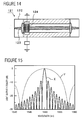
- a light wavelength filter shown in Fig. 14 is disclosed in Japanese Unexamined Patent Application Publication No. 11-84331.
- a light wavelength filter 121 an optical waveguide 123 and an IDT 124 are formed at a substrate 122.
- a birefringence distribution generated in the light wavelength filter 121 is compensated, thereby making it possible to restrict an increase in side lobe in a frequency characteristic.
- an interval between light wavelengths that are multiplexed and the number of multiplexing operations vary depending upon optical communication systems.
- standards of, for example, CWDM (Coarse WDM) have been proposed.
- CWDM is for realizing a low-cost system by increasing the interval between wavelengths that are multiplexed. Therefore, in CWDM, there is a strong demand that the light wavelength filter have a flat characteristic over a broad band.
- a phase match condition in the mutual action area is made constant by compensating the birefringence distribution existing in the light wavelength filter as a result of changing the birefringence of the optical waveguide.
- the mutual action area length must be short.
- a wavelength transmission characteristic (indicated by a solid line X in Fig. 15) when a phase condition in the mutual action area is constant becomes a characteristic indicated by a broken line L shown in Fig. 15 when the band of this filter is widened by a factor of 10.
- Figs. 16 and 17 show changes in the filter band with respect to the mutual action area length and changes in a required input electrical power with respect to the mutual action area length, respectively.
- the mutual action area length, the input electrical power, and the transmission band are standardized as 1 when the characteristic shown by the solid line X in Fig. 15 is set.
- the mutual action area length is reduced to 1/10 of the length before widening the band, and the required input electrical power is increased by a factor of 100.
- the light wavelength filter of the related art disclosed in Japanese Unexamined Patent Application Publication No. 11-84331 cannot provide a flat wavelength transmission characteristic over a broad band and at low electrical power.
- An object of the present invention is to provide an acoustooptic filter which can provide a flat wavelength transmission characteristic over a broad band and at low electrical power by overcoming the problems of the aforementioned related art.
- the present invention provides an acoustooptic filter comprising an acoustooptic substrate having an optical waveguide disposed at a principal surface, an interdigital electrode disposed on the acoustooptic substrate and exciting a surface acoustic wave for converting a mode of light guided in the optical waveguide, with a surface wave waveguide for the surface wave excited by the interdigital electrode extending in substantially the same direction as the optical waveguide and the mode of the light guided to the optical waveguide being converted by the surface acoustic wave, and phase match condition changing means for changing a phase match condition at a mutual action area by 0.235% or more from a state in which phases are matched, the mutual action area being an area where the surface acoustic wave and the light guided to the optical waveguide act upon each other.
- the phase match condition changing means is means for changing the phase speed of the surface acoustic wave at the mutual action area.
- the phase match condition changing means is means for changing the phase speed of the surface acoustic wave at the surface wave waveguide.
- the means for changing the phase speed of the surface acoustic wave at the surface wave waveguide is a thin-film ridge disposed at the surface wave waveguide.
- the thickness of the thin-film ridge changes along the surface wave waveguide, so that the phase speed of the surface acoustic wave is changed at the surface wave waveguide.
- the means for changing the phase speed of the surface wave at the surface wave waveguide has a structure in which the width of the surface wave waveguide changes in the direction of extension of the surface wave waveguide.
- a pair of wall surfaces for reflecting the surface wave are disposed, one at each side of the surface wave waveguide, and the phase speed at the surface wave waveguide is changed by the pair of wall surfaces.
- structures of wall members having the respective wall surfaces change along the surface wave waveguide, so that the phase speed of the surface acoustic wave is changed.
- the distance between the pair of wall surfaces changes, so that the width of the surface wave waveguide changes.
- the phase match condition changing means is a phase speed control film for changing the phase speed of the surface acoustic wave at the mutual action area.
- the thickness of the phase speed control film is selected so that the phase match condition changes by 0.235% or more.
- the phase match condition changing means is means for changing a propagation coefficient of the surface acoustic wave or an effective refractive index of the light at the mutual action area.
- the means for changing a propagation coefficient of the surface acoustic wave or an effective refractive index of the light is means for setting a temperature distribution of the mutual action area.
- the temperature distribution setting means is a heating element disposed on the acoustooptic substrate.
- the heating element is a heater.
- the interdigital electrode is the heating element.
- the temperature distribution setting means is formed of a thin film disposed on the surface wave waveguide, and the thickness of the thin film partly differs so as to possess the temperature distribution.
- the means for changing a propagation coefficient of the surface wave or an effective refractive index of the light at the mutual action area is disposed at the optical waveguide.
- the means for changing a propagation coefficient or an effective refractive index of the light is the optical waveguide having a width which is set so as to change the phase match condition by 0.235% or more.
- the means for changing a propagation coefficient or an effective refractive index of the light, which is disposed at the optical waveguide is formed of metal diffused at the optical waveguide.
- Fig. 1(a) is a perspective view of an acoustooptic filter according a first embodiment of the present invention
- Fig. 1(b) is a schematic sectional view taken along line A-A shown in Fig. 1(a).
- An acoustooptic filter 1 has an X-cut Y-propagating LiNbO 3 piezoelectric substrate 2.
- An optical waveguide 3 is formed in a widthwise-direction central portion of an upper surface 2a of the piezoelectric substrate 1 so as to extend longitudinally.
- the optical waveguide 3 is formed by thermally diffusing Ti.
- the optical waveguide 3 is formed in an area having a width of 90 nm at the central portion of the upper surface 2a of the piezoelectric substrate 2 by thermally diffusing Ti for 8 hours at a temperature of 1040°C.
- the optical waveguide 3 is formed over the entire longitudinal-direction length at the upper surface 2a of the piezoelectric substrate 2.
- the length of the piezoelectric substrate 2 is 60 mm, and its width is 5 mm.
- An interdigital electrode IDT 4 for exciting a surface acoustic wave is formed on the upper surface of the piezoelectric substrate 2.
- the IDT 4 is formed so that the wavelength is 20 ⁇ m, the electrode finger crossing width is 60 ⁇ m, and the center frequency is from 170 to 180 MHz.
- a thin-film ridge 5 is formed in a mutual action area of the piezoelectric substrate 2.
- the mutual action area is an area where light guided to the optical waveguide 3 and a surface wave act upon each other. In the embodiment, this area extends from where the IDT 4 is disposed to an end face 2b of the piezoelectric substrate 2.
- the thin-film ridge 5 is formed by sputtering ZnO.
- the thin-film ridge 5 has a length of 30 mm and a width of 50 ⁇ m. As is clear from Fig. 1, the film thickness increases with increasing distance from an end 5a adjacent to the IDT 4. More specifically, the film thickness of the thin-film ridge 5 is 0.4 ⁇ m at the end 5a adjacent to the IDT 4 and is 1.0 ⁇ m at an opposite end 5b.
- An absorbent 6 is disposed outwardly of the IDT 4.
- Another absorbent 7 is disposed at an outer end portion of the mutual action area.
- the absorbents 6 and 7 are formed of silicone rubber.
- the absorbents 6 and 7 may be formed of, for example, polyimide or epoxy.
- a characteristic of the acoustooptic filter 1 according to the embodiment is that the film thickness of the thin-film ridge 5 changes from the end 5a to the end 5b, so that a mutual match condition in the mutual action area changes by approximately 1% from a state in which phases are matched. Therefore, a light transmission band is widened by a factor of approximately 30 without reducing the length of the mutual action area. This will be explained with reference to Figs. 2 to 4.
- the acoustooptic filter is a device which performs conversion between a light TE mode and a light TM mode.
- the wavelength of light is ⁇
- the propagation coefficients of the TE mode and the TM mode are ⁇ a and ⁇ b
- the effective refractive indices are Na and Nb
- the phase speed of a surface acoustic wave is ⁇
- the phase match condition is represented by the following Formula (1):
- 2 ⁇ ⁇
- 2 ⁇ ⁇
- the width of the light transmission band is determined by the mutual action area length. Changing the phase match condition within the mutual action area length makes it possible to widen the light transmission band regardless of the mutual action area length. Therefore, it can be understood that the mutual action area can be long, and that the light transmission band can be wide at low electrical power.
- Examples of means for changing such a phase match condition include means for changing the phase speed of a surface acoustic wave in the mutual action area and means for changing the propagation coefficient of the surface acoustic wave or the effective refractive index of light.
- the phase speed of the surface acoustic wave is changed by the thin-film ridge 5, so that the phase match condition changes by approximately 1%.
- Fig. 2 is a graph showing the relationship between a standardized transmission band and a standardized input electric power.
- the broken line in Fig. 2 indicates a case in which the phase match condition is constant, while the solid line in Fig. 2 indicates a case in which the phase match condition changes.
- the bandwidth changes on the basis of the mutual action area length.
- the mutual action area length must be reduced to 1/10 of the length before increasing the bandwidth.
- the input electrical power is increased by a factor of 100 as shown in Fig. 2.
- the input electrical power is increased by a factor of 10 (refer to Fig. 2)
- the required input electrical power is reduced to 1/10 of the required input electrical power of the case in which the phase match condition is constant.
- the required electrical power of the structure in which the phase match condition changes is half of that of the structure in which the phase match condition is constant.
- Fig. 3 is a graph showing characteristics of the acoustooptic filter according to the present invention when the phase match condition is changed by 0.7% and by 1.1% and the band is widened by a factor of 10 in comparison with the transmission band characteristics shown in Fig. 15. As shown in Fig. 3, changing the phase match condition by 0.7% can widen the band shown by the solid line in Fig. 15 by a factor of 10, and changing the phase match condition by 1.1% can widen the band by a factor of 35.
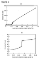
- Figs. 4(a) and 4(b) The change in the standardized band with respect to the amount of change in the phase match condition is shown in Figs. 4(a) and 4(b).
- Fig. 4(a) and Fig. 4(b) which is an enlarged view of Fig. 4(a)
- the bandwidth can be effectively increased. Therefore, in the present invention, means for changing the phase match condition by 0.235% or more from a state in which phases are matched is provided, so that the acoustooptic filter has a broad-band optical wavelength characteristic.
- the thin-film ridge 5 is formed along the longitudinal direction of the mutual action area, and has a film thickness which changes from 0.4 to 1.0 ⁇ m, thereby changing the phase speed of the surface wave at the mutual action area by 1%. Therefore, the phase match condition changes by nearly 1%, so that a broad-band light transmission characteristic is achieved.
- a broad-band light transmission characteristic can be achieved at low electrical power.
- the phase match condition is changed by increasing the thickness of the thin-film ridge 5 from the end 5a towards the end 5b.
- the width of a thin-film ridge 15 may be increased from an end 15a towards an end 15b.
- the thin-film ridge 15 has a length of 30 mm and a film thickness of 1.5 ⁇ m.
- the width at the end 15a is 20 ⁇ m, and the width at the end 15b is 40 ⁇ m.
- the other structural features of an acoustooptic filter 11 are the same as those of the acoustooptic filter 1.
- the width of the thin-film ridge 15 changes as mentioned above in a longitudinal direction of a mutual action area, so that the phase speed of a surface acoustic wave changes by nearly 1%.
- a broad-band light transmission characteristic can be achieved at low electrical power.
- the film thickness and the width of the thin-film ridge may both change along the longitudinal direction of the mutual action area by combining the first embodiment and the modification.
- Fig. 6 is a perspective view of an acoustooptic filter according to a second embodiment of the present invention.
- an acoustooptic filter 21 according to the second embodiment instead of the thin-film ridge 5 shown in Fig. 1, wall members 22 and 23 having respective wall surfaces 22a and 23a for reflecting a surface acoustic wave are disposed on a piezoelectric substrate 2.
- the other structural features of the acoustooptic filter 21 are the same as those of the acoustooptic filter 1.
- the wall surface 22a of the wall member 22 and the wall surface 23a of the wall member 23 extend parallel with each other and in a longitudinal direction of a mutual action area.
- the wall members 22 and 23 are formed of a material transmitting sound at a higher speed than LiNbO 3 forming the piezoelectric substrate 2. In the embodiment, they are formed of AIN. Diffusing Ti in LiNbO 3 produces a similar effect.
- the lengths of the wall surfaces 22a and 23a of the respective wall members 22 and 23 are 30 mm.
- the wall members 22 and 23 have film thicknesses that increase from respective ends 22b and 23b adjacent an IDT 4 towards respective opposite ends 22c and 23c.
- the heights of the wall surfaces 22a and 23a change so that they are 0.2 ⁇ m at the respective ends 22b and 23b and are 0.6 ⁇ m at the respective ends 22c and 23c.
- the pair of wall surfaces 22a and 23a for reflecting a surface wave are provided, thereby forming a surface wave waveguide for a surface acoustic wave excited at the IDT 4. Since the lengths of the pair of wall surfaces 22a and 23a change in the longitudinal direction of the mutual action area, the phase speed of the surface wave changes at the surface wave waveguide. Therefore, the aforementioned phase match condition changes by approximately 1%.
- the distance between wall surfaces 32a and 33a of respective wall members 32 and 33 may change in a longitudinal direction of a mutual action area as in an acoustooptic filter 31 in a modification shown in Fig. 7.
- the distance between the wall surface 32a and the wall surface 33a decreases from respective ends 32b and 33b adjacent to an IDT 4 towards respective opposite ends 32c and 33c.
- the distance between the wall surfaces 32a and 33a is 480 ⁇ m at the ends 32b and 33b and is 120 ⁇ m at the ends 33c and 32c.
- the phase match condition changes by approximately 1%. Therefore, it is similarly possible to achieve a broad light transmission band characteristic at low electrical power.
- the structure of the acoustooptic filter 21 according to the second embodiment and the structure of the acoustooptic filter 31 of the modification may be combined. More specifically, the heights of the pair of wall surfaces for propagating a surface wave at the surface acoustic wave waveguide and the distance between the pair of wall surfaces may both change in a longitudinal direction of the mutual action area.
- Fig. 8 is a perspective view of an acoustooptic filter according to a third embodiment.
- An acoustooptic filter 41 has the same structure as the acoustooptic filter 1 except that, instead of the thin-film ridge 5, a phase speed control film 42 is provided on a piezoelectric substrate 2.
- the phase speed control film 42 is formed by sputtering ZnO, and has a length of 30 nm in a longitudinal direction of a mutual action area and has a width equal to the overall width of the piezoelectric substrate 2.
- the phase speed control film 42 becomes thicker from an end 42a adjacent to an IDT 4 to an opposite end 42b. More specifically, the thickness at the end 42a is 0.4 ⁇ m, and the thickness at the end 42b is 1.0 ⁇ m.
- the phase speed control film 42 causes the phase speed of a surface acoustic wave to change as in the acoustooptic filter 1, so that the phase match condition changes by approximately 1%.
- phase match condition it is possible to change the aforementioned phase match condition by 0.235% or more from the state in which phases are matched by providing a temperature distribution to the mutual action area.
- means for providing a temperature distribution to the mutual action area may be used as the means for changing the phase match condition.
- a ZnO film is formed on a piezoelectric substrate 2 by sputtering ZnO.
- the thickness of the ZnO changes in a longitudinal direction of a mutual action area. Changing an input electrical power applied to an IDT 4 makes it possible to set a temperature gradient in the longitudinal direction of the mutual action area.
- FIG. 9 is a graph showing temperature distributions of the mutual action area when the thickness of the ZnO film is constant at 2 ⁇ m and the input electrical power is 50 mW, when the thickness of the ZnO film is constant at 2 ⁇ m and the input electrical power is 100 mW, and when the thickness of the ZnO film is constant at 5 ⁇ m and the input electrical power is 100 mW, respectively.
- a temperature gradient is set over the longitudinal direction of the mutual action area by selecting the thickness of the ZnO film and the input electrical power.
- the propagation coefficient of a surface acoustic wave or the effective refractive index of light are changed in the longitudinal direction of the mutual action area, so that the phase match condition is changed.
- the temperature gradient is set so that the phase match condition changes by 0.235% or more from the state in which phases are matched. Therefore, it can be understood that, like the acoustooptic filter 1 according to the first embodiment, the acoustooptic filter according to the fourth embodiment provides a broad light transmission characteristic without reducing the length of the mutual action area.
- the ZnO film is provided, it does not need to be provided, in which case only a heating element of the IDT 4 may be changed by controlling the input electrical power.
- a temperature gradient may be set by changing the thickness of the ZnO film in the longitudinal direction of the mutual action area like the thin-film ridge 5.
- heaters 52 and 53 may be disposed on an upper surface 2a of a piezoelectric substrate 2. By disposing the heaters 52 and 53 near a mutual action area, it is possible to set a temperature gradient in a longitudinal direction of the mutual action area.
- Fig. 11 is a perspective view of an acoustooptic filter according to a fifth embodiment of the present invention.
- an optical waveguide 63 is provided in an upper surface 2a of a piezoelectric substrate 2.
- the width of the optical waveguide 63 changes in a longitudinal direction of a mutual action area. More specifically, the optical waveguide 63, which is formed by thermally diffusing Ti, has a width of 6 ⁇ m at a side where an IDT 4 is disposed and a width of 8 ⁇ m at an outer end of the mutual action area, that is, at an end 63a of the optical waveguide 63.
- a ZnO film 64 is provided at the mutual action area to change the phase speed of a surface wave, the ZnO film 64 does not necessarily have to be provided.
- the width of the optical waveguide 63 changes as mentioned above in the longitudinal direction of the mutual action area, so that the phase match condition changes from the state in which phases are matched. Therefore, by changing the width of the optical waveguide 63 so that the phase match condition changes by 0.235% or more from the state in which the phases are matched, the acoustooptic filter 61 can provide a broad light transmission characteristic without reducing the length of the mutual action area like the acoustooptic filter 1 according to the first embodiment.
- the width of the optical waveguide 63 changes in the longitudinal direction of the mutual action area
- the depth of the optical waveguide 63 may change.
- the depth of the area in which Ti is diffused that is, the thickness of the optical waveguide 63 changes in the range of from 80 to 100 nm, it is possible to, as with the acoustooptic filter 61, change the phase match condition by 0.235% or more.
- the acoustooptic substrate used in the present invention may be a cut angle LiNbO 3 substrate or other types of piezoelectric substrates instead of an X-cut Y-propagating LiNbO 3 substrate.
- the acoustooptic filter according to the present invention comprises phase match condition changing means for changing a phase match condition at the mutual action area by 0.235% or more from the state in which phases are matched, the mutual action area being an area where light guided to the optical waveguide and a surface acoustic wave act upon each other. Therefore, it is possible to provide a broad light transmission characteristic without reducing the length of the mutual action area. Consequently, it is possible to provide a broad transmission characteristic at low electrical power.
- phase match condition changing means is means for changing the phase speed of the surface acoustic wave at the mutual action area
- a structure for changing the phase speed of the surface acoustic wave only needs to be provided at the mutual action area to make it possible to provide a broad-band light transmission characteristic in accordance with the present invention.
- the means for changing the phase speed of a surface acoustic wave or a thin-film ridge is provided at the surface wave waveguide, it is possible to easily change the phase speed of the surface wave.
- the thickness of the thin-film ridge along the surface wave waveguide it is possible to easily change the phase speed of the surface acoustic wave at the surface wave waveguide.
- phase speed at the surface wave waveguide by making use of a pair of wall surfaces for reflecting the surface wave, the pair of wall surfaces being disposed, one at each side of the surface wave waveguide.
- the structures of the wall members having the respective wall surfaces may change along the surface wave waveguide.
- the phase match condition changing means may be a phase speed control film for changing the phase speed of the surface acoustic wave at the mutual action area.
- the thickness of the phase speed control film is set so that the phase match condition changes by 0.235% or more.
- the phase match condition changing means may be means for changing the propagation coefficient or an effective refractive index of light at the mutual action area.
- An example of such means is temperature distribution setting means for setting a temperature gradient at the mutual action area. Therefore, for example, a heating element or a heater may be provided on the acoustooptic substrate, or an interdigital electrode may be used as a heating element by controlling the input electrical power of the interdigital electrode itself.
- the temperature distribution setting means may be formed by using a thin film that is provided on the surface wave waveguide, in which case the thickness of the thin film may partly differ so as to possess the temperature distribution. This makes it possible to easily set the temperature distribution at the mutual action area, so that it is possible to achieve a broad light transmission characteristic at low electrical power by changing the phase match condition in accordance with the present invention.
- the means for changing the propagation coefficient of the surface wave or the effective refractive index of light at the mutual action area may be provided by the optical waveguide itself.
- the width of the optical waveguide may change in the longitudinal direction of the mutual action area so that the phase match condition changes by 0.235% or more, or the depth of the metal diffusion area in which metal is diffused for forming the optical waveguide, that is, the depth of the optical waveguide may change in the longitudinal direction of the mutual action area, so that the phase match condition changing means is formed. Therefore, it is possible to easily provide an acoustooptic filter having a broad light transmission characteristic at low electrical power by only controlling the method of diffusing the metal.
Landscapes
- Physics & Mathematics (AREA)
- Nonlinear Science (AREA)
- General Physics & Mathematics (AREA)
- Optics & Photonics (AREA)
- Optical Modulation, Optical Deflection, Nonlinear Optics, Optical Demodulation, Optical Logic Elements (AREA)
- Optical Integrated Circuits (AREA)
Applications Claiming Priority (2)
| Application Number | Priority Date | Filing Date | Title |
|---|---|---|---|
| JP2003193133 | 2003-07-07 | ||
| PCT/JP2004/005780 WO2005003847A1 (fr) | 2003-07-07 | 2004-04-22 | Filtre acoustico-optique |
Publications (2)
| Publication Number | Publication Date |
|---|---|
| EP1643295A1 true EP1643295A1 (fr) | 2006-04-05 |
| EP1643295A4 EP1643295A4 (fr) | 2010-02-17 |
Family
ID=33562443
Family Applications (1)
| Application Number | Title | Priority Date | Filing Date |
|---|---|---|---|
| EP04728935A Withdrawn EP1643295A4 (fr) | 2003-07-07 | 2004-04-22 | Filtre acoustico-optique |
Country Status (6)
| Country | Link |
|---|---|
| US (1) | US7343056B2 (fr) |
| EP (1) | EP1643295A4 (fr) |
| JP (1) | JP4111221B2 (fr) |
| KR (1) | KR100742514B1 (fr) |
| CN (1) | CN100360990C (fr) |
| WO (1) | WO2005003847A1 (fr) |
Families Citing this family (5)
| Publication number | Priority date | Publication date | Assignee | Title |
|---|---|---|---|---|
| WO2008041448A1 (fr) * | 2006-10-04 | 2008-04-10 | Murata Manufacturing Co., Ltd. | Filtre acousto-optique |
| US10312596B2 (en) * | 2013-01-17 | 2019-06-04 | Hrl Laboratories, Llc | Dual-polarization, circularly-polarized, surface-wave-waveguide, artificial-impedance-surface antenna |
| US10983194B1 (en) | 2014-06-12 | 2021-04-20 | Hrl Laboratories, Llc | Metasurfaces for improving co-site isolation for electronic warfare applications |
| CN105388640B (zh) * | 2015-12-29 | 2019-08-02 | 中国电子科技集团公司第二十六研究所 | 用于声光可调滤光器的倾斜式换能器装置 |
| CN108344800B (zh) * | 2018-01-17 | 2020-04-14 | 浙江大学 | 基于无线无源声表面波传感器的温度检测系统及收发系统 |
Family Cites Families (18)
| Publication number | Priority date | Publication date | Assignee | Title |
|---|---|---|---|---|
| JPS6412710A (en) * | 1987-07-07 | 1989-01-17 | Furukawa Electric Co Ltd | Surface acoustic wave element |
| JPS6412710U (fr) * | 1987-07-10 | 1989-01-23 | ||
| JPH01184331A (ja) * | 1988-01-19 | 1989-07-24 | Aoki Hiroaki | 足熱ストーブ |
| JPH0667235A (ja) | 1992-08-24 | 1994-03-11 | Sanyo Electric Co Ltd | 波長変換装置 |
| US5400171A (en) * | 1993-10-01 | 1995-03-21 | Bell Communications Research, Inc. | Acousto-optic filter with near-ideal bandpass characteristics |
| EP0698224A1 (fr) * | 1994-03-11 | 1996-02-28 | Koninklijke Philips Electronics N.V. | Dispositif servant a augmenter la frequence d'un rayonnement electromagnetique |
| US5452314A (en) * | 1994-08-01 | 1995-09-19 | Hewlett-Packard Company | Controllable-birefringence, acousto-optic tunable filter and a laser tuned by the same |
| JPH0850267A (ja) | 1994-08-08 | 1996-02-20 | Nec Corp | 音響光学フィルタ |
| KR100265865B1 (ko) * | 1997-06-16 | 2000-09-15 | 윤덕용 | 광섬유가변형파장필터 |
| JP3836950B2 (ja) * | 1997-07-02 | 2006-10-25 | 富士通株式会社 | 音響光学デバイス |
| WO1999006876A1 (fr) * | 1997-07-31 | 1999-02-11 | Pirelli Cavi E Sistemi S.P.A. | Dispositifs acousto-optiques presentant une structure d'attenuateur acoustique |
| JP3861395B2 (ja) | 1997-08-11 | 2006-12-20 | 富士通株式会社 | 光導波路デバイス及び光導波路デバイスを用いた光通信システム |
| JP3978263B2 (ja) * | 1997-09-05 | 2007-09-19 | 富士通株式会社 | 光フィルタ装置 |
| US6535665B1 (en) * | 1998-02-12 | 2003-03-18 | Novera Optics, Inc. | Acousto-optic devices utilizing longitudinal acoustic waves |
| JP3165106B2 (ja) | 1998-05-19 | 2001-05-14 | 日本電気株式会社 | 光可変波長フィルタ |
| JP2001228450A (ja) * | 2000-02-18 | 2001-08-24 | Fujitsu Ltd | 音響光学チューナブルフィルタ |
| US6556729B2 (en) * | 2001-07-27 | 2003-04-29 | The United States Of America As Represented By The National Security Agency | Acousto-optic bandpass filter |
| US6647159B1 (en) * | 2002-01-25 | 2003-11-11 | The United States Of America As Represented By The National Security Agency | Tension-tuned acousto-optic bandpass filter |
-
2004
- 2004-04-22 US US10/561,772 patent/US7343056B2/en not_active Expired - Fee Related
- 2004-04-22 EP EP04728935A patent/EP1643295A4/fr not_active Withdrawn
- 2004-04-22 JP JP2005511307A patent/JP4111221B2/ja not_active Expired - Fee Related
- 2004-04-22 CN CNB2004800180865A patent/CN100360990C/zh not_active Expired - Fee Related
- 2004-04-22 KR KR1020057024494A patent/KR100742514B1/ko not_active Expired - Fee Related
- 2004-04-22 WO PCT/JP2004/005780 patent/WO2005003847A1/fr not_active Ceased
Also Published As
| Publication number | Publication date |
|---|---|
| KR20060030049A (ko) | 2006-04-07 |
| CN1813215A (zh) | 2006-08-02 |
| WO2005003847A1 (fr) | 2005-01-13 |
| CN100360990C (zh) | 2008-01-09 |
| KR100742514B1 (ko) | 2007-07-24 |
| JPWO2005003847A1 (ja) | 2006-08-17 |
| US20070147723A1 (en) | 2007-06-28 |
| US7343056B2 (en) | 2008-03-11 |
| EP1643295A4 (fr) | 2010-02-17 |
| JP4111221B2 (ja) | 2008-07-02 |
Similar Documents
| Publication | Publication Date | Title |
|---|---|---|
| EP0938000B1 (fr) | Branchement de guides d'ondes optiques avec réflecteur | |
| US6259847B1 (en) | Optical communication system including broadband all-pass filter for dispersion compensation | |
| US20020176659A1 (en) | Dynamically tunable resonator for use in a chromatic dispersion compensator | |
| EP2015112B1 (fr) | Dispositif a guide d'ondes optiques | |
| EP0724173A1 (fr) | Filtres monolithiques à guides d'ondes optiques conçus selon un développement en série de Fourier | |
| US7245792B2 (en) | Silicon-based tunable single passband optical filter | |
| US20020008913A1 (en) | Single resonant band, tunable optical fiber wavelength filter based on long-period fiber grating | |
| CN117215132B (zh) | 一种可用于多波长通道发射器的fp腔电光调制器阵列 | |
| EP0721597A1 (fr) | Filtre acousto-optique a caracteristiques passe-bande quasi ideales | |
| JP3311722B2 (ja) | リング共振器付き光導波路型波長フィルタおよび1×n光導波路型波長フィルタ | |
| CN101196596A (zh) | 基于双环谐振腔的可调光学陷波滤波器 | |
| US5446807A (en) | Passband-flattened acousto-optic polarization converter | |
| US20020197011A1 (en) | Method and apparatus for tuning a bragg grating in a semiconductor substrate | |
| US20020197012A1 (en) | Method and apparatus for adding/droping optical signals in a semiconductor substrate | |
| EP1643295A1 (fr) | Filtre acoustico-optique | |
| JPH08211349A (ja) | 波長可変光フィルタ | |
| EP1591810A1 (fr) | Technique d'apodisation de réseau pour des guides d'onde fabriqués par diffusion | |
| EP0720042A1 (fr) | Filtre optique utilisant un matériau électro-optique | |
| EP0480370A1 (fr) | Filtre de longueur d'onde du type guide d'ondes | |
| US6233372B1 (en) | Waveguide path type polarization independent optical wavelength tunable filter | |
| US7430344B2 (en) | Acousto-optic device and fabrication method of acousto-optic device | |
| US7167293B2 (en) | Silicon-based electro-optic phase modulator with reduced residual amplitude modulation | |
| EP0887688A2 (fr) | Filtres optiques é longueur d'onde accordable | |
| US6441962B1 (en) | Optical filter with little variation in chromatic dispersion | |
| JPH05323248A (ja) | 可同調光フィルタ |
Legal Events
| Date | Code | Title | Description |
|---|---|---|---|
| PUAI | Public reference made under article 153(3) epc to a published international application that has entered the european phase |
Free format text: ORIGINAL CODE: 0009012 |
|
| 17P | Request for examination filed |
Effective date: 20051201 |
|
| AK | Designated contracting states |
Kind code of ref document: A1 Designated state(s): AT BE BG CH CY CZ DE DK EE ES FI FR GB GR HU IE IT LI LU MC NL PL PT RO SE SI SK TR |
|
| DAX | Request for extension of the european patent (deleted) | ||
| RAP1 | Party data changed (applicant data changed or rights of an application transferred) |
Owner name: MURATA MANUFACTURING CO., LTD. |
|
| A4 | Supplementary search report drawn up and despatched |
Effective date: 20100118 |
|
| RIC1 | Information provided on ipc code assigned before grant |
Ipc: G02F 1/125 20060101AFI20050114BHEP |
|
| 17Q | First examination report despatched |
Effective date: 20100825 |
|
| STAA | Information on the status of an ep patent application or granted ep patent |
Free format text: STATUS: THE APPLICATION IS DEEMED TO BE WITHDRAWN |
|
| 18D | Application deemed to be withdrawn |
Effective date: 20140207 |