EP1643348A2 - Procédé de blocage d'un signal de réveil - Google Patents
Procédé de blocage d'un signal de réveil Download PDFInfo
- Publication number
- EP1643348A2 EP1643348A2 EP05107471A EP05107471A EP1643348A2 EP 1643348 A2 EP1643348 A2 EP 1643348A2 EP 05107471 A EP05107471 A EP 05107471A EP 05107471 A EP05107471 A EP 05107471A EP 1643348 A2 EP1643348 A2 EP 1643348A2
- Authority
- EP
- European Patent Office
- Prior art keywords
- signal
- wake
- temperature
- control unit
- transistor
- Prior art date
- Legal status (The legal status is an assumption and is not a legal conclusion. Google has not performed a legal analysis and makes no representation as to the accuracy of the status listed.)
- Granted
Links
Images
Classifications
-
- G—PHYSICS
- G06—COMPUTING OR CALCULATING; COUNTING
- G06F—ELECTRIC DIGITAL DATA PROCESSING
- G06F1/00—Details not covered by groups G06F3/00 - G06F13/00 and G06F21/00
- G06F1/24—Resetting means
-
- G—PHYSICS
- G06—COMPUTING OR CALCULATING; COUNTING
- G06F—ELECTRIC DIGITAL DATA PROCESSING
- G06F1/00—Details not covered by groups G06F3/00 - G06F13/00 and G06F21/00
- G06F1/26—Power supply means, e.g. regulation thereof
Definitions
- the invention relates to a method for locking a wake-up signal, an over-temperature circuit, a computer program and a computer program product.
- An operation of a controller may be affected by its temperature or the temperature of the environment in which the controller is located. A temperature-related damage to the control unit can be avoided if switching on the control unit is avoided outside a designated temperature range.
- the method according to the invention serves to lock a control unit to be awakened by a wake-up signal, wherein the wake-up signal is blocked by an over-temperature circuit.
- the control unit can only be awakened by the wake-up signal and start an operation in which it possibly carries out control functions for controlling one or more other devices.
- the wake-up signal is blocked once. If the wake-up signal is blocked by the overtemperature shutdown and thus the hardware, a waking up of the control unit is suppressed, so that a waking up of the control unit is not possible.
- the overtemperature shutdown which may be implemented as hardware-side interlocking electronics, may be controlled by suitable software or a suitable program, wherein blocking of the wake-up signal is triggered by this software or this program.
- the wake-up signal When executing the method, it may be provided that the wake-up signal is blocked above a critical temperature or a shutdown temperature. This prevents the control unit from waking up above this temperature.
- the wake-up signal may be below a critical temperature, within one Temperature range or outside a temperature range.
- the method is performed taking into account a temperature of the controller. If the temperature of the controller is above the critical temperature or reaches a value above this critical temperature, the wake-up signal for the controller is blocked by the over-temperature circuit.
- the method is carried out taking into account or depending on a temperature of at least one other device.
- This device may be in indirect or direct interaction with the controller and may be controlled by the controller, for example. If the temperature of this device is above the critical temperature or should reach this critical temperature, the wake-up signal is permanently blocked by the over-temperature circuit.
- the control unit is usually housed in a technical device, such as a vehicle.
- the method may be performed at a start of the controller initiated by a starting device, typically by an ignition key.
- the awakening of the control unit so that this receives control functions, can only be initiated when the wake-up signal can reach the controller and therefore is not blocked.
- the controller can not be woken up at the start.
- the control unit can always be woken up with the help of the ignition key over a first path.
- the locking by the over-temperature circuit relates here to a second path, for example a CAN (controller area network), which is provided for waking up the control unit. In the invention, it is intended to permanently block only one of these two paths.
- the method by the overtemperature a permanent blocking of the wake-up signal is triggered once.
- the one-time triggered by the overtemperature circuit interlock is not canceled by lowering the temperature, either the temperature of the controller and / or the device below the critical temperature.
- the wake-up signal is permanently blocked by the over-temperature circuit.
- the overtemperature circuit thus permanently locks the wake of the control unit by the wake-up signal provided via the signal path, for example a controller area network (CAN), as soon as the over-temperature circuit has triggered the blocking once when the critical temperature has been reached.
- CAN controller area network
- the blocking or the so-called permanent blocking of the wake-up signal can be reset at a start of the control device initiated by the starting device. This is the case, for example, when the temperature is below the critical temperature.
- the wake-up signal may then reach the controller at the start again.
- the wake-up signal is blocked by a transistor in the overtemperature circuit.
- the transistor is integrated into the signal path in such a way that the wake-up signal provided for the control unit is passed through the transistor is derived from the signal path. This takes place as a function of the temperature, wherein the transistor can be influenced by a temperature-sensitive component, for example.
- the transistor can be switched by a bistable element of the overtemperature circuit. A signal path between the control unit and another electronic device via which the wake-up signal is to be transmitted is blocked in this case by the transistor, so that the wake-up signal sent by the further device does not reach the control unit.
- the overtemperature circuit can also be arranged within a control unit or the control unit.
- the bistable element for switching the transistor changes its states as a function of the temperature of the control device and / or the device and, influenced by the temperature-sensitive device, can change its state.
- the over-temperature circuit according to the invention for a control unit is designed to lock a wake-up signal, with which the control unit is to be awakened.
- the overtemperature circuit may be designed as a locking electronics and is actuated upon reaching the critical temperature by means of software, so that with the overtemperature circuit triggered by the software hardware-locking of the controller is realized.
- the overtemperature circuit can be accommodated, for example, in the control unit.
- the overtemperature circuit or at least one temperature-sensitive component of the Overtemperature circuit may have a temperature profile that corresponds to at least a maximum temperature profile of the controller.
- the over-temperature circuit or the temperature-sensitive device may have characteristics of a temperature sensor.
- a temperature characteristic or the temperature profile of the overtemperature circuit or the module is adapted to a temperature characteristic or the temperature profile of the controller or the device that the overtemperature circuit can reliably respond to temperature changes of the controller and blocks the wake-up signal for the controller when the temperature above the critical temperature is located.
- the over-temperature circuit may comprise a bistable element, such as a flip-flop, and a transistor, the bistable element depending on a value of a temperature, possibly influenced by the temperature-sensitive device, its states and thus switches the transistor.
- the temperature-sensitive module can also be designed such that it switches the transistor directly, so that it is possible to dispense with the bistable element.
- the computer program with program code means according to the invention is intended to carry out all steps of the method according to the invention when the computer program is executed on a computer or a corresponding arithmetic unit.
- the computer program product according to the invention comprises program code means which are stored on a computer-readable data carrier in order to carry out the method according to the invention when the computer program is open a computer or a corresponding arithmetic unit is performed.
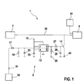
- the overtemperature circuit 3 has a transistor 11, for example. a T100, designed as a JK flip-flop bistable element 13, a connection to a voltage source 15 and various resistors and capacitors.
- This may be an electrical resistor 17, for example a R110 having a resistance of 100 k ⁇ , an electrical resistor 19, for example a R111 having a resistance of 1 M ⁇ , a capacitor 21, for example a C110 having a capacitance of 10 nF, a capacitor 23, for example, a C101 having a capacitance of 10 nF, an electric resistance 25, for example, a R101 having a resistance of 100 k ⁇ , an electric resistance 27, for example, a R100 having a resistance of 100 k ⁇ , and a capacitor 29, for example a C100 with a capacitance of 10 nF act.
- the overtemperature circuit 3 has a first output 31, via which the overtemperature circuit 3 is connected to a temperature-sensitive component 33. Furthermore, the overtemperature circuit 3 has an analog-digital output 35.
- the control unit 5 and the electrical device 7, which are arranged within the control unit 1, are connected to one another via a signal path 39. Furthermore, this control unit 5 is connected to a starting device 41, for example an ignition key.
- the transistor 11 is integrated in the signal path 39 between the control unit 5 and the electrical device 7 such that the transistor 11 derives a signal to be transported via the signal path 39 as a function of how it is connected to a ground 43 and the signal thus blocked or releases the signal path 39 and thus the signal reaches the control unit 5.
- the starter 41 is configured to reset or start the controller 5.
- a wake-up signal generated by the electrical device 7 can be transmitted via the signal path 39 to the control unit 5 when the transistor 11 is disabled. With the wake-up signal, it is possible to wake the control unit 5.
- the overtemperature circuit 3 is designed to block the wake-up signal as a function of temperature and thus to lock the control unit 5. It is provided that the wake-up signal is blocked in consideration of a temperature of the control unit 5.
- the temperature of the control unit 5 is detected by the temperature-sensitive module 33, which has a temperature profile which corresponds to at least one maximum temperature profile of the control unit 5. This means that the module 33 can reliably distinguish whether the temperature of the control unit 5 is above or below the critical temperature or equal to this critical temperature.
- the temperature profile of the module 33 and thus also a temperature profile of the overtemperature circuit 3, for example, in the region of the critical temperature of the control unit 5 may be particularly sensitive.
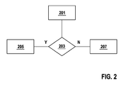
- the temperature-sensitive component 33 influences the two possible positions of the bistable element 13 as a function of the temperature of the control unit 5. Possible possibilities for a function of the control unit 5 are thereby obtained illustrated by the method steps 201, 203, 205, 207 of the flowchart shown in Figure 2.
- a software-controlled check 203 takes place.
- the transistor 11 is switched by the bistable element 13 such that the transistor 11 releases a path of the wake-up signal along the signal path 39 and the wake-up signal reaches the control unit 5, so that the control unit 5 can be awakened.
- the transistor 11 is switched by the bistable element 13 such that the wake-up signal is blocked. Since the wake-up signal does not reach the control unit 5 in this case, the control unit 5 is locked and can not be woken up via the signal path 39.
- the control unit 5 Upon a first actuation of the starter 41, the control unit 5 is awakened. The status of the transistor 11 can be queried via the analog-digital input 35. If the temperature of the controller 5 should be less than the critical temperature after previously above this critical temperature or was equal to this critical temperature, the software can toggle on the input 31 and for the bistable element 13 a set desired state.
- the software can toggle via the input 31 and set the bistable element 13 such that the transistor 11 derives the wake-up signal and the controller 5 locks is or remains locked.
- the transistor 11 is set by the bistable element 13 in the corresponding state and remains supplied via the voltage source 15 with the voltage U_STBY. A wake-up of the control device 5 starting from the electronic device 7 is therefore not possible.
- control unit 5 If a wake-up of the control unit 5 is provided, then it must be reset via the starting device 41 and thus awakened, but then there is always a check via the software. Due to the design and operation of the overtemperature circuit 3, it is therefore not possible to wake the control unit 5, if the temperature of the control unit 5 is greater than or equal to the critical temperature.
- the entire arrangement 1 can be arranged in a vehicle.
- the locking of the control unit 5 by blocking the wake-up signal can also take place as a function of another device, for example a transmission of the vehicle, and thus independent of the temperature of the control device 5.
- a critical temperature for the functioning of the transmission maximum allowable temperature of, for example. 150 ° C can be selected. Above this temperature in the transmission, therefore, the awakening of the control unit is prevented.
- the starter 41 may be an ignition key of the vehicle to be operated by an ignition key (terminal 15). The reset of the control unit 5 is possible with a corresponding signal of the ignition.
- the control unit 5 for a transmission can be woken up within a CAN network or within the control unit 1 via one or more signal paths 39.
- control device 5 after an initiated awakening outside critical operating parameters, in this case above the critical temperature, is not possible.
- the locking of the control unit 5 by blocking the wake-up signal by the overtemperature circuit 3 takes place on the hardware side.
- the overtemperature circuit 3 can also be accommodated inside the control unit 5, which can be designed as a stabilizing ASIC, so that an optimal ratio of silicon area to ceramic area can be achieved within the control unit 5 with such a configuration. It is also conceivable to use the overtemperature circuit 3 in a so-called LIN wake-up.
Landscapes
- Engineering & Computer Science (AREA)
- Theoretical Computer Science (AREA)
- Physics & Mathematics (AREA)
- General Engineering & Computer Science (AREA)
- General Physics & Mathematics (AREA)
- Lock And Its Accessories (AREA)
- Semiconductor Integrated Circuits (AREA)
- Control Of Electric Motors In General (AREA)
- Control Of Temperature (AREA)
Priority Applications (1)
| Application Number | Priority Date | Filing Date | Title |
|---|---|---|---|
| PL05107471T PL1643348T3 (pl) | 2004-09-29 | 2005-08-15 | Sposób blokowania sygnału budzenia |
Applications Claiming Priority (1)
| Application Number | Priority Date | Filing Date | Title |
|---|---|---|---|
| DE102004047181A DE102004047181A1 (de) | 2004-09-29 | 2004-09-29 | Verfahren zur Verriegelung eines Aufwecksignals |
Publications (3)
| Publication Number | Publication Date |
|---|---|
| EP1643348A2 true EP1643348A2 (fr) | 2006-04-05 |
| EP1643348A3 EP1643348A3 (fr) | 2012-03-14 |
| EP1643348B1 EP1643348B1 (fr) | 2019-12-04 |
Family
ID=35149016
Family Applications (1)
| Application Number | Title | Priority Date | Filing Date |
|---|---|---|---|
| EP05107471.4A Expired - Lifetime EP1643348B1 (fr) | 2004-09-29 | 2005-08-15 | Procédé de blocage d'un signal de réveil |
Country Status (7)
| Country | Link |
|---|---|
| US (1) | US9465419B2 (fr) |
| EP (1) | EP1643348B1 (fr) |
| JP (1) | JP4974207B2 (fr) |
| DE (1) | DE102004047181A1 (fr) |
| ES (1) | ES2769373T3 (fr) |
| HU (1) | HUE048631T2 (fr) |
| PL (1) | PL1643348T3 (fr) |
Families Citing this family (4)
| Publication number | Priority date | Publication date | Assignee | Title |
|---|---|---|---|---|
| US20090067616A1 (en) * | 2007-09-07 | 2009-03-12 | Kerby William Suhre | CAN echo cancellation level shifter |
| DE102011084963A1 (de) * | 2011-10-21 | 2013-04-25 | Robert Bosch Gmbh | Vorrichtung und Verfahren zum sicheren Erkennen von Weckereignissen in der Phase des Abschaltens eines Steuergerätes |
| US9274805B2 (en) * | 2012-02-24 | 2016-03-01 | Qualcomm Incorporated | System and method for thermally aware device booting |
| FR3126549A1 (fr) * | 2021-08-27 | 2023-03-03 | Psa Automobiles Sa | Procede de protection d’un circuit imprime d’un calculateur de gestion d’une batterie haute tension |
Family Cites Families (21)
| Publication number | Priority date | Publication date | Assignee | Title |
|---|---|---|---|---|
| GB1036104A (en) * | 1961-07-26 | 1966-07-13 | Findlay Irvine Ltd | A temperature-indicating device |
| US3575617A (en) * | 1968-12-27 | 1971-04-20 | Rca Corp | Field effect transistor, content addressed memory cell |
| US4264035A (en) * | 1978-09-22 | 1981-04-28 | Barber-Colman Company | Dual reset controller |
| US4419730A (en) * | 1980-02-18 | 1983-12-06 | Nippondenso Co., Ltd. | Method and system for controlling the setting temperature of a vehicle air conditioner |
| US4499733A (en) * | 1980-06-16 | 1985-02-19 | Farr Company | Emergency shutdown mechanism for a turbocharged diesel engine |
| US4532606A (en) * | 1983-07-14 | 1985-07-30 | Burroughs Corporation | Content addressable memory cell with shift capability |
| DE3718471A1 (de) * | 1987-06-02 | 1988-12-22 | Christoph Breit | Einrichtung zum schutz der aggregate und der ladung von kraftfahrzeugen |
| DE3922506A1 (de) * | 1989-07-08 | 1991-01-17 | Bosch Gmbh Robert | Insassen-sicherheitssystem fuer fahrzeuge |
| JPH03244868A (ja) * | 1990-02-20 | 1991-10-31 | Mitsubishi Electric Corp | 自動変速機の油温センサ故障判定装置 |
| JPH0498508A (ja) * | 1990-08-17 | 1992-03-31 | Nec Corp | 電源制御方式 |
| DE4236334A1 (de) * | 1992-10-28 | 1994-05-05 | Bosch Gmbh Robert | Monolithisch integriertes MOS-Endstufenbauteil mit einer Überlast-Schutzeinrichtung |
| JP2000039937A (ja) * | 1998-07-22 | 2000-02-08 | Toshiba Corp | コンピュータシステムおよびそのパワーセーブ制御方法 |
| US6119950A (en) * | 1998-08-21 | 2000-09-19 | Albanello; Frank A. | Thermostat with load relay cycling feature |
| US6131539A (en) * | 1999-06-30 | 2000-10-17 | Detroit Diesel Corporation | System and method for enhanced engine monitoring and protection |
| US6415761B1 (en) * | 2000-05-11 | 2002-07-09 | Detroit Diesel Corporation | Engine over temperature protection |
| US6604909B2 (en) * | 2001-03-27 | 2003-08-12 | Aquatec Water Systems, Inc. | Diaphragm pump motor driven by a pulse width modulator circuit and activated by a pressure switch |
| JP3941441B2 (ja) * | 2001-09-11 | 2007-07-04 | トヨタ自動車株式会社 | 内燃機関の始動時制御装置 |
| JP3760840B2 (ja) * | 2001-11-09 | 2006-03-29 | 日産自動車株式会社 | 車両のエンジン自動停止・自動再始動装置 |
| DE10157802B4 (de) * | 2001-11-27 | 2016-02-04 | E.E.P.D. Electronic Equipment Produktion & Distribution Gmbh | Fahrzeug, sowie Verfahren zur Steuerung des Betriebs von an einem Kommunikationsbus eines Fahrzeugs angeschlossenen elektrischen oder elektronischen Komponenten |
| JP4349605B2 (ja) * | 2002-01-18 | 2009-10-21 | 株式会社デンソー | 自動車用制御装置 |
| US7072761B2 (en) * | 2002-10-10 | 2006-07-04 | Detroit Diesel Corporation | Redundant engine shutdown system |
-
2004
- 2004-09-29 DE DE102004047181A patent/DE102004047181A1/de not_active Withdrawn
-
2005
- 2005-08-15 ES ES05107471T patent/ES2769373T3/es not_active Expired - Lifetime
- 2005-08-15 HU HUE05107471A patent/HUE048631T2/hu unknown
- 2005-08-15 EP EP05107471.4A patent/EP1643348B1/fr not_active Expired - Lifetime
- 2005-08-15 PL PL05107471T patent/PL1643348T3/pl unknown
- 2005-09-29 JP JP2005283314A patent/JP4974207B2/ja not_active Expired - Lifetime
- 2005-09-29 US US11/241,273 patent/US9465419B2/en not_active Expired - Fee Related
Also Published As
| Publication number | Publication date |
|---|---|
| PL1643348T3 (pl) | 2020-06-01 |
| JP2006096342A (ja) | 2006-04-13 |
| US9465419B2 (en) | 2016-10-11 |
| JP4974207B2 (ja) | 2012-07-11 |
| EP1643348B1 (fr) | 2019-12-04 |
| DE102004047181A1 (de) | 2006-03-30 |
| HUE048631T2 (hu) | 2020-08-28 |
| EP1643348A3 (fr) | 2012-03-14 |
| ES2769373T3 (es) | 2020-06-25 |
| US20060065751A1 (en) | 2006-03-30 |
Similar Documents
| Publication | Publication Date | Title |
|---|---|---|
| DE69633653T2 (de) | Zündsystem für Brennkraftmaschine | |
| DE102011081908B4 (de) | Elektronische Steuereinrichtung | |
| EP1967831B1 (fr) | Outil de détachement à température | |
| EP2829929B1 (fr) | Appareil de terrain avec un affichage et/ou une unité d'entrée détachable | |
| EP2550740B1 (fr) | Élément électronique pour un dispositif de capteur, dispositif de capteur et procédé de configuration d'un dispositif de capteur | |
| DE102016206588A1 (de) | Synchron-Tiefsetzsteller mit Schutz vor Kurzschluss zu einer Spannungsquelle | |
| EP2616827B1 (fr) | Dispositif de surveillance de paramètres de fonctionnement de circuits intégrés et circuit intégré doté d'une surveillance de paramètres | |
| DE102004026383B4 (de) | Kraftfahrzeug mit mindestens einem von einem Prozessor gesteuerten Steuergerät | |
| EP1643348B1 (fr) | Procédé de blocage d'un signal de réveil | |
| EP2506436A2 (fr) | Circuit d'entrée pour un composant d'entrée et procédé de fonctionnement d'un circuit d'entrée | |
| EP0863450A1 (fr) | Circuit pour la régulation de courant d'un appareil de chauffage de siège en fonction de la température | |
| EP1371138B1 (fr) | Dispositif de mise en forme d'un signal d'entree pour ligne mal adaptee en sortie | |
| DE102010005671B3 (de) | Verfahren zum Steuern einer Heizeinrichtung und Heizeinrichtung | |
| DE102007019102B4 (de) | Steuervorrichtung und Steuerverfahren für ein elektrisches Haushaltsgerät | |
| EP1748299B1 (fr) | Circuit électronique, système avec un circuit électronique et procédé pour tester un circuit électronique | |
| EP0483450B1 (fr) | Dispositif de circuit en tant qu'élément avec au moins un actionneur semi-conducteur pour mettre en circuit | |
| EP3399632A1 (fr) | Commande de commutateurs de puissance à semi-conducteur | |
| DE102024125178A1 (de) | Sicherheitsschaltung mit einem steuerbaren elektronischen Regel- und/oder Schaltelement und eine Elektronikkomponente sowie ein Verfahren | |
| DE102013020583A1 (de) | Sensorelement mit einem Überspannungsschutz | |
| DE102014200052A1 (de) | Schaltungsanordnung mit einem Steuergerät mit integrierter oder nachgeschalteter Trenneinrichtung | |
| DE102019108304B3 (de) | Elektronische Schaltungsanordnung zur Temperaturüberwachung | |
| DE102008008666B4 (de) | Schaltungsanordnung | |
| DE102017223487B4 (de) | Verfahren zum Betreiben einer Schaltungsanordnung sowie entsprechende Schaltungsanordnung | |
| EP0564836A1 (fr) | Circuit de surveillance avec au moins un module de calcul | |
| WO2024245670A1 (fr) | Procédé de fonctionnement d'un dispositif de terrain ayant une unité de collecte d'énergie et dispositif de terrain |
Legal Events
| Date | Code | Title | Description |
|---|---|---|---|
| PUAI | Public reference made under article 153(3) epc to a published international application that has entered the european phase |
Free format text: ORIGINAL CODE: 0009012 |
|
| AK | Designated contracting states |
Kind code of ref document: A2 Designated state(s): AT BE BG CH CY CZ DE DK EE ES FI FR GB GR HU IE IS IT LI LT LU LV MC NL PL PT RO SE SI SK TR |
|
| AX | Request for extension of the european patent |
Extension state: AL BA HR MK YU |
|
| PUAL | Search report despatched |
Free format text: ORIGINAL CODE: 0009013 |
|
| AK | Designated contracting states |
Kind code of ref document: A3 Designated state(s): AT BE BG CH CY CZ DE DK EE ES FI FR GB GR HU IE IS IT LI LT LU LV MC NL PL PT RO SE SI SK TR |
|
| AX | Request for extension of the european patent |
Extension state: AL BA HR MK YU |
|
| RIC1 | Information provided on ipc code assigned before grant |
Ipc: G06F 1/26 20060101ALI20120209BHEP Ipc: G06F 1/24 20060101AFI20120209BHEP |
|
| 17P | Request for examination filed |
Effective date: 20120914 |
|
| AKX | Designation fees paid |
Designated state(s): AT BE BG CH CY CZ DE DK EE ES FI FR GB GR HU IE IS IT LI LT LU LV MC NL PL PT RO SE SI SK TR |
|
| STAA | Information on the status of an ep patent application or granted ep patent |
Free format text: STATUS: EXAMINATION IS IN PROGRESS |
|
| 17Q | First examination report despatched |
Effective date: 20170901 |
|
| GRAP | Despatch of communication of intention to grant a patent |
Free format text: ORIGINAL CODE: EPIDOSNIGR1 |
|
| STAA | Information on the status of an ep patent application or granted ep patent |
Free format text: STATUS: GRANT OF PATENT IS INTENDED |
|
| INTG | Intention to grant announced |
Effective date: 20190719 |
|
| GRAS | Grant fee paid |
Free format text: ORIGINAL CODE: EPIDOSNIGR3 |
|
| GRAA | (expected) grant |
Free format text: ORIGINAL CODE: 0009210 |
|
| STAA | Information on the status of an ep patent application or granted ep patent |
Free format text: STATUS: THE PATENT HAS BEEN GRANTED |
|
| AK | Designated contracting states |
Kind code of ref document: B1 Designated state(s): AT BE BG CH CY CZ DE DK EE ES FI FR GB GR HU IE IS IT LI LT LU LV MC NL PL PT RO SE SI SK TR |
|
| REG | Reference to a national code |
Ref country code: GB Ref legal event code: FG4D Free format text: NOT ENGLISH |
|
| REG | Reference to a national code |
Ref country code: CH Ref legal event code: EP |
|
| REG | Reference to a national code |
Ref country code: AT Ref legal event code: REF Ref document number: 1210187 Country of ref document: AT Kind code of ref document: T Effective date: 20191215 |
|
| REG | Reference to a national code |
Ref country code: DE Ref legal event code: R096 Ref document number: 502005016101 Country of ref document: DE |
|
| REG | Reference to a national code |
Ref country code: IE Ref legal event code: FG4D Free format text: LANGUAGE OF EP DOCUMENT: GERMAN |
|
| REG | Reference to a national code |
Ref country code: NL Ref legal event code: FP |
|
| REG | Reference to a national code |
Ref country code: LT Ref legal event code: MG4D |
|
| RAP2 | Party data changed (patent owner data changed or rights of a patent transferred) |
Owner name: ROBERT BOSCH GMBH |
|
| PG25 | Lapsed in a contracting state [announced via postgrant information from national office to epo] |
Ref country code: FI Free format text: LAPSE BECAUSE OF FAILURE TO SUBMIT A TRANSLATION OF THE DESCRIPTION OR TO PAY THE FEE WITHIN THE PRESCRIBED TIME-LIMIT Effective date: 20191204 Ref country code: GR Free format text: LAPSE BECAUSE OF FAILURE TO SUBMIT A TRANSLATION OF THE DESCRIPTION OR TO PAY THE FEE WITHIN THE PRESCRIBED TIME-LIMIT Effective date: 20200305 Ref country code: BG Free format text: LAPSE BECAUSE OF FAILURE TO SUBMIT A TRANSLATION OF THE DESCRIPTION OR TO PAY THE FEE WITHIN THE PRESCRIBED TIME-LIMIT Effective date: 20200304 Ref country code: SE Free format text: LAPSE BECAUSE OF FAILURE TO SUBMIT A TRANSLATION OF THE DESCRIPTION OR TO PAY THE FEE WITHIN THE PRESCRIBED TIME-LIMIT Effective date: 20191204 Ref country code: LV Free format text: LAPSE BECAUSE OF FAILURE TO SUBMIT A TRANSLATION OF THE DESCRIPTION OR TO PAY THE FEE WITHIN THE PRESCRIBED TIME-LIMIT Effective date: 20191204 Ref country code: LT Free format text: LAPSE BECAUSE OF FAILURE TO SUBMIT A TRANSLATION OF THE DESCRIPTION OR TO PAY THE FEE WITHIN THE PRESCRIBED TIME-LIMIT Effective date: 20191204 |
|
| REG | Reference to a national code |
Ref country code: ES Ref legal event code: FG2A Ref document number: 2769373 Country of ref document: ES Kind code of ref document: T3 Effective date: 20200625 |
|
| PG25 | Lapsed in a contracting state [announced via postgrant information from national office to epo] |
Ref country code: PT Free format text: LAPSE BECAUSE OF FAILURE TO SUBMIT A TRANSLATION OF THE DESCRIPTION OR TO PAY THE FEE WITHIN THE PRESCRIBED TIME-LIMIT Effective date: 20200429 Ref country code: EE Free format text: LAPSE BECAUSE OF FAILURE TO SUBMIT A TRANSLATION OF THE DESCRIPTION OR TO PAY THE FEE WITHIN THE PRESCRIBED TIME-LIMIT Effective date: 20191204 Ref country code: RO Free format text: LAPSE BECAUSE OF FAILURE TO SUBMIT A TRANSLATION OF THE DESCRIPTION OR TO PAY THE FEE WITHIN THE PRESCRIBED TIME-LIMIT Effective date: 20191204 Ref country code: CZ Free format text: LAPSE BECAUSE OF FAILURE TO SUBMIT A TRANSLATION OF THE DESCRIPTION OR TO PAY THE FEE WITHIN THE PRESCRIBED TIME-LIMIT Effective date: 20191204 |
|
| REG | Reference to a national code |
Ref country code: HU Ref legal event code: AG4A Ref document number: E048631 Country of ref document: HU |
|
| PG25 | Lapsed in a contracting state [announced via postgrant information from national office to epo] |
Ref country code: SK Free format text: LAPSE BECAUSE OF FAILURE TO SUBMIT A TRANSLATION OF THE DESCRIPTION OR TO PAY THE FEE WITHIN THE PRESCRIBED TIME-LIMIT Effective date: 20191204 Ref country code: IS Free format text: LAPSE BECAUSE OF FAILURE TO SUBMIT A TRANSLATION OF THE DESCRIPTION OR TO PAY THE FEE WITHIN THE PRESCRIBED TIME-LIMIT Effective date: 20200404 |
|
| REG | Reference to a national code |
Ref country code: DE Ref legal event code: R097 Ref document number: 502005016101 Country of ref document: DE |
|
| PLBE | No opposition filed within time limit |
Free format text: ORIGINAL CODE: 0009261 |
|
| STAA | Information on the status of an ep patent application or granted ep patent |
Free format text: STATUS: NO OPPOSITION FILED WITHIN TIME LIMIT |
|
| PG25 | Lapsed in a contracting state [announced via postgrant information from national office to epo] |
Ref country code: DK Free format text: LAPSE BECAUSE OF FAILURE TO SUBMIT A TRANSLATION OF THE DESCRIPTION OR TO PAY THE FEE WITHIN THE PRESCRIBED TIME-LIMIT Effective date: 20191204 |
|
| 26N | No opposition filed |
Effective date: 20200907 |
|
| PG25 | Lapsed in a contracting state [announced via postgrant information from national office to epo] |
Ref country code: SI Free format text: LAPSE BECAUSE OF FAILURE TO SUBMIT A TRANSLATION OF THE DESCRIPTION OR TO PAY THE FEE WITHIN THE PRESCRIBED TIME-LIMIT Effective date: 20191204 |
|
| REG | Reference to a national code |
Ref country code: DE Ref legal event code: R119 Ref document number: 502005016101 Country of ref document: DE |
|
| PG25 | Lapsed in a contracting state [announced via postgrant information from national office to epo] |
Ref country code: MC Free format text: LAPSE BECAUSE OF FAILURE TO SUBMIT A TRANSLATION OF THE DESCRIPTION OR TO PAY THE FEE WITHIN THE PRESCRIBED TIME-LIMIT Effective date: 20191204 |
|
| REG | Reference to a national code |
Ref country code: CH Ref legal event code: PL |
|
| REG | Reference to a national code |
Ref country code: NL Ref legal event code: MM Effective date: 20200901 |
|
| GBPC | Gb: european patent ceased through non-payment of renewal fee |
Effective date: 20200815 |
|
| PG25 | Lapsed in a contracting state [announced via postgrant information from national office to epo] |
Ref country code: LU Free format text: LAPSE BECAUSE OF NON-PAYMENT OF DUE FEES Effective date: 20200815 Ref country code: CH Free format text: LAPSE BECAUSE OF NON-PAYMENT OF DUE FEES Effective date: 20200831 Ref country code: HU Free format text: LAPSE BECAUSE OF NON-PAYMENT OF DUE FEES Effective date: 20200816 Ref country code: LI Free format text: LAPSE BECAUSE OF NON-PAYMENT OF DUE FEES Effective date: 20200831 |
|
| REG | Reference to a national code |
Ref country code: BE Ref legal event code: MM Effective date: 20200831 |
|
| PG25 | Lapsed in a contracting state [announced via postgrant information from national office to epo] |
Ref country code: DE Free format text: LAPSE BECAUSE OF NON-PAYMENT OF DUE FEES Effective date: 20210302 Ref country code: FR Free format text: LAPSE BECAUSE OF NON-PAYMENT OF DUE FEES Effective date: 20200831 |
|
| PG25 | Lapsed in a contracting state [announced via postgrant information from national office to epo] |
Ref country code: GB Free format text: LAPSE BECAUSE OF NON-PAYMENT OF DUE FEES Effective date: 20200815 Ref country code: IE Free format text: LAPSE BECAUSE OF NON-PAYMENT OF DUE FEES Effective date: 20200815 Ref country code: BE Free format text: LAPSE BECAUSE OF NON-PAYMENT OF DUE FEES Effective date: 20200831 |
|
| REG | Reference to a national code |
Ref country code: AT Ref legal event code: MM01 Ref document number: 1210187 Country of ref document: AT Kind code of ref document: T Effective date: 20200815 |
|
| PG25 | Lapsed in a contracting state [announced via postgrant information from national office to epo] |
Ref country code: AT Free format text: LAPSE BECAUSE OF NON-PAYMENT OF DUE FEES Effective date: 20200815 Ref country code: IT Free format text: LAPSE BECAUSE OF NON-PAYMENT OF DUE FEES Effective date: 20200815 Ref country code: NL Free format text: LAPSE BECAUSE OF NON-PAYMENT OF DUE FEES Effective date: 20200901 |
|
| REG | Reference to a national code |
Ref country code: ES Ref legal event code: FD2A Effective date: 20220110 |
|
| PG25 | Lapsed in a contracting state [announced via postgrant information from national office to epo] |
Ref country code: TR Free format text: LAPSE BECAUSE OF FAILURE TO SUBMIT A TRANSLATION OF THE DESCRIPTION OR TO PAY THE FEE WITHIN THE PRESCRIBED TIME-LIMIT Effective date: 20191204 Ref country code: ES Free format text: LAPSE BECAUSE OF NON-PAYMENT OF DUE FEES Effective date: 20200816 Ref country code: CY Free format text: LAPSE BECAUSE OF FAILURE TO SUBMIT A TRANSLATION OF THE DESCRIPTION OR TO PAY THE FEE WITHIN THE PRESCRIBED TIME-LIMIT Effective date: 20191204 |
|
| PG25 | Lapsed in a contracting state [announced via postgrant information from national office to epo] |
Ref country code: PL Free format text: LAPSE BECAUSE OF NON-PAYMENT OF DUE FEES Effective date: 20200815 |