EP1643537A2 - Lampe à décharge à barrière diélectrique avec électrodes enfichables - Google Patents
Lampe à décharge à barrière diélectrique avec électrodes enfichables Download PDFInfo
- Publication number
- EP1643537A2 EP1643537A2 EP05018817A EP05018817A EP1643537A2 EP 1643537 A2 EP1643537 A2 EP 1643537A2 EP 05018817 A EP05018817 A EP 05018817A EP 05018817 A EP05018817 A EP 05018817A EP 1643537 A2 EP1643537 A2 EP 1643537A2
- Authority
- EP
- European Patent Office
- Prior art keywords
- discharge
- electrodes
- discharge lamp
- plug connection
- discharge vessel
- Prior art date
- Legal status (The legal status is an assumption and is not a legal conclusion. Google has not performed a legal analysis and makes no representation as to the accuracy of the status listed.)
- Withdrawn
Links
Images




Classifications
-
- H—ELECTRICITY
- H01—ELECTRIC ELEMENTS
- H01J—ELECTRIC DISCHARGE TUBES OR DISCHARGE LAMPS
- H01J65/00—Lamps without any electrode inside the vessel; Lamps with at least one main electrode outside the vessel
- H01J65/04—Lamps in which a gas filling is excited to luminesce by an external electromagnetic field or by external corpuscular radiation, e.g. for indicating plasma display panels
-
- H—ELECTRICITY
- H01—ELECTRIC ELEMENTS
- H01J—ELECTRIC DISCHARGE TUBES OR DISCHARGE LAMPS
- H01J65/00—Lamps without any electrode inside the vessel; Lamps with at least one main electrode outside the vessel
- H01J65/04—Lamps in which a gas filling is excited to luminesce by an external electromagnetic field or by external corpuscular radiation, e.g. for indicating plasma display panels
- H01J65/042—Lamps in which a gas filling is excited to luminesce by an external electromagnetic field or by external corpuscular radiation, e.g. for indicating plasma display panels by an external electromagnetic field
- H01J65/046—Lamps in which a gas filling is excited to luminesce by an external electromagnetic field or by external corpuscular radiation, e.g. for indicating plasma display panels by an external electromagnetic field the field being produced by using capacitive means around the vessel
Definitions
- the present invention relates to a dielectrically impeded discharge lamp.
- This is understood to mean discharge lamps in which at least the anodes or, in the case of bipolar operation, also all electrodes are separated by a dielectric layer from a discharge medium in the discharge vessel.
- an autonomous extinction of the discharge by an internal counterpolarization occurs.
- the lamp operation is thus ultimately by a dense series of very short discharge flashes.
- Such dielectrically impeded discharge lamps have been variously known in the art and, due to various advantageous technical characteristics, are of particular interest for the backlighting of display devices, such as computer monitors and television screens, or for office automation applications.
- elongated rod-shaped lamp shapes are generally used, which can be used to illuminate documents in scanners, fax machines, copiers and the like.
- Such discharge lamps with a tubular elongate discharge vessel are also already known and available. You can also use it for other applications, for example as a UV emitter for certain technical processes, be of interest.
- the present invention is not limited to any particular application.
- Dielectrically impeded discharge lamps can not be operated with direct current due to the short outlined discharge mechanism, but are operated either with unipolar power supply pulses or with bipolar power supply pulses.
- the frequencies used are usually in the order of some 10 kHz.
- the described tubular elongated discharge lamps have electrodes oriented along the longitudinal extent. This does not necessarily mean that the electrodes must run as simple straight strips parallel to the direction of longitudinal extension. They can also be meandering or structured in a different form, but run overall along the longitudinal extent.
- the invention relates to discharge lamps in which at least two electrodes outside the discharge vessel, d. H. on the outside, are attached. In the prior art, both types with internal electrodes and those with external electrodes are known. External electrodes provide i. d. R. simpler production, but force certain minimum thicknesses of the dielectric layer between the electrode and the discharge medium, because the discharge vessel wall itself serves as such
- the electrodes are usually contacted by soldering or so-called crimp connections.
- the contact is made to cables that connect to a ballast for operating the discharge lamp.
- the invention is based on the technical problem of specifying a dielectrically impeded discharge lamp with at least two external electrodes, which can be contacted in an advantageous manner.
- the invention should specify a corresponding lighting system with such a lamp and a suitable ballast and a method for contacting the discharge lamp.
- the technical problem is solved by a dielectrically impeded discharge lamp, in which the electrodes are rod-shaped and formed at one end as a plug connection element.
- the invention is also directed to a lighting system with such a discharge lamp and with an electronic ballast for operating the lamp, with a housing of the ballast, a connector element is firmly connected, which is designed so that the lamp with the contacts having the end complementary plug connection element can be connected by mating with the connector element of the housing to the ballast.
- the invention is also directed to a method for contacting the discharge lamp, in which in each case one end of the rod-shaped electrodes plugged together as a plug connection element with a complementary counter-plug connection element and the discharge lamp is thus electrically connected.
- rod-shaped means that the electrodes have a certain inherent dimensional stability and can therefore be used as a plug connection element, ie are not foil electrodes.
- the length and width of the electrodes should be comparable transversely to the longitudinal extent of the order of magnitude, for example not differing by more than a factor of 5 from one another.
- the electrodes should be designed so that they are in a mechanically preferably detachable, d. H. can be separated again without fundamental destruction, form can be connected to a complementary connector element.
- a plug-in connection is understood to mean a frictional connection of largely inherently stable elements taking place while retaining the essential shape of the plug connection elements.
- the connector is to be demarcated from, for example, crimp, in which foil-like electrodes are contacted in a significant change in their shape and without taking advantage of dimensional stability.
- the electrodes may be simple round rods and either have a pipe end as a so-called female element of the plug connection or terminate as a so-called male element as a round rod.
- the trained for receiving a round rod tube end as a female connector element can thus be present both on the electrode side and cable or ballast side.
- the round cross-sectional shape is preferred.
- a further embodiment provides to increase the contact area between the electrodes, for example the mentioned round bars, and the discharge vessel by bridging and thus widening the contact surface with a conductive flowable substance.
- this substance may also be a conductive adhesive.
- a particular embodiment also provides that the electrodes are not, as usual, made of a metal, but of a conductive and to some extent deformable plastic.
- the elasticity of this plastic can on the one hand widen the contact surface on the discharge vessel and on the other facilitate the production of the connector.
- metallic electrodes are also preferred.
- a further embodiment of the invention provides that the electrodes are attached to the discharge vessel by positive engagement with a cuff enclosing the electrodes, which cuff partially surrounds the circumference of the discharge vessel perpendicular to the longitudinal extent, while leaving an aperture for light emission free.
- This also relates to a corresponding production method, in which the electrodes are attached to a tubular elongate discharge vessel by a positive engagement with a cuff enclosing the electrodes such that the electrodes lie along the longitudinal extent of the discharge vessel, the cuff leaving an aperture open for light emission.
- Cuff is here referred to a device that has its own sufficient dimensional stability to hold the electrodes by positive engagement.
- the cuff should therefore be used as a kind of clamp or clamping device. This allows to release an aperture for light emission by the discharge lamp, so that the cuff does not have to be made particularly thin and not transparent.
- the cuff must also not be glued on. It also allows stabilization and / or protection of the discharge vessel against external influences and can thus also to a desired weight reasons and to avoid high voltages reduction of the wall thicknesses of the discharge vessel contribute.
- the electrodes can be mounted on the discharge vessel by simply clipping on or pushing in or into the sleeve, so that the production of the discharge lamp at this point is significantly simplified and accelerated.
- the electrodes are not yet adhesively bonded or otherwise fastened to the discharge vessel, and further that the sleeve is biased for this purpose, ie also in the mounted state still maintains a certain contact pressure.
- the sleeve itself is held on the discharge vessel only by form-fitting or frictional connection as a result of its intrinsic stability, that is, it rests freely on itself. So you should also not be glued additionally.
- the sleeve extends substantially along the entire discharge vessel. It can also be used in one case, one or a plurality of sleeves, which make up only part of the longitudinal extent of the discharge vessel.
- the above explanation of the positive locking and the inherent dimensional stability of the sleeve is not to be understood as necessarily having to be in one piece. It is provided in the context of a particular embodiment of the invention, on the contrary, to use an at least two-part cuff. In this case, a functional differentiation can take place, for example in the form of an outer shielding plate and an electrical insulation located therein between the electrodes and the shielding plate. In such cases, the insulation itself may not necessarily be dimensionally stable, although it should be considered part of the cuff.
- Another possibility for a two-part cuff consists in two along the longitudinal extent of the discharge vessel divided and in the assembled state adjoining and firmly connected parts that produce a positive or non-positive connection in the connected state relative to the discharge vessel. Such parts can therefore also be applied without form and force fit to the discharge vessel and then connected to produce the positive or non-positive connection.
- Particularly suitable are clip connections between the two parts, preferably also non-detachable clip connections.
- This embodiment is particularly suitable for sleeves, which consist of not substantially elastic material.
- a further embodiment of the invention provides for a modular arrangement of individual discharge vessels, which can be operated together as a quasi-uniform discharge lamp.
- the electrodes of the individual modules can be plugged together and the cuffs of individual modules could also be connected to each other or configured only adjacent to one another, however, it would also be possible to use a continuous cuff for a plurality of modules.
- this embodiment may be advantageous, for example when the discharge vessels are modularly arranged in the manner described modular and are held by modular or continuous sleeves and thereby continuous external electrodes in the manner according to the invention by the sleeve (s) are held.
- the frequencies used during operation of the discharge lamp are generally of the order of a few 10 kHz, so that such discharge lamps generate interference radiation in EMC-sensitive environments.
- This problem can advantageously be solved by a conductive metallic shield which partially surrounds the discharge vessel and thereby leaves open an opening angle for the emission of light, wherein at least one of the opening angle limiting screen surface of the shield of the discharge vessel is at its outermost end by a distance which is at least as large as half the average diameter of the discharge vessel transversely to the longitudinal extent.
- Tubular discharge lamps of this type have a so-called aperture along their longitudinal extension, that is to say a longitudinal strip from which light emerges from the lamp.
- this aperture should preferably not be covered directly by a shield, which is why known shields completely eliminate the aperture.
- the lamp then radiates over the entire recessed area in the corresponding solid angle.
- the screen surface provided by the invention limits the solid angle of this radiation and thus also defines an opening angle of the light emission.
- This opening angle can be optimized for the technically desired application, d. H. in individual cases, the opening angle can also be significantly smaller than actually possible with a given aperture. In this case, however, the shielding surface would not affect the luminous efficacy at the relevant spatial angle for the application, but would significantly improve the shielding.
- the shield is not limited to a known conductive sheath of the discharge vessel outside the opening angle, but rather that the shield has at least one shield surface which extends away from the discharge vessel and thereby limits the opening angle.
- the shield should therefore, so to speak, have a "diaphragm" along at least one lateral boundary of the opening angle.
- corresponding shielding surfaces are provided at both boundaries of the opening angle, but a shielding surface could also be dispensed with, for example if the shielding in the other direction is not essential or has already been given for other reasons, for example by a metallic wall which is present anyway is.
- the shielding surface does not necessarily have to run along its entire extent along the boundary of the opening angle, that is, does not necessarily extend essentially radially.
- at least its extreme end limits the opening angle.
- this outermost end is removed from the discharge vessel by at least half the mean diameter of the discharge vessel.
- the shield it is also not absolutely necessary for the shield to surround the entire remaining circumference of the discharge vessel apart from the opening angle. Again, by insignificance of EMI radiation in a particular direction or shielding elements provided there anyway, the reasons for a shield missing and / or other structural reasons may be given, which make a gap in the shield appear advantageous.
- the shield surrounds and shields the discharge vessel by more than half of its circumference and thus preferably forms the already described sleeve.
- This cuff can, as explained in more detail below, also have advantageous properties as an assembly aid or holder.
- the cuff mentioned preferably has a portion of the circumference of the discharge vessel, more preferably the remainder of the screen area, a relatively small distance from the discharge vessel, in proportion to the mean half diameter of the discharge vessel.
- the remaining part of the shield then forms the aforementioned screen surface.
- the shielding surface according to the invention of the shield can limit the light emission of the lamp and thus define an effective opening angle at least to one side.
- the extent of the aperture to the center of the discharge vessel in the cross section to the longitudinal direction and considers this as the opening angle, preferably the light emission opening angle of the shield at the same center point should be greater than that of the aperture.
- the shielding surface can indeed dim the light emitted by the aperture because the light emission in the lamp also takes place from the aperture closer parts of the inner shell, so that the effective light emission angle of the aperture is greater than the radially considered opening angle.
- the shield can also contain other shielding elements in the region of the opening angle in addition to the shielding surface (s), in particular planar shielding parts extending essentially radially in cross section, which further subdivide the opening angle.
- the shield can also be slightly improved in the direction of the light emission. Examples are explained below.
- the sleeve if it is electrically conductive or contains electrically conductive parts, not too strong capacitive coupling to the electrode (s). If, in the following, the conductive part of the sleeve is turned off, that is to say, for example, the aforementioned shielding plate, it is preferred that an assumed radial thickness d D between the metallic sleeve and the outer electrode, that is to say the thickness of the mentioned insulation layer within the metal shield , and a dielectric constant ⁇ D of this layer as well as a thickness d B of the dielectric barrier between the electrode and the discharge medium with a corresponding relative permittivity ⁇ B overall satisfy the relationship: d D / ⁇ D ⁇ F ⁇ d B / ⁇ B .
- factor F is at least 1.5, preferably at least 2 and more preferably at least 2.5.
- EP 0 981 831 also explains, inter alia, that in this regard, in the case of multilayer structures, the corresponding sum of the individual quotients of thickness and dielectric constant must be used.
- a simple and preferred possibility is to provide at least one, preferably two end base on the lamp, which are dimensioned radially slightly larger than the discharge vessel itself. Then when the shield applied in an adjacent manner to the base and preferably also mounted in this form and is held, is given by the radial difference between the base and discharge vessel of the desired distance.
- a further preferred embodiment of the base relates to flats on its cross-sectional shape (perpendicular to the longitudinal extent of the discharge vessel), which are provided in a suitable manner to the shield, such as a correspondingly shaped metal sheet. Then, when the shield is mounted on the pedestals, the orientation of the flattenings allows a correct orientation, that is to say in particular an alignment of an aperture of the lamp, to the opening angle defined by the shield.
- the base may also include other locking devices that match the shield. However, it can also alone by the cuff shape, d. H. be given by the positive connection of the shield itself, a locking or clamping action.
- the invention also relates to such discharge lamps, in which the at least two counter-plug connection elements for the described electrode ends are included, which are therefore already provided for example with a cable or packed together with it. Preference is given not only a nondestructive releasable connector, but also a producible via purely translational movement connector. Such connectors are structurally simple and allow a particularly simple contacting method.
- the plug connection elements on the electrodes or the complementary plug connection elements are designed such that an element at least partially surrounds the complementary one.
- the rod end is completely encompassed by the pipe end.
- the flat end is only on two sides, that is only partially encompassed by the complementary element.
- the electrode ends to be used as plug-in connection elements project beyond the discharge lamp and are therefore particularly easy to reach for connection to the complementary plug connection elements.
- This embodiment proves itself particularly in connection with the embodiments explained below.
- the invention relates to a lighting system with the discharge lamp, in which a connector element is fixedly connected to a housing of the ballast, which is designed so that the lamp with the end having the electrode ends as contacts by plugging together as a complementary connector element can be connected to the ballast with the connector element of the housing.
- the discharge tube with tubular elongated discharge vessel itself
- the discharge lamp at one end to the illustrated electrode ends for electrical connection and is connected at this end with a suitably designed complementary connector element, which is firmly connected to the ballast, ie the housing.
- the ballast-side connector element may be connected via a cable to a circuit board of the ballast, but should be created by the connector, a direct mechanical connection between the lamp and ballast.
- the ballast-side connector element not only fixed to the housing, but is integrated into the housing.
- the connector element should not be a solid attachment. It should therefore be dispensed with a flexible cable between the ballast housing and the lamp in the sense of a flexible mechanical connection between them.
- the connector element is integrally integrated in the ballast housing, so for example as a recess in a remotely z. B. cuboid housing, in which recess the tubular lamp itself can be inserted with one end.
- the exemplary embodiment For the sake of illustration, reference is made to the exemplary embodiment.
- the ballast-side connector element is preferably a socket, so a female element with respect to the tubular shape of the lamp.
- Preferred applications of the discharge lamp according to the invention and the illumination system according to the invention are not only in office automation, but also in UV lamps. Such UV lamps can be used for various technical processes. Of particular interest in the context of this invention is the illumination of catalyst surfaces for photocatalysis of reactions.
- a preferred example of an application is in air purification, especially in vehicles, such as Motor vehicles.
- air pollutants can be converted by a photocatalytic process and thus eliminated and thus the vehicle interior are supplied with a relation to the outside world qualitatively much improved air.
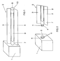
- FIG. 1 of the present application shows an inventive lighting system with an electronic ballast 1, which is shown here as a simple cuboid.
- the figure shows only the housing of the ballast 1, which contains the otherwise known per se circuit parts of a ballast for operating a dielectrically impeded discharge lamp. This may in particular be a class E converter.
- FIG. 1 shows that in the rear region of the right side of the ballast 1 in FIG. 1, a substantially line-shaped dielectrically impeded discharge lamp 2 with two laterally projecting shielding surfaces 3 is inserted.
- Figure 2 shows a detail of the ballast 1 and the lamp 2 of Figure 1 is a situation in which the lamp 2 is pulled out of the ballast 1.
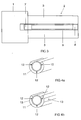
- FIG. 3 shows a plan view of the situation from FIG. 1.
- FIG. 2 It can be seen in FIG. 2 that a base 7 of the tubular lamp 2 projects beyond the shielding surfaces 3 to the left and this cylindrical protruding one Base 7 has three further reaching axially extending electrode ends 4. Further, Figure 2 indicates that the ballast 1 in its right side surface of the otherwise cuboidal housing shape has a matching receptacle receptacle 5 with therein provided female connector elements 6 for the mentioned axial electrode ends 4 of the discharge lamp 2.
- the axial electrode ends 4 are left-hand ends of round-rod-shaped electrodes of the lamp 2 in FIGS. 1 to 3, to which reference will be made in greater detail with reference to FIGS. 4 to 9. These electrode ends are inserted according to FIG. 2 together with the base 7 of the discharge lamp 2 projecting beyond the shield surfaces 3 into the described socket 5 with the plug connection elements 6. As a result, as shown in FIGS. 1 and 3, the lamp 2 is not only electrically connected to the ballast 1, but moreover is also firmly mounted on it. The ballast 1 thus serves as a lamp holder. A flexible cable between the lamp 2 and ballast 1 can therefore be omitted.
- the part of the lamp 2 extending beyond the shielding surfaces 3 is a plastic base 7 which, together with a second base 8 recognizable in FIGS. 1 and 3, is a tubular glass discharge vessel 9 in a shielding plate having the shielding surfaces 3 and described in more detail below 10 stops.
- the shielding plate 10 is electrically conductively connected to the shielding surfaces 3 with the metallic housing of the ballast 1. This can be done for example by a small pin, not shown in Figures 1 and 2, which rests on the outer periphery of the base 7 and is inserted with this in the socket 5.
- the shielding plate 10 is insulated with respect to the electrodes with the ends 4 via an insulation layer (not shown here but shown in FIG. 4). This is a plastic layer. This plastic insulation lies in the visible in Figures 1 - 3 part of the discharge vessel 9 between the screening surfaces 3, namely the aperture for light emission, not in front.
- the shielding plate 10 forms with the sockets 7 and 8 a sleeve.
- FIG. 4a shows a variant of the mentioned plastic insulation, in the form of a base 11 extending over the lamp length, and otherwise electrode ends 12, which for one do not extend beyond the base 11, and which for the other have tubular shapes. These are female plug connection elements at the electrode ends in contrast to the male connector elements in Figure 2. Accordingly, a not shown complementary ballast male connector elements in a socket comparable to the socket 5 of Figure 2.
- the electrodes are inserted into matching recesses of the base 11 and are held by him form-fitting manner on the discharge vessel.
- the pedestal 11 runs over the lamp length and merges into the pedestal (8 in Figures 1 and 3) at the opposite end of the lamp. He is biased by the shield 10 against the discharge vessel 9 and holds it without further action.
- the discharge vessel 9 is thus a simple gas-filled tube with inner phosphor and reflection layers.
- the insulating layer between the electrodes and the shielding plate 10 is formed at the same time as a base corresponding to the base 7 of Figure 2, so the socket does not engage around the entire circumference of the discharge vessel end around.
- FIG. 4b shows a variant of FIG. 4a in which additional flattenings 13 are provided on the lateral regions of the base 11. These Flattened portions 13 are provided in complementary form on a shielding plate 10 (not illustrated here) corresponding to FIGS. 1-3, so that a correct alignment of the aperture with the shielding surfaces 3 can already be achieved.
- the base 7 of Figure 2 may also be configured so that it specifies only at the ends of the discharge vessel 9 a corresponding Abstandsjustage to the shielding plate 10 and the insulation in the axial intermediate region is only loosely inserted.
- the plug connection between the discharge lamp 2 and the ballast 1 shown in FIGS. 1-3 is not obligatory in the invention. Trained as plug-in elements electrode ends can be useful without this feature, for example, if instead of the socket 5 of the ballast 1, a corresponding female connector head of a connecting cable is provided to the electrode ends and optionally similar to the socket 5 to the base 7 and the discharge vessel 9 fits.
- FIGS. 5-9 show some variants of the discharge lamps according to FIGS. 1-4b.
- FIG. 5 instead of three electrodes (or electrode ends) 4, as in FIG. 2, only two electrodes 4 are provided here. Both variants are possible. Occasionally, three electrodes are chosen for better light output. For the present invention, these differences are not of particular concern.
- the opening angle between the screen surfaces 3, so the wing-like ends of the sleeve 10 is chosen here slightly smaller. However, this opening angle is still so great that it does not appreciably obstruct the actual light emission from the aperture in the upper region of the section shown in FIG. Nevertheless, these screen surfaces 3 serve to improve the electromagnetic shielding in the lateral direction by leakage fields emerging from the aperture.
- FIG. 5 illustrates the aperture in that a phosphor layer 14 is shown there, which is interrupted in the region of the aperture.
- FIG. 6 again shows three electrodes 4, but the essential difference consists in the fact that the shield surfaces 3 'from FIG. 6 are supplemented here by inwardly angled parts and thus limit an even narrower opening angle. This is still significantly larger than the aperture angle of the aperture relative to the center of the circle of the discharge vessel. However, since also the edge regions of the phosphor layer 14 emit light, the outermost regions of the light emission are already dimmed. The shielding effect is, however, improved accordingly.
- FIG. 1 has already made clear that the shielding plate 10 not only serves to hold the electrodes on the discharge vessel 9, but also stabilizes the assembly of the entire discharge lamp 2 on the ballast 1.
- the shielding surfaces 3 can also be mounted separately, for example, clamped to the ballast 1, plugged or screwed. Incidentally, they can also have an assembly function with respect to components other than the ballast housing.
- FIG. 7 shows a further variant of FIG. 5 with a further narrowed opening angle of the shielding surfaces 3, but here with straight shielding surfaces 3.
- the base 7 according to FIG. 2 runs around the entire circumference of the discharge vessel 9 and does not save, as in FIG , the aperture off.
- the base 7 is only attached to the outermost edge, this does not disturb the light emission or hardly.
- Figure 8 differs just by this latter feature of Figure 7. Again, the aperture is recessed. It is therefore a base 11 according to FIG. 4.
- FIG. 9 differs from FIG. 8 by an additional shielding part 15 in the opening angle of both the shielding surfaces 3 and the aperture.
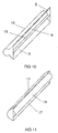
- This is configured radially in the illustrated cross-section and otherwise planar and in the perspective view in Figure 10 better visible. It slightly reduces the light emission through the aperture, but additionally improves the electromagnetic shielding in the light emission direction.
- Such a part 15 may be a cost effective alternative or additional measure to a transparent conductive coating of the aperture, as shown in the already cited EP-font. For clarity, the details of the connector in Figure 10 are omitted.
- FIG. 11 shows, in a representation similar to FIG. 10, a variant of the design of the shielding plate 10.
- the shielding plate 10 with the shielding surfaces when viewed in section basically consists of two concentric semicircles 16 and 17 with substantially different diameters around the center of the circle of the section through the discharge vessel 9
- the semicircles 16, 17 face each other with their openings.
- the smaller of the semicircles 16 also shows a significantly greater distance from the discharge vessel 9, which is not shown here.
- the smaller semicircle 16 serves as a reflector, reflecting the light radiated from the aperture into it (that is, to the right in FIG. 11) into the larger semicircle 17, which in turn reflects the light out of the cuff.
- This variant offers a significantly poorer light output than the previous examples, but shows a much better EMC shielding.
- FIG. 12 corresponds in the illustration to FIGS. 5 to 9, but shows an exemplary embodiment without shielding plate.
- the sleeve is designed as a positive and non-positive plastic sleeve 18, which has corresponding mold recesses for the electrodes 4 and thus holds them on the discharge vessel 9.
- the shielding effect explained above is omitted here or could be given by a shield plate without screens; however, the other benefits of the cuff are also given.
- FIG. 13 shows another form 19 of such a sleeve, which is also considerably more solid. It could for example be used for mounting in a corner situation and has matching inclined surfaces with each other right angle, which are designated 20.
- FIGS. 14 and 15 show similar variants as in FIG. 13, but with an almost square cross-section of the sleeve 21 and with two in FIG. 14 and three electrodes 4 in FIG.
- FIG. 16 shows a two-part variant of a cuff.
- Both parts 22a and 22b together result in a similar cross-sectional shape as the sleeve 21 of Figures 14 and 15, but neither of the two halves already produces a positive connection or adhesion.
- the two parts are thus applied from left and right to the discharge vessel 9 and then clipped together via a preferably non-detachable clip connection in the slot 23 and so brought opposite to the discharge vessel 9 to bias.
- other cross-sectional shapes can be produced with comparable embodiments, in particular those as in the other embodiments.
- FIG. 16 also illustrates that the electrodes, designated here by 24, can also have other than round cross-sectional shapes.
Landscapes
- Physics & Mathematics (AREA)
- Engineering & Computer Science (AREA)
- Plasma & Fusion (AREA)
- Electromagnetism (AREA)
- Common Detailed Techniques For Electron Tubes Or Discharge Tubes (AREA)
- Fastening Of Light Sources Or Lamp Holders (AREA)
- Discharge Lamps And Accessories Thereof (AREA)
- Connecting Device With Holders (AREA)
- Arrangement Of Elements, Cooling, Sealing, Or The Like Of Lighting Devices (AREA)
Applications Claiming Priority (1)
| Application Number | Priority Date | Filing Date | Title |
|---|---|---|---|
| DE102004047376A DE102004047376A1 (de) | 2004-09-29 | 2004-09-29 | Dielektrisch behinderte Entladungslampe mit steckbaren Elektroden |
Publications (2)
| Publication Number | Publication Date |
|---|---|
| EP1643537A2 true EP1643537A2 (fr) | 2006-04-05 |
| EP1643537A3 EP1643537A3 (fr) | 2006-10-18 |
Family
ID=35586110
Family Applications (1)
| Application Number | Title | Priority Date | Filing Date |
|---|---|---|---|
| EP05018817A Withdrawn EP1643537A3 (fr) | 2004-09-29 | 2005-08-30 | Lampe à décharge à barrière diélectrique avec électrodes enfichables |
Country Status (8)
| Country | Link |
|---|---|
| US (1) | US7573201B2 (fr) |
| EP (1) | EP1643537A3 (fr) |
| JP (1) | JP2006108094A (fr) |
| KR (1) | KR20060051855A (fr) |
| CN (1) | CN1755892B (fr) |
| CA (1) | CA2521208A1 (fr) |
| DE (1) | DE102004047376A1 (fr) |
| TW (1) | TW200616005A (fr) |
Families Citing this family (5)
| Publication number | Priority date | Publication date | Assignee | Title |
|---|---|---|---|---|
| DE102004047373A1 (de) * | 2004-09-29 | 2006-04-06 | Patent-Treuhand-Gesellschaft für elektrische Glühlampen mbH | Beleuchtungssystem mit dielektrisch behinderter Entladungslampe und zugehörigem Vorschaltgerät |
| DE102004047375A1 (de) * | 2004-09-29 | 2006-04-06 | Patent-Treuhand-Gesellschaft für elektrische Glühlampen mbH | Dielektrische behinderte Entladungslampe mit Manschette |
| GB2478717A (en) * | 2010-03-15 | 2011-09-21 | Gew | Lamp housing for ink curing apparatus |
| JP5218877B6 (ja) * | 2010-03-18 | 2018-06-27 | 株式会社Gsユアサ | 誘電体バリア放電ランプおよびランプユニット |
| KR20140064270A (ko) * | 2012-11-20 | 2014-05-28 | 에스케이하이닉스 주식회사 | 반도체 메모리 장치 |
Family Cites Families (38)
| Publication number | Priority date | Publication date | Assignee | Title |
|---|---|---|---|---|
| US3652848A (en) | 1968-08-21 | 1972-03-28 | Jack V Miller | Fluorescent lighting fixtures |
| CH676168A5 (fr) | 1988-10-10 | 1990-12-14 | Asea Brown Boveri | |
| EP0517929B1 (fr) | 1991-06-01 | 1995-03-15 | Heraeus Noblelight GmbH | Dispositif d'irradiation avec un radiateur à haute puissance |
| ZA927756B (en) | 1991-10-09 | 1993-07-12 | Kelmas Co Sa | Device applicable to fluorescent tubes to reduce the energy consumption without varying the luminous flow. |
| US5325024A (en) * | 1992-10-16 | 1994-06-28 | Gte Products Corporation | Light source including parallel driven low pressure RF fluorescent lamps |
| JPH07319013A (ja) | 1994-05-24 | 1995-12-08 | Olympus Optical Co Ltd | 閃光装置の光学パネル |
| JPH09120704A (ja) | 1995-10-26 | 1997-05-06 | Nec Home Electron Ltd | 放電灯装置及び原稿照射装置 |
| KR19990028248A (ko) | 1996-04-19 | 1999-04-15 | 엠. 제이. 엠. 반캄 | 무전극 저압방전램프 |
| PL331378A1 (en) | 1996-05-31 | 1999-07-05 | Fusion Lighting | Multiple-reflection electrode-free sulphur- or selenium-filled lamp and method of generating radiation using such lamp |
| US6333509B1 (en) | 1996-07-09 | 2001-12-25 | Lumpp & Consultants | Electromagnetic radiation transmitter/reflector device, apparatus and process implementing such a device |
| JPH10223182A (ja) | 1997-02-10 | 1998-08-21 | Stanley Electric Co Ltd | 蛍光ランプ |
| US5993034A (en) | 1997-02-21 | 1999-11-30 | Valeo Sylvania L.L.C. | Lamp reflector for use with gaseous discharge lighting |
| JPH1186434A (ja) | 1997-09-11 | 1999-03-30 | Sony Corp | 記録装置、記録方法、及びダビング装置 |
| DE19811520C1 (de) | 1998-03-17 | 1999-08-12 | Patent Treuhand Ges Fuer Elektrische Gluehlampen Mbh | Entladungslampe mit dielektrisch behinderten Entladungen |
| DE19817475B4 (de) | 1998-04-20 | 2004-04-15 | Patent-Treuhand-Gesellschaft für elektrische Glühlampen mbH | Entladungslampe mit dielektrisch behinderten Elektroden sowie Beleuchtungssystem mit einer solchen Entladungslampe |
| JP3509551B2 (ja) | 1998-04-30 | 2004-03-22 | ウシオ電機株式会社 | 外部電極型放電ランプによる光源装置 |
| DE19900870A1 (de) * | 1999-01-12 | 2000-08-03 | Walter Holzer | Gerade Leuchtstofflampe mit Vorschaltgerät |
| DE19900889B4 (de) | 1999-01-12 | 2004-04-15 | Suresh Hiralal Shah | Bausatz zum Umrüsten von Leuchten mit geraden, beidseitig gesockelten Leuchtstofflampen, von induktivem auf elektronischen Betrieb |
| JP2000285867A (ja) | 1999-03-31 | 2000-10-13 | Toshiba Lighting & Technology Corp | 放電ランプ装置及び照明装置 |
| DE19933405A1 (de) | 1999-07-21 | 2001-03-29 | Patent Treuhand Ges Fuer Elektrische Gluehlampen Mbh | Längliche Lichtquelle |
| JP2001155690A (ja) | 1999-11-30 | 2001-06-08 | Toshiba Lighting & Technology Corp | 光触媒機構、光触媒脱臭器および光触媒脱臭機能付装置 |
| US6507028B2 (en) | 1999-12-17 | 2003-01-14 | Trojan Technologies, Inc. | Radiation source module |
| DE10007130C1 (de) | 2000-02-17 | 2001-05-17 | Siemens Ag | Verfahren und Vorrichtung zur plasmainduzierten Minderung der Rußemission von Dieselmotoren |
| JP2001319510A (ja) | 2000-05-11 | 2001-11-16 | Ushio Inc | 誘電体バリア放電ランプ装置 |
| US6531824B1 (en) | 2000-09-21 | 2003-03-11 | Technical Consumer Products, Inc | Universal electronic plug-in replaceable fluorescent lamp ballast and adapter |
| DE10048986A1 (de) | 2000-09-27 | 2002-04-11 | Patent Treuhand Ges Fuer Elektrische Gluehlampen Mbh | Dielektrische Barrieren-Entladungslampe |
| DE10111447A1 (de) | 2001-03-09 | 2002-09-12 | Werner Schroeder | Belüftungsanlage für den Innenraum eines Fahrzeugs |
| JP3622721B2 (ja) | 2001-12-04 | 2005-02-23 | ウシオ電機株式会社 | 蛍光ランプ |
| EP1329944A3 (fr) | 2001-12-14 | 2009-11-04 | Patent-Treuhand-Gesellschaft für elektrische Glühlampen mbH | Lampe à décharge à barrière diélectrique avec aide à l'allumage |
| CN2600916Y (zh) * | 2001-12-28 | 2004-01-21 | 徐晓明 | 荧光灯 |
| DE10213195A1 (de) | 2002-03-25 | 2003-10-16 | Behr Gmbh & Co | Luftbehandlungsanlage für ein Fahrzeug |
| JP3889987B2 (ja) | 2002-04-19 | 2007-03-07 | パナソニック フォト・ライティング 株式会社 | 放電灯装置及びバックライト |
| JP3781719B2 (ja) | 2002-11-15 | 2006-05-31 | Necライティング株式会社 | 紫外面光源及びその製造方法並びに蛍光トランスイルミネーター |
| GB2399216B (en) | 2003-03-06 | 2007-05-09 | Quay Technologies Ltd | Ultraviolet light source |
| US6787782B1 (en) | 2003-04-23 | 2004-09-07 | B/E Aerospace, Inc. | Ultraviolet-light vehicle air cleaning system |
| DE102004047374A1 (de) * | 2004-09-29 | 2006-04-06 | Patent-Treuhand-Gesellschaft für elektrische Glühlampen mbH | Dielektrisch behinderte Entladungslampe mit elektrischer Abschirmung |
| DE102004047373A1 (de) | 2004-09-29 | 2006-04-06 | Patent-Treuhand-Gesellschaft für elektrische Glühlampen mbH | Beleuchtungssystem mit dielektrisch behinderter Entladungslampe und zugehörigem Vorschaltgerät |
| DE102004047375A1 (de) | 2004-09-29 | 2006-04-06 | Patent-Treuhand-Gesellschaft für elektrische Glühlampen mbH | Dielektrische behinderte Entladungslampe mit Manschette |
-
2004
- 2004-09-29 DE DE102004047376A patent/DE102004047376A1/de not_active Withdrawn
-
2005
- 2005-08-30 EP EP05018817A patent/EP1643537A3/fr not_active Withdrawn
- 2005-09-15 US US11/226,411 patent/US7573201B2/en not_active Expired - Fee Related
- 2005-09-23 TW TW094133017A patent/TW200616005A/zh unknown
- 2005-09-26 CA CA002521208A patent/CA2521208A1/fr not_active Abandoned
- 2005-09-29 CN CN2005101076615A patent/CN1755892B/zh not_active Expired - Fee Related
- 2005-09-29 KR KR1020050091377A patent/KR20060051855A/ko not_active Withdrawn
- 2005-09-29 JP JP2005284870A patent/JP2006108094A/ja active Pending
Also Published As
| Publication number | Publication date |
|---|---|
| JP2006108094A (ja) | 2006-04-20 |
| US7573201B2 (en) | 2009-08-11 |
| CA2521208A1 (fr) | 2006-03-29 |
| DE102004047376A1 (de) | 2006-04-06 |
| CN1755892A (zh) | 2006-04-05 |
| CN1755892B (zh) | 2010-06-16 |
| US20060066242A1 (en) | 2006-03-30 |
| KR20060051855A (ko) | 2006-05-19 |
| EP1643537A3 (fr) | 2006-10-18 |
| TW200616005A (en) | 2006-05-16 |
Similar Documents
| Publication | Publication Date | Title |
|---|---|---|
| DE102012203886A1 (de) | Leuchtdiodenlampe und Verfahren zum Fertigen einer Leuchtdiodenlampe | |
| DE3632810A1 (de) | Leuchtstofflampenvorrichtung | |
| EP1643538B1 (fr) | Lampe à décharge à barrière dielectrique avec blindage électrique | |
| EP2731201A1 (fr) | Connecteur électrique et procede de montage de pièces d'un connecteur électrique | |
| EP1506567B1 (fr) | Lampe a decharge a barriere dielectrique comprenant un socle | |
| EP1646071B1 (fr) | Système d'illumination avec une lampe à décharge à barrière diélectrique et générateur de fréquence associé | |
| EP1643537A2 (fr) | Lampe à décharge à barrière diélectrique avec électrodes enfichables | |
| DE60008719T2 (de) | Eingangs/ausgangssteckverbinderanordnung mit erdungsanordnung für abgeschirmte kabel und verfahren zur herstellung und zum zusammenbau eines solchen steckverbinders | |
| EP1334510B1 (fr) | Lampe a decharge a barriere dielectrique | |
| EP1643539A1 (fr) | Lampe à barrière diélectrique avec un clip | |
| EP1115998B1 (fr) | Source lumineuse allongee | |
| EP0854496A2 (fr) | Lampe compacte à décharge basse pression | |
| DE10133326A1 (de) | Dielektrische Barrieren-Entladungslampe mit Zündhilfe | |
| EP0854497A2 (fr) | Lampe compacte à décharge basse pression | |
| DE10313956A1 (de) | Koppelelement für längliche Lampen und Beleuchtungssystem mit diesem Koppelelement | |
| DE10312720A1 (de) | Dielektrische Barriere-Entladungslampe mit Quetschdichtung | |
| DE69300300T2 (de) | Kittlos gesockelte gasentladungslampe mit rechtwinkliger halterung. | |
| DE102006037122B3 (de) | Medizinische Elektrode mit wenigstens zwei Polen und einem Stecker und deren Verwendung | |
| EP0923105B1 (fr) | Lampe à décharge à basse pression de type compact | |
| DE60037175T2 (de) | Niederdruck gasentladungslampe | |
| DE3439137A1 (de) | Einseitig gesockelte quecksilberdampfniederdruckentladungslampe | |
| EP0459170B1 (fr) | Douille pour une ampoule miniature | |
| EP2101554B1 (fr) | Boîtier doté d'une platine conductrice | |
| EP1366545A1 (fr) | Projecteur plat comportant un systeme de contact | |
| DE19805258C2 (de) | Lampenfassung |
Legal Events
| Date | Code | Title | Description |
|---|---|---|---|
| PUAI | Public reference made under article 153(3) epc to a published international application that has entered the european phase |
Free format text: ORIGINAL CODE: 0009012 |
|
| AK | Designated contracting states |
Kind code of ref document: A2 Designated state(s): AT BE BG CH CY CZ DE DK EE ES FI FR GB GR HU IE IS IT LI LT LU LV MC NL PL PT RO SE SI SK TR |
|
| AX | Request for extension of the european patent |
Extension state: AL BA HR MK YU |
|
| PUAL | Search report despatched |
Free format text: ORIGINAL CODE: 0009013 |
|
| AK | Designated contracting states |
Kind code of ref document: A3 Designated state(s): AT BE BG CH CY CZ DE DK EE ES FI FR GB GR HU IE IS IT LI LT LU LV MC NL PL PT RO SE SI SK TR |
|
| AX | Request for extension of the european patent |
Extension state: AL BA HR MK YU |
|
| 17P | Request for examination filed |
Effective date: 20061107 |
|
| 17Q | First examination report despatched |
Effective date: 20061213 |
|
| AKX | Designation fees paid |
Designated state(s): AT DE FR GB HU |
|
| GRAP | Despatch of communication of intention to grant a patent |
Free format text: ORIGINAL CODE: EPIDOSNIGR1 |
|
| STAA | Information on the status of an ep patent application or granted ep patent |
Free format text: STATUS: THE APPLICATION IS DEEMED TO BE WITHDRAWN |
|
| 18D | Application deemed to be withdrawn |
Effective date: 20120831 |