EP1643570B1 - Kombinations-batterie - Google Patents
Kombinations-batterie Download PDFInfo
- Publication number
- EP1643570B1 EP1643570B1 EP20040734414 EP04734414A EP1643570B1 EP 1643570 B1 EP1643570 B1 EP 1643570B1 EP 20040734414 EP20040734414 EP 20040734414 EP 04734414 A EP04734414 A EP 04734414A EP 1643570 B1 EP1643570 B1 EP 1643570B1
- Authority
- EP
- European Patent Office
- Prior art keywords
- cells
- battery pack
- side faces
- pack according
- cooling medium
- Prior art date
- Legal status (The legal status is an assumption and is not a legal conclusion. Google has not performed a legal analysis and makes no representation as to the accuracy of the status listed.)
- Expired - Lifetime
Links
- 230000000452 restraining effect Effects 0.000 claims abstract description 11
- 239000002826 coolant Substances 0.000 claims description 44
- 125000006850 spacer group Chemical group 0.000 claims description 36
- 230000017525 heat dissipation Effects 0.000 claims description 19
- 239000002184 metal Substances 0.000 claims description 12
- 239000011810 insulating material Substances 0.000 claims description 5
- 238000010248 power generation Methods 0.000 abstract 1
- 238000001816 cooling Methods 0.000 description 9
- 230000009467 reduction Effects 0.000 description 6
- 238000003466 welding Methods 0.000 description 5
- 230000006866 deterioration Effects 0.000 description 4
- 230000000694 effects Effects 0.000 description 4
- 238000009413 insulation Methods 0.000 description 4
- 230000003014 reinforcing effect Effects 0.000 description 4
- 239000011324 bead Substances 0.000 description 3
- 230000008878 coupling Effects 0.000 description 3
- 238000010168 coupling process Methods 0.000 description 3
- 238000005859 coupling reaction Methods 0.000 description 3
- 238000000034 method Methods 0.000 description 3
- 230000000717 retained effect Effects 0.000 description 3
- 229920003002 synthetic resin Polymers 0.000 description 3
- 239000000057 synthetic resin Substances 0.000 description 3
- 238000009826 distribution Methods 0.000 description 2
- 238000010292 electrical insulation Methods 0.000 description 2
- 238000010894 electron beam technology Methods 0.000 description 2
- 238000009434 installation Methods 0.000 description 2
- 229910000831 Steel Inorganic materials 0.000 description 1
- 230000015572 biosynthetic process Effects 0.000 description 1
- 238000007796 conventional method Methods 0.000 description 1
- 239000000446 fuel Substances 0.000 description 1
- 238000005304 joining Methods 0.000 description 1
- 239000011244 liquid electrolyte Substances 0.000 description 1
- 238000004519 manufacturing process Methods 0.000 description 1
- 239000000463 material Substances 0.000 description 1
- 230000013011 mating Effects 0.000 description 1
- 238000000465 moulding Methods 0.000 description 1
- 238000005549 size reduction Methods 0.000 description 1
- 239000010959 steel Substances 0.000 description 1
Images



Classifications
-
- H—ELECTRICITY
- H01—ELECTRIC ELEMENTS
- H01M—PROCESSES OR MEANS, e.g. BATTERIES, FOR THE DIRECT CONVERSION OF CHEMICAL ENERGY INTO ELECTRICAL ENERGY
- H01M10/00—Secondary cells; Manufacture thereof
- H01M10/60—Heating or cooling; Temperature control
- H01M10/61—Types of temperature control
- H01M10/613—Cooling or keeping cold
-
- H—ELECTRICITY
- H01—ELECTRIC ELEMENTS
- H01M—PROCESSES OR MEANS, e.g. BATTERIES, FOR THE DIRECT CONVERSION OF CHEMICAL ENERGY INTO ELECTRICAL ENERGY
- H01M10/00—Secondary cells; Manufacture thereof
- H01M10/60—Heating or cooling; Temperature control
- H01M10/62—Heating or cooling; Temperature control specially adapted for specific applications
- H01M10/625—Vehicles
-
- H—ELECTRICITY
- H01—ELECTRIC ELEMENTS
- H01M—PROCESSES OR MEANS, e.g. BATTERIES, FOR THE DIRECT CONVERSION OF CHEMICAL ENERGY INTO ELECTRICAL ENERGY
- H01M10/00—Secondary cells; Manufacture thereof
- H01M10/60—Heating or cooling; Temperature control
- H01M10/64—Heating or cooling; Temperature control characterised by the shape of the cells
- H01M10/647—Prismatic or flat cells, e.g. pouch cells
-
- H—ELECTRICITY
- H01—ELECTRIC ELEMENTS
- H01M—PROCESSES OR MEANS, e.g. BATTERIES, FOR THE DIRECT CONVERSION OF CHEMICAL ENERGY INTO ELECTRICAL ENERGY
- H01M10/00—Secondary cells; Manufacture thereof
- H01M10/60—Heating or cooling; Temperature control
- H01M10/65—Means for temperature control structurally associated with the cells
- H01M10/655—Solid structures for heat exchange or heat conduction
- H01M10/6551—Surfaces specially adapted for heat dissipation or radiation, e.g. fins or coatings
-
- H—ELECTRICITY
- H01—ELECTRIC ELEMENTS
- H01M—PROCESSES OR MEANS, e.g. BATTERIES, FOR THE DIRECT CONVERSION OF CHEMICAL ENERGY INTO ELECTRICAL ENERGY
- H01M10/00—Secondary cells; Manufacture thereof
- H01M10/60—Heating or cooling; Temperature control
- H01M10/65—Means for temperature control structurally associated with the cells
- H01M10/655—Solid structures for heat exchange or heat conduction
- H01M10/6556—Solid parts with flow channel passages or pipes for heat exchange
- H01M10/6557—Solid parts with flow channel passages or pipes for heat exchange arranged between the cells
-
- H—ELECTRICITY
- H01—ELECTRIC ELEMENTS
- H01M—PROCESSES OR MEANS, e.g. BATTERIES, FOR THE DIRECT CONVERSION OF CHEMICAL ENERGY INTO ELECTRICAL ENERGY
- H01M50/00—Constructional details or processes of manufacture of the non-active parts of electrochemical cells other than fuel cells, e.g. hybrid cells
- H01M50/20—Mountings; Secondary casings or frames; Racks, modules or packs; Suspension devices; Shock absorbers; Transport or carrying devices; Holders
- H01M50/204—Racks, modules or packs for multiple batteries or multiple cells
- H01M50/207—Racks, modules or packs for multiple batteries or multiple cells characterised by their shape
- H01M50/209—Racks, modules or packs for multiple batteries or multiple cells characterised by their shape adapted for prismatic or rectangular cells
-
- H—ELECTRICITY
- H01—ELECTRIC ELEMENTS
- H01M—PROCESSES OR MEANS, e.g. BATTERIES, FOR THE DIRECT CONVERSION OF CHEMICAL ENERGY INTO ELECTRICAL ENERGY
- H01M50/00—Constructional details or processes of manufacture of the non-active parts of electrochemical cells other than fuel cells, e.g. hybrid cells
- H01M50/20—Mountings; Secondary casings or frames; Racks, modules or packs; Suspension devices; Shock absorbers; Transport or carrying devices; Holders
- H01M50/262—Mountings; Secondary casings or frames; Racks, modules or packs; Suspension devices; Shock absorbers; Transport or carrying devices; Holders with fastening means, e.g. locks
-
- H—ELECTRICITY
- H01—ELECTRIC ELEMENTS
- H01M—PROCESSES OR MEANS, e.g. BATTERIES, FOR THE DIRECT CONVERSION OF CHEMICAL ENERGY INTO ELECTRICAL ENERGY
- H01M50/00—Constructional details or processes of manufacture of the non-active parts of electrochemical cells other than fuel cells, e.g. hybrid cells
- H01M50/20—Mountings; Secondary casings or frames; Racks, modules or packs; Suspension devices; Shock absorbers; Transport or carrying devices; Holders
- H01M50/289—Mountings; Secondary casings or frames; Racks, modules or packs; Suspension devices; Shock absorbers; Transport or carrying devices; Holders characterised by spacing elements or positioning means within frames, racks or packs
- H01M50/291—Mountings; Secondary casings or frames; Racks, modules or packs; Suspension devices; Shock absorbers; Transport or carrying devices; Holders characterised by spacing elements or positioning means within frames, racks or packs characterised by their shape
-
- Y—GENERAL TAGGING OF NEW TECHNOLOGICAL DEVELOPMENTS; GENERAL TAGGING OF CROSS-SECTIONAL TECHNOLOGIES SPANNING OVER SEVERAL SECTIONS OF THE IPC; TECHNICAL SUBJECTS COVERED BY FORMER USPC CROSS-REFERENCE ART COLLECTIONS [XRACs] AND DIGESTS
- Y02—TECHNOLOGIES OR APPLICATIONS FOR MITIGATION OR ADAPTATION AGAINST CLIMATE CHANGE
- Y02E—REDUCTION OF GREENHOUSE GAS [GHG] EMISSIONS, RELATED TO ENERGY GENERATION, TRANSMISSION OR DISTRIBUTION
- Y02E60/00—Enabling technologies; Technologies with a potential or indirect contribution to GHG emissions mitigation
- Y02E60/10—Energy storage using batteries
Definitions
- the present invention relates to a battery pack formed of a plurality of parallel arranged battery modules, each battery module consisting of a plurality of series-connected cells.
- the end plates as a restraining tool, need to have a rigidity that is high enough to withstand the internal pressure of the prismatic cells or the expansion of battery electrode plates, and in order to increase the rigidity, the end plates tend to be heavy and large, causing an increase in the weight and cost of the battery pack.
- Document EP 1 178 558 discloses a battery pack with connectors extending between cells but not coupled to the end plates.
- a battery pack according to claim 1 comprising: a plurality of parallel arranged battery modules, each battery module consisting of a plurality of cells formed by encasing elements for electromotive force in prismatic cases, the cells being electrically connected in series by a connection terminal protruded on one of opposing side faces thereof and coupled together in one piece with gaps formed between the opposing side faces thereof; and a restraining tool having end plates arranged at both ends in al alignment direction of the battery modules and connecting members, and the connecting members are extending through the gaps between two given cells at both ends of the parallel arranged battery modules and both ends of the connecting members are coupled to the end plates.
- the parallel arranged battery modules may be provided components for forming cooling medium passages between side faces of the cells.
- the cells of the battery modules are then cooled effectively from their side faces by the cooling medium flowing through the cooling medium passages, whereby deterioration of battery characteristics due to a temperature rise is prevented.
- Such components for forming cooling medium passages should preferably be disposed between the long side faces of the cells to achieve high cooling effect.
- the components forming the cooling medium passages may be provided on the cases of the cells, but should preferably be formed of separate spacer portions independently of the battery modules so that they are made of a suitably selected material.
- the cell case configuration is then made simple and the cells are produced at lower cost, leading to an overall cost reduction.
- the cell cases are preferably made of a metal and the components forming the cooling medium passages are insulating spacer portions provided independently of the battery modules, so that insulation between the battery modules consisting of cells encased in metal cases is achieved by interposing the insulating spacer portions therebetween.
- the spacer portions may have holder portions that fit in the gaps between the cells for positioning the cells, so that relative positions of the cells of each battery module are restricted by the spacer portions, whereby the battery pack is rigidly assembled and safety features of the battery pack under severe use conditions such as when mounted on a vehicle are improved.
- connection terminals of the cells are preferably protruded on short side faces of the cell cases, and the cooling medium passages are formed between the long side faces of the cells, so as to achieve effective cooling of the cells from their long side faces and to prevent deterioration of battery characteristics due to a temperature rise.
- the holder portions of the holders should preferably engage with generally half or less of the width of the short side faces of the cells to securely retain the cells by the holders.
- the cell cases are preferably made of a metal and the holders are made of an insulating material, so that insulation between the battery modules consisting of cells encased in metal cases is achieved.
- a battery pack includes a plurality of parallel arranged battery modules, each battery module consisting of a plurality of cells formed by encasing elements for electromotive force in prismatic cases, the cells being electrically connected with each other in series by connection terminals protruded on their side faces, holders for the battery modules disposed between parallel arranged adjacent battery modules, end plates arranged at both ends in the alignment direction of the battery modules, and connecting members extending through the gaps at both ends of the battery modules and between two given cells and coupling both end plates together, wherein each holder includes a spacer portion forming a cooling medium passage between side faces of the cells and holder portions provided on both sides of the spacer portion at locations corresponding to both sides of each cell for engaging with and retaining the cells.
- the same effects as the battery pack according to the first aspect of the invention described above are achieved. Moreover, because the battery module with the holder retaining each of the cells is obtained by fitting the battery module in the holder or by connecting the connection terminals using the holder to hold the cells, the battery pack is assembled with good productivity simply by arranging these holders in parallel, with the end plates provided at both ends, and by coupling them together with the connecting members.
- connection terminals of the cells are preferably protruded on short side faces of the cell cases, and the cooling medium passages are formed between the long side faces of the cells, so as to achieve effective cooling of the cells from their long side faces and to prevent deterioration of battery characteristics due to a temperature rise.
- the holder portions of the holders should preferably engage with generally half or less of the width of the short side faces of the cells to securely retain the cells by the holders.
- the cell cases are preferably made of a metal and the holders are made of an insulating material, so that insulation between the battery modules consisting of cells encased in metal cases is achieved by interposing the insulating spacer portions therebetween.
- the holder may include support portions at both ends, which are placed on support members, at least one of the support portions being provided with a fixing bolt hole or screw hole, so that the battery pack is readily and firmly installed by placing the support portions at both ends of the holders on the support members and by fastening with bolts.
- the support portions at both ends of the holders may be formed with an engaging protrusion on one side and an engaging recess on the other side in which the engaging protrusion fits.
- the holders When connecting the battery modules sequentially in series to form the battery pack, the holders are arranged parallel in alternate directions and the connection terminals at both ends of adjacent battery modules are connected. In this process, only one end of the holder needs to be fixed using a bolt, because the other end of the holder is fixedly retained between the support portions of the holders on both sides by the engagement between the engaging protrusions and engaging recesses.
- the number of the bolts is reduced by half, leading to weight and cost reductions.
- the holder portions of the holders may include support projections on the top and the bottom, which are engaged with an upper case and a lower case covering the battery pack.
- the battery modules are thus supported by the upper and lower cases covering the battery pack via the holders, and, such support projections form spaces for supply and discharge of cooling medium between the top of the holders and the upper case and between the bottom of the holders and the lower case.
- the connecting members are preferably arranged on both sides of each of the cells of the battery modules, so that the end plates are restrained at both sides of each cell, whereby the rigidity of the end plates is made lower, leading to weight and size reductions.
- Heat dissipation fins forming the cooling medium passages may be provided on the long side faces of the cells to enhance the cell cooling performance.
- the spacer portions may have projections that abut on the long side faces of the cells to form the cooling medium passages, so that cooling medium passages are formed between the battery modules with a simple and inexpensive configuration.
- Heat dissipation fins facing the cooling medium passages may be provided on the long side faces of the cells to enhance the cell cooling performance.
- Such heat dissipation fins may be fixed on the long side faces of the cells, but also may be resiliently pressed against the long side faces of the cells by pressure applied from the spacer portions forming the cooling medium passages, so that desired cooling effect is achieved without the process of fixing the heat dissipation fins on the long side faces of the cells.
- Fig. 1 denotes a battery pack used as a drive power source of electric vehicles including electric vehicles, hybrid vehicles or the like driven by fuel batteries.
- a plurality of (six in the illustrated example) battery modules 2 are arranged in parallel, and end plates 3 are arranged at both ends in the parallel alignment direction of the battery modules 2.
- the end plates 3 are coupled together using a plurality of plate strips or connecting members 4 (three each at nine locations in the illustrated example).
- the battery module 2 consists of a plurality of (eight in the illustrated example) cells 5.
- Each cell 5 is formed by accommodating elements for electromotive force consisting of laminated positive and negative electrode plates with separators interposed therebetween and liquid electrolyte in a prismatic metal case.
- a current collector of one polarity extending from the electrode plates is connected to the case, and the current collector of the other polarity is connected to a pair of connection terminals 6 extending through one short side face of the case in an insulated manner.
- Corresponding connection terminals 7 protrude from the other short side face of the case opposite the short side face formed with the connection terminals 6.
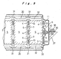
- connection terminals 6 and 7 are coupled together and electrically connected in series with each other by joining the pairs of positive and negative connection terminals 6 and 7 respectively protruded on both short side faces by laser beam welding or electron beam welding to form the battery module 2, as shown in Fig. 9 .
- the pair of connection terminals 6 on the outer short side face at one end of the battery module 2 are joined to both ends of a connection plate 9 formed with a protruding electrode pole 10 in the center by laser beam welding or electron beam welding.
- the holder 11 is a synthetic resin molded component having electrical insulation properties, and includes, as shown in Fig. 4 , a spacer portion 12 that forms cooling medium passages between the long side faces of the cells 5, and holder portions 13 provided on one or both sides of the spacer portion 12 at positions corresponding to both sides of each of the cells 5 for holding the cells 5.
- the holder portions 13 are formed on both sides of the spacer portion 12 in the holders 11 that are arranged between the battery modules 2, while the holder portions are formed on one side in the holders 11 that are arranged between the battery modules 2 and the end plates 3.
- the spacer portion 12 is formed of a relatively thin connection plate 14 extending over the entire surface of the holder 11 and a plurality of appropriately spaced protrusions 15 extending in an up and down direction on both sides of the connection plate 14 such that their top faces abut on the long side faces of the cells 5.
- the cooling medium passages 16 are formed by the space made by these protrusions 15 between the connection plate 14 and the long side faces of the cells 5. The interval between the protrusions 15 is set such that expansion of the long side faces of the cells 5 is prevented effectively.
- corrugated or continuously ridged heat dissipation fins 17 fixed to the long side faces of the cells 5 by welding or the like are arranged, so that heat generated in the cells 5 is efficiently conducted to the cooling medium flowing through the cooling medium passages 16.
- the heat dissipation fins 17 need not necessarily be fixed to the long side faces of the cells 5 and may only make resilient contact therewith by pressure from the connection plate 14, whereby the production cost for the cases of the cells 5 is reduced.
- the holder portions 13 protrude to fit in the gaps 8 between the cells 5 and to engage with generally half or less of the width of the short side faces of the cells 5, as shown in Fig. 3 .
- the holder portions 13 are provided at three locations, in the upper and lower parts of the connection plate 14 and in the middle between the pairs of connection terminals 6 and 7. Through holes 18 are formed in the cross-sectional center of the holder portions 13 for retaining the connecting members 4 extending therethrough.
- the upper and lower holder portions 13 include flanges 19 extending from the upper and lower ends for engaging with the upper and lower end faces of the cells 5.
- the holder portions 13 at both ends of the holder 11 are designed to engage with the outer short side faces and upper and lower end faces of the cells 5 at both ends.
- the holder 11 is provided with support portions 20 in the lower part at both ends.
- the support portion 20 includes an installation surface 21 that is placed on a support member (not shown) in engagement therewith and a fixing screw hole 22 formed by insert-molding a nut member.
- the screw hole 22 may be replaced with a bolt hole.
- the support portions 20 at both ends of the holder 11 respectively include an engaging protrusion 23 on one side and an engaging recess 24 on the other side in which the engaging protrusion 23 fits.
- the end plate 3 is a press-formed thin steel plate and divided in blocks 3a corresponding to each of the cells 5 in the illustrated example.
- Each block 3a is provided with a plurality of reinforcing beads 25 for securing surface strength and rigidity.
- the ends 4a of the connecting member 4 are fitted in sheath portions 26 provided on both sides of each block 3a.
- the sheath portion 26 and the ends 4a of the connecting member 4 are fixed by wedge members 27 or rivets piercing through these.
- the battery pack 1 of the above configuration since the end plates 3 are coupled together with connecting members 4 extending through the gaps 8 formed at both ends of the battery modules 2 and between each two cells 5, expansion of the long side faces of the cases due to internal pressure of the cells 5 and expansion of the elements for electromotive force is surely restrained by the lightweight and inexpensive end plates 3, which have relatively low rigidity. Accordingly the weight and cost of the battery pack 1 are reduced. Further, even though the plurality of battery modules 2 are arranged in parallel and restrained, the cooling medium passages 16 formed by the spacer portions 12 of the holders 11 interposed between adjacent battery modules 2 enable effective cooling of the cells 5 from their long side faces and prevent deterioration of battery characteristics caused by a temperature rise.
- the cooling medium passages 16 are formed by the spacer portions 12 provided separately from the cell cases, the case configuration of the cell 5 is made simple and the case is produced at low cost. Moreover, as the spacer portions 12 have electrical insulation properties, insulation between the battery modules consisting of cells 5 accommodated in metal cases is securely achieved.
- the holder portions 13 of the holders 11 restrict the relative positions of each of the cells 5 of the battery modules 2, whereby the battery pack 1 is rigidly assembled and safety features of the battery pack 1 under severe use conditions such as when mounted on a vehicle are improved.
- the battery modules 2 retained in the holders 11 are obtained by fitting the battery modules 2 in the holders 11 or by connecting the connection terminals 6 and 7 using the holder 11 to hold the cells 5.
- the battery pack is thus assembled with good productivity simply by arranging these holders 11 in parallel, with the end plates 3 provided at both ends, and by coupling them together by the connecting members 4.
- the holders 11 are fixedly fastened by placing the installation surfaces 21 of the support portions 20 at both ends on the support members (not shown) and by screwing bolts in the screw holes 22, whereby the battery pack 1 is readily assembled and firmly installed.
- the holders 11 are arranged parallel in alternate directions and the electrode poles 10 at both ends of adjacent battery modules 2 are connected.
- only one end of the holder 11 needs to be fixed using a bolt, because the other end of the holder 11 is fixedly retained between the support portions 20 of the holders 11 on both sides by the engagement between the engaging protrusions 23 and engaging recesses 24 on both side faces of the support portions 20.
- the number of the bolts is reduced by half, leading to weight and cost reductions.
- the protrusions 15 on the connection plate 14 of the spacer portion 12 enable the formation of the cooling medium passages 16 between the battery modules 2 with a simple and inexpensive configuration. Moreover, the heat dissipation fins 17 facing the cooling medium passages 16 and disposed on the long side faces of the cells 5 improve the cell cooling performance.
- the heat dissipation fins 17 may be resiliently pressed against the long side faces of the cells 5 by pressure applied from the connection plate 14 of the spacer portion 12, so that desired cooling effect is achieved with a less expensive configuration by obviating the need of fixing the heat dissipation fins 17 on the long side faces of the cells 5.
- the spacer portion 12 may be formed of a connection plate 28 having a square wave cross section as shown in Fig. 5 , the square grooves 29 forming the cooling medium passages 16 and accommodating heat dissipation fins 17 fixed on the long side faces of the cells 5. While a single ridged heat dissipation fin 17 is respectively accommodated in each of the square grooves 29 of the example in Fig. 5 , the square wave may have a larger width so that a plurality of ridged heat dissipation fins 17 may be accommodated in each square groove 29 as shown in Fig. 6 .
- the heat dissipation fins 17 need not be fixed on the long side faces of the cells 5 and may be pressed against the cells 5 by the spacer portion 12.
- the spacer portion 12 may be formed of a simple flat connection plate 14, and corrugated, continuously ridged, or square-waved heat dissipation fins 30 having appropriate strength and rigidity may be fixed on the long side faces of the cells as shown in Fig. 7 , the recessed parts of the heat dissipation fins 30 forming the cooling medium passages 16.
- the holder 11 has support projections 31 at the top of the upper holder portion 13 and at the bottom of the lower holder portion 13 instead of the support portions 20 of the above-described embodiment.
- the connection plate 14 is extended upward and downward between each two support projections 31 to form reinforcing ribs 32 for reinforcing the support projections 31. While both ends of the reinforcing ribs 32 are connected to the support projections 31, the middle portions are dented so as to form passages of the cooling medium.
- the battery pack 1 is entirely covered by a lower case 33 forming a supply hood of the cooling medium and an upper case 34 forming a discharge hood.
- the support projections 31 of the holders 11 are engaged with these lower case 33 and upper case 34 so that the battery pack 1 is supported by the lower case 33 and the upper case 34 with passages 35 for distributing the cooling medium being formed in the upper and lower parts of the battery pack 1.
- Beads are formed on the upper and lower surfaces of the lower case 33 and the upper case 34 to secure surface strength, and the support projections 31 are engaged with the beads.
- the mating parts 36 of the lower case 33 and the upper case 34 are placed upon a support member 37 and fixed using a bolt 38 or the like.
- the battery modules 2 are supported by the lower case 33 and the upper case 34 covering the battery pack 1 via the holders 11.
- the support projections 31 form distribution passages 35 between the lower ends of the holders 11 and the lower case 33 and between the upper ends of the holders 11 and the upper case 34.
- the distribution passages 35 are the space for supply and discharge of the cooling medium to and from the cooling medium passages 16 between the battery modules 2.
- the present invention may of course be applied to other configurations in which the cell cases are made of synthetic resin, or have a synthetic resin layer at least on their outer surfaces.
- the spacer portions forming the cooling medium passages 16 in that case may be formed of a metal having high heat conductivity, instead of the insulating material.
- cases of the cells 5 of the battery modules 2 are prismatic having a rectangular cross section in the above-described embodiments, they may be prismatic cases having an oval cross section.
- spacer portions having only through holes for passing the connecting members 4 may be interposed between the battery modules 2.
- the battery pack of the present invention has a plurality of parallel arranged battery modules, each consisting of a plurality of cells electrically connected in series and coupled together in one piece with gaps formed therebetween, and a restraining tool having connecting members extending through the gaps at both ends of the battery modules and between two given cells. Expansion of the cases due to internal pressure of the cells or expansion of the elements for electromotive force is restrained by tension of the connecting members extending between the cells. Secure restraint is thus achieved using a restraining tool having relatively low rigidity. Accordingly, the present invention is suited to achieve weight and cost reductions of battery packs.
Landscapes
- Chemical & Material Sciences (AREA)
- Chemical Kinetics & Catalysis (AREA)
- Electrochemistry (AREA)
- General Chemical & Material Sciences (AREA)
- Engineering & Computer Science (AREA)
- Manufacturing & Machinery (AREA)
- Battery Mounting, Suspending (AREA)
- Secondary Cells (AREA)
Claims (19)
- Batteriesatz, umfassend: eine Vielheit parallel arrangierter Batteriemodule (2), wobei jedes Batteriemodul (2) aus einer Vielheit von Zellen (5) besteht, die durch Einschließen von Elementen für elektromotorische Kraft in prismatische Gehäuse gebildet sind, wobei die Zellen (5) durch eine Anschlussklemme (6, 7), die auf einer der gegenüberliegenden Seitenflächen davon hervorsteht, in Reihe geschaltet sind und einteilig mit Lücken (8) zusammengekoppelt sind, die zwischen den gegenüberliegenden Seiten davon gebildet sind; und
ein Haltewerkzeug mit Endplatten (3), die an beiden Enden in einer Ausrichtungsrichtung der Batteriemodule (2) und Anschlusselementen (4) angeordnet sind und wobei sich die Anschlusselemente durch die Lücken (8) zwischen zwei gegebenen Zellen und an beiden Enden der parallel arrangierten Batteriemodule erstrecken und beide Enden der Anschlusselemente (4) an die Endplatten (3) gekoppelt sind. - Batteriesatz nach Anspruch 1, wobei Komponenten zur Bildung von Kühlmitteldurchgängen (16) zwischen Seitenflächen der Zellen (5) zwischen den parallel arrangierten Batteriemodulen (2) bereitgestellt sind.
- Batteriesatz nach Anspruch 2, wobei die Komponenten, welche die Kühlmitteldurchgänge (16) bilden, aus separaten Zwischenstückteilen (12) unabhängig von den Batteriemodulen (2) gebildet sind.
- Batteriesatz nach Anspruch 2, wobei die Zellengehäuse (5) aus einem Metall hergestellt sind und die Komponenten, welche die Kühlmitteldurchgänge (16) bilden, isolierte Zwischenstücksteile (12) sind, die unabhängig von den Batteriemodulen (2) bereitgestellt sind.
- Batteriesatz nach Anspruch 2 oder 3, wobei die Zwischenstückteile (12) Halterungsteile (13) aufweisen, die in die Lücken (8) zwischen den Teilen (5, 5) zum Positionieren der Zellen passen.
- Batteriesatz nach Anspruch 4, wobei die Zwischenstückteile (12) Vorsprünge (15) aufweisen, die an die langen Seitenflächen der Zellen (5) angrenzen, um die Kühlmitteldurchgänge (16) zu bilden.
- Batteriesatz nach Anspruch 7, wobei Wärmeleitungsrippen (17, 30), die den Kühlmitteldurchgängen (16) gegenüberliegen auf den langen Seitenflächen der Zellen (5) bereitgestellt sind.
- Batteriesatz nach Anspruch 1, der weiter Halterungen (11) für die Batteriemodule (2) umfasst, die zwischen parallel arrangierten, angrenzenden Batteriemodulen angeordnet sind;
wobei jede Halterung ein Zwischenstückteil (12) einschließt, das einen Kühlmitteldurchgang (16) zwischen Seitenflächen der Zellen und Halterungsteilen (13) bildet, die auf beiden Seiten des Zwischenstückseils an Stellen bereitgestellt sind, die beiden Seiten jeder Zelle zum Eingreifen entsprechen und die Zellen halten. - Batteriesatz nach Anspruch 8, wobei die Anschlussklemmen (6, 7) der Zellen (5) auf kurzen Seitenflächen der Zellengehäuse hervorstehen und die Kühlmitteldurchgänge (16) zwischen den langen Seitenflächen der Zellen gebildet sind.
- Batteriesatz nach Anspruch 8, wobei die Halterungsteile (13) der Halterungen (11) in generell die Hälfte oder weniger der Breite der kurzen Seitenflächen der Zellen (5) eingreifen.
- Batteriesatz nach Anspruch 8, wobei die Zellengehäuse (5) aus einem Metall hergestellt sind und die Halterungen (11) aus einem Isoliermaterial hergestellt sind.
- Batteriesatz nach Anspruch 8, wobei die Halterung (11) Stützteile (20) an beiden Enden einschließt, die auf Stützelemente platziert sind und eins der Stützteile mit einem Befestigungsbolzenloch oder Schraubenloch (22) versehen ist.
- Batteriesatz nach Anspruch 12, wobei die Stützteile (20) an beiden Enden der Halterungen (11) mit einem eingreifenden Vorsprung (23) auf einer Seite und einer eingreifenden Aussparung (24) auf der anderen Seite gebildet sind, in die der eingreifende Vorsprung passt.
- Batteriesatz nach Anspruch 8, wobei die Halterungsteile (13) der Halterungen (11) Stützvorsprünge (31) oben und unten einschließen, die mit einem oberen Gehäuse (34) und einem unteren Gehäuse (33) in Eingriff sind, welche den Batteriesatz abdecken.
- Batteriesatz nach Anspruch 10, wobei die Zwischenstückteile (12) Vorsprünge (15) aufweisen, die an die langen Seitenflächen der Zellen (5) angrenzen, um die Kühlmitteldurchgänge (16) zu bilden.
- Batteriesatz nach Anspruch 17, wobei Wärmeleitungsrippen (17, 30), die den Kühlmitteldurchgängen (16) gegenüberliegen auf den langen Seitenflächen der Zellen (5) bereitgestellt sind.
- Batteriesatz nach Anspruch 1 oder 10, wobei die Anschlusselemente (4) auf beiden Seiten jeder der Zellen (5) der Batteriemodule (2) angeordnet sind.
- Batteriesatz nach Anspruch 2, wobei Wärmeleitungsrippen (17, 30), welche die Kühlmitteldurchgänge (16) bilden, auf den langen Seitenflächen der Zellen (5) bereitgestellt sind.
- Batteriesatz nach Anspruch 7, wobei die Wärmeleitungsrippen (17, 30) durch Druck federnd gegen die langen Seitenflächen der Zellen (5) gepresst werden, der von den Zwischenstückteilen (12) ausgeübt wird, welche die Kühlmitteldurchgänge (16) bilden.
Applications Claiming Priority (2)
| Application Number | Priority Date | Filing Date | Title |
|---|---|---|---|
| JP2003168575A JP4362321B2 (ja) | 2003-06-13 | 2003-06-13 | 組電池 |
| PCT/JP2004/007398 WO2004112172A1 (ja) | 2003-06-13 | 2004-05-21 | 組電池 |
Publications (3)
| Publication Number | Publication Date |
|---|---|
| EP1643570A1 EP1643570A1 (de) | 2006-04-05 |
| EP1643570A4 EP1643570A4 (de) | 2009-07-08 |
| EP1643570B1 true EP1643570B1 (de) | 2011-04-13 |
Family
ID=33549336
Family Applications (1)
| Application Number | Title | Priority Date | Filing Date |
|---|---|---|---|
| EP20040734414 Expired - Lifetime EP1643570B1 (de) | 2003-06-13 | 2004-05-21 | Kombinations-batterie |
Country Status (6)
| Country | Link |
|---|---|
| US (1) | US7740978B2 (de) |
| EP (1) | EP1643570B1 (de) |
| JP (1) | JP4362321B2 (de) |
| CN (1) | CN100463251C (de) |
| DE (1) | DE602004032238D1 (de) |
| WO (1) | WO2004112172A1 (de) |
Families Citing this family (83)
| Publication number | Priority date | Publication date | Assignee | Title |
|---|---|---|---|---|
| JP4702360B2 (ja) * | 2005-02-18 | 2011-06-15 | トヨタ自動車株式会社 | 組電池 |
| KR100612239B1 (ko) * | 2005-04-26 | 2006-08-11 | 삼성에스디아이 주식회사 | 이차 전지 모듈과 이차 전지 모듈을 이루는 이차 전지의격벽 |
| KR100684766B1 (ko) * | 2005-07-29 | 2007-02-20 | 삼성에스디아이 주식회사 | 이차 전지 모듈 |
| CN100570928C (zh) * | 2005-09-07 | 2009-12-16 | 株式会社Lg化学 | 使用安全元件的二次电池 |
| FR2894388B1 (fr) * | 2005-12-02 | 2016-01-22 | Renault Sas | Module de generation d'electricite comprenant une pluralite de cellules electrochimiques |
| KR100740126B1 (ko) * | 2006-02-02 | 2007-07-16 | 삼성에스디아이 주식회사 | 이차 전지 모듈용 격벽 및 이를 포함하는 이차 전지 모듈 |
| US7531270B2 (en) * | 2006-10-13 | 2009-05-12 | Enerdel, Inc. | Battery pack with integral cooling and bussing devices |
| JP2008166191A (ja) * | 2006-12-28 | 2008-07-17 | Sanyo Electric Co Ltd | 電池パック |
| KR100938626B1 (ko) | 2006-12-30 | 2010-01-22 | 주식회사 엘지화학 | 냉매 유량의 분배 균일성이 향상된 중대형 전지팩 케이스 |
| KR100887796B1 (ko) | 2007-02-26 | 2009-03-09 | 현대자동차주식회사 | 배터리 모듈의 보관장치 |
| JP4906538B2 (ja) * | 2007-02-28 | 2012-03-28 | 日立ビークルエナジー株式会社 | リチウム二次電池 |
| US20080292950A1 (en) * | 2007-05-24 | 2008-11-27 | Sanyo Electric Co., Ltd. | Battery module |
| KR100951324B1 (ko) * | 2007-06-14 | 2010-04-08 | 주식회사 엘지화학 | 냉매 유량의 분배 균일성이 향상된 중대형 전지팩 케이스 |
| JP2009026703A (ja) * | 2007-07-23 | 2009-02-05 | Toyota Motor Corp | 組電池の製造方法 |
| WO2009061451A1 (en) * | 2007-11-07 | 2009-05-14 | Enerdel, Inc. | Battery assembly with temperature control device |
| US8409743B2 (en) * | 2007-11-28 | 2013-04-02 | Sanyo Electric Co., Ltd. | Battery system with battery cells arranged in array alignment |
| JP5330712B2 (ja) * | 2008-02-29 | 2013-10-30 | 三菱重工業株式会社 | 電池収納容器および組電池 |
| JP5405858B2 (ja) | 2008-04-14 | 2014-02-05 | 日産自動車株式会社 | 組電池、組電池の製造方法および組電池を搭載した車両 |
| US8440343B2 (en) | 2008-04-25 | 2013-05-14 | Honda Motor Co., Ltd. | Electricity storage system and metal battery case manufacturing method |
| JP5270326B2 (ja) * | 2008-12-17 | 2013-08-21 | プライムアースEvエナジー株式会社 | 組電池 |
| DE102009044997A1 (de) * | 2009-09-25 | 2011-03-31 | SB LiMotive Company Ltd., Suwon | Thermische Entkopplung von Nachbarzellen in einem Batteriesystem |
| WO2011040130A1 (ja) * | 2009-09-30 | 2011-04-07 | 株式会社 日立製作所 | 蓄電モジュール |
| US9780421B2 (en) * | 2010-02-02 | 2017-10-03 | Dana Canada Corporation | Conformal heat exchanger for battery cell stack |
| US20110223458A1 (en) * | 2010-03-15 | 2011-09-15 | Electronvault, Inc. | Power Cell Array Receiver |
| US20110221398A1 (en) * | 2010-03-15 | 2011-09-15 | Electronvault, Inc. | Impedence Balancer |
| US20110223468A1 (en) * | 2010-03-15 | 2011-09-15 | Electronvault, Inc. | Variable Energy System |
| DE102010019369A1 (de) * | 2010-05-05 | 2011-11-10 | Mahle International Gmbh | Kühleinrichtung |
| US8790812B2 (en) * | 2010-05-10 | 2014-07-29 | Denso Corporation | Battery pack |
| DE102010020065A1 (de) * | 2010-05-11 | 2011-11-17 | Bayerische Motoren Werke Aktiengesellschaft | Energiespeichermodul aus mehreren prismatischen Speicherzellen und Verfahren zur Herstellung eines Energiespeichermoduls |
| DE102011005501A1 (de) * | 2010-07-28 | 2012-02-02 | Continental Automotive Gmbh | Kühlbares Batteriesystem, Verfahren zum Kühlen einer Batterie sowie Automobil mit kühlbarem Batteriesystem |
| JP5477241B2 (ja) * | 2010-09-21 | 2014-04-23 | 株式会社デンソー | 電池パック |
| CA2812198C (en) * | 2010-10-04 | 2019-12-31 | Dana Canada Corporation | Conformal fluid-cooled heat exchanger for battery |
| WO2012073454A1 (ja) * | 2010-11-30 | 2012-06-07 | パナソニック株式会社 | 電池パック |
| KR101530803B1 (ko) * | 2011-02-18 | 2015-06-22 | 신코베덴키 가부시키가이샤 | 이차 전지 |
| CN102157715B (zh) * | 2011-03-16 | 2016-03-30 | 东莞新能源科技有限公司 | 电池组 |
| US9331321B2 (en) * | 2011-03-31 | 2016-05-03 | GM Global Technology Operations LLC | Fabric composite support or enclosure for an automotive battery pack |
| DE102011006912B4 (de) * | 2011-04-07 | 2014-06-18 | Bayerische Motoren Werke Aktiengesellschaft | Vorrichtung zur Spannungsversorgung eines Kraftfahrzeugs, insbesondere Speichermodul |
| WO2013031614A1 (ja) * | 2011-08-26 | 2013-03-07 | 三洋電機株式会社 | 電源装置及びこれを備える車両並びに蓄電装置 |
| US9450219B2 (en) | 2011-09-15 | 2016-09-20 | Samsung Sdi Co., Ltd. | Battery module |
| JP5966314B2 (ja) * | 2011-10-28 | 2016-08-10 | 三洋電機株式会社 | 電源装置 |
| FR2993708B1 (fr) * | 2012-07-17 | 2014-11-07 | Renault Sas | Module de batterie d'accumulateurs a cellules comprimees |
| KR101347985B1 (ko) | 2012-09-05 | 2014-01-08 | 넥스콘 테크놀러지 주식회사 | 에너지 저장 모듈 |
| JP5440675B1 (ja) * | 2012-10-04 | 2014-03-12 | 株式会社豊田自動織機 | 電池モジュール及び電池パック |
| US20140255747A1 (en) * | 2013-03-06 | 2014-09-11 | Amita Technologies Inc Ltd. | Heat dissipating battery module |
| DE102015206248B4 (de) * | 2014-04-10 | 2025-12-24 | Ford Global Technologies, Llc | Batteriezellentrenner |
| US9911951B2 (en) | 2014-09-30 | 2018-03-06 | Johnson Controls Technology Company | Battery module compressed cell assembly |
| CN105633308A (zh) * | 2014-11-27 | 2016-06-01 | 中国电子科技集团公司第十八研究所 | 一种无止口设计电池壳盖装配方法 |
| US10559791B2 (en) | 2015-04-16 | 2020-02-11 | Wilhelm Neuss | Battery module |
| DE102015004762B4 (de) | 2015-04-16 | 2021-08-12 | Wilhelm Neuss | Batteriemodul |
| JP6231040B2 (ja) * | 2015-04-23 | 2017-11-15 | 三洋電機株式会社 | 組電池及びこれを装備する電動車両 |
| CN105118938B (zh) * | 2015-07-06 | 2017-12-01 | 中国北车集团大连机车车辆有限公司 | 具有液面观察功能的蓄电池安装装置 |
| JP2017103158A (ja) * | 2015-12-03 | 2017-06-08 | 株式会社豊田自動織機 | 電池パック |
| JP2017111897A (ja) * | 2015-12-15 | 2017-06-22 | 株式会社豊田自動織機 | 電池パック |
| KR102223514B1 (ko) * | 2015-12-29 | 2021-03-05 | 에스케이이노베이션 주식회사 | 배터리 모듈 |
| CN106410081A (zh) * | 2016-10-31 | 2017-02-15 | 深圳市盈动力科技有限公司 | 一种电池包 |
| KR20180056219A (ko) * | 2016-11-18 | 2018-05-28 | 삼성전자주식회사 | 스페이서 및 이를 포함하는 배터리 어셈블리 |
| KR102731558B1 (ko) * | 2016-12-16 | 2024-11-18 | 현대자동차주식회사 | 차량용 고전압 배터리 |
| US11784365B2 (en) * | 2017-03-01 | 2023-10-10 | Panasonic Intellectual Property Management Co., Ltd. | Battery module |
| JP6878975B2 (ja) * | 2017-03-17 | 2021-06-02 | 三洋電機株式会社 | 組電池 |
| KR102256098B1 (ko) * | 2017-04-06 | 2021-06-03 | 주식회사 엘지에너지솔루션 | 루버 핀 형상의 열전도 매개체를 구비한 배터리 팩 |
| JP6872142B2 (ja) | 2017-04-20 | 2021-05-19 | トヨタ自動車株式会社 | 組電池 |
| DE102018214545A1 (de) * | 2018-08-28 | 2020-03-05 | Audi Ag | Batteriemodul für ein Kraftfahrzeug sowie Kraftfahrzeug mit einem derartigen Batteriemodul |
| JP7184597B2 (ja) * | 2018-10-31 | 2022-12-06 | イビデン株式会社 | 組電池用熱伝達抑制シート、シート構造体および組電池 |
| DE102018133006A1 (de) * | 2018-12-20 | 2020-06-25 | Bayerische Motoren Werke Aktiengesellschaft | Elektrospeicher und fahrzeug mit einem elektrospeicher |
| DE102018133004A1 (de) * | 2018-12-20 | 2020-06-25 | Bayerische Motoren Werke Aktiengesellschaft | Elektrospeicher und fahrzeug mit einem solchen |
| MX2021011134A (es) | 2019-03-14 | 2021-12-10 | Generac Power Systems Inc | Gestión térmica de módulo de batería. |
| CN113597655A (zh) * | 2019-03-28 | 2021-11-02 | 株式会社杰士汤浅国际 | 蓄电装置 |
| US20210135175A1 (en) * | 2019-11-01 | 2021-05-06 | Sk Innovation Co., Ltd. | Cell-seating unit and battery module comprising the same |
| CN113285149A (zh) * | 2020-02-18 | 2021-08-20 | 比亚迪股份有限公司 | 一种电池、电池模组、电池包和电动车 |
| KR102903479B1 (ko) * | 2020-04-01 | 2025-12-22 | 삼성에스디아이 주식회사 | 배터리 팩 |
| DE102020213475A1 (de) * | 2020-10-27 | 2022-04-28 | Robert Bosch Gesellschaft mit beschränkter Haftung | Batteriemodul |
| KR102876435B1 (ko) * | 2020-11-12 | 2025-10-23 | 주식회사 엘지에너지솔루션 | 절연유를 이용한 냉각 구조를 갖는 배터리 모듈, 그리고 이를 포함하는 배터리 팩 및 자동차 |
| KR102856138B1 (ko) * | 2020-11-16 | 2025-09-04 | 주식회사 엘지에너지솔루션 | 절연유를 이용한 냉각 구조를 갖는 배터리 모듈, 그리고 이를 포함하는 배터리 팩 및 자동차 |
| KR102855973B1 (ko) * | 2020-11-16 | 2025-09-04 | 주식회사 엘지에너지솔루션 | 절연유를 이용한 냉각 구조를 갖는 배터리 모듈, 그리고 이를 포함하는 배터리 팩 및 자동차 |
| DE102021102338A1 (de) * | 2021-02-02 | 2022-08-04 | Bayerische Motoren Werke Aktiengesellschaft | Elektrischer Energiespeicher |
| WO2022170486A1 (zh) * | 2021-02-09 | 2022-08-18 | 宁德时代新能源科技股份有限公司 | 电池、用电装置和制备电池的方法 |
| JP2022186359A (ja) * | 2021-06-04 | 2022-12-15 | 株式会社Gsユアサ | 蓄電装置 |
| KR102862200B1 (ko) * | 2021-06-08 | 2025-09-18 | 주식회사 엘지에너지솔루션 | 절연 냉각액을 이용한 냉각 구조를 갖는 배터리 모듈, 그리고 이를 포함하는 배터리 팩 및 자동차 |
| CN114865192B (zh) * | 2022-07-07 | 2022-09-09 | 深圳市迈迪杰电子科技有限公司 | 一种抗形变的笔记本蓄电池模块及其电量指示系统 |
| US20240063464A1 (en) * | 2022-08-16 | 2024-02-22 | Rivian Ip Holdings, Llc | Structural module thermal compoment |
| DE102022123454A1 (de) | 2022-09-14 | 2024-03-14 | Dr. Ing. H.C. F. Porsche Aktiengesellschaft | Kraftfahrzeug-Traktionsbatteriemodul |
| FR3140477B1 (fr) * | 2022-09-29 | 2025-12-26 | Valeo Systemes Thermiques | Dispositif pour espacer des cellules de batterie d’un bloc batterie de véhicule |
| CN121601909A (zh) * | 2024-08-20 | 2026-03-03 | 宁德时代新能源科技股份有限公司 | 电池装置及用电设备 |
Family Cites Families (23)
| Publication number | Priority date | Publication date | Assignee | Title |
|---|---|---|---|---|
| JP3271494B2 (ja) * | 1995-10-24 | 2002-04-02 | 松下電器産業株式会社 | 積層密閉形アルカリ蓄電池 |
| JPH1021891A (ja) * | 1996-06-27 | 1998-01-23 | Matsushita Electric Ind Co Ltd | 蓄電池の搭載機構 |
| US5879833A (en) | 1996-06-12 | 1999-03-09 | Matsushita Electric Industrial Co., Ltd. | Power supply unit and heat radiation method therefor |
| US5639571A (en) * | 1996-06-24 | 1997-06-17 | General Motors Corporation | Battery pack |
| KR100422175B1 (ko) | 1997-01-13 | 2004-03-10 | 오보닉 배터리 컴퍼니, 아이엔씨. | 유체 냉각 배터리 팩 시스템 |
| JPH11126585A (ja) | 1997-10-23 | 1999-05-11 | Hitachi Ltd | 組電池およびそれを用いた電気装置 |
| EP0952620B1 (de) * | 1998-03-25 | 2002-11-20 | Matsushita Electric Industrial Co., Ltd. | Verschlossener Akkumulator und entsprechendes moduläres System |
| JP2000048867A (ja) * | 1998-07-31 | 2000-02-18 | Toyota Motor Corp | 組電池 |
| JP2000067833A (ja) * | 1998-08-25 | 2000-03-03 | Nissan Motor Co Ltd | 電気自動車のバッテリ接続構造および接続方法 |
| JP2000090976A (ja) * | 1998-09-11 | 2000-03-31 | Ngk Insulators Ltd | リチウム二次電池モジュール |
| JP4837155B2 (ja) | 1998-11-27 | 2011-12-14 | パナソニック株式会社 | 蓄電池 |
| JP2000301954A (ja) * | 1999-04-16 | 2000-10-31 | Shin Kobe Electric Mach Co Ltd | 車両用電池 |
| JP2000323109A (ja) * | 1999-05-12 | 2000-11-24 | Toyota Central Res & Dev Lab Inc | 電池モジュール |
| JP4117865B2 (ja) * | 1999-08-31 | 2008-07-16 | 松下電器産業株式会社 | 組電池 |
| JP3675261B2 (ja) * | 1999-11-24 | 2005-07-27 | 新神戸電機株式会社 | 電気自動車用電池 |
| JP3681051B2 (ja) * | 1999-12-28 | 2005-08-10 | 本田技研工業株式会社 | 蓄電素子装置 |
| JP2001256949A (ja) * | 2000-03-10 | 2001-09-21 | Toshiba Battery Co Ltd | 電池モジュール |
| JP2001268717A (ja) * | 2000-03-16 | 2001-09-28 | Toyota Motor Corp | 電池の結合構造、組電池、および電動車両 |
| JP4921629B2 (ja) * | 2000-03-31 | 2012-04-25 | パナソニック株式会社 | 流体冷却式電池パックシステム |
| JP4046463B2 (ja) | 2000-08-03 | 2008-02-13 | 三洋電機株式会社 | 電源装置 |
| CN2450785Y (zh) * | 2000-11-17 | 2001-09-26 | 天津和平海湾电源集团有限公司 | 方型密封电池紧固组装结构 |
| US7029787B2 (en) * | 2002-03-05 | 2006-04-18 | Honda Giken Kogyo Kabushiki Kaisha | Power supply unit |
| JP4242665B2 (ja) * | 2002-05-13 | 2009-03-25 | パナソニック株式会社 | 組電池の冷却装置及び二次電池 |
-
2003
- 2003-06-13 JP JP2003168575A patent/JP4362321B2/ja not_active Expired - Lifetime
-
2004
- 2004-05-21 US US10/556,137 patent/US7740978B2/en active Active
- 2004-05-21 DE DE200460032238 patent/DE602004032238D1/de not_active Expired - Lifetime
- 2004-05-21 WO PCT/JP2004/007398 patent/WO2004112172A1/ja not_active Ceased
- 2004-05-21 EP EP20040734414 patent/EP1643570B1/de not_active Expired - Lifetime
- 2004-05-21 CN CNB2004800142632A patent/CN100463251C/zh not_active Expired - Lifetime
Also Published As
| Publication number | Publication date |
|---|---|
| EP1643570A1 (de) | 2006-04-05 |
| US7740978B2 (en) | 2010-06-22 |
| CN100463251C (zh) | 2009-02-18 |
| JP4362321B2 (ja) | 2009-11-11 |
| EP1643570A4 (de) | 2009-07-08 |
| US20060246348A1 (en) | 2006-11-02 |
| WO2004112172A1 (ja) | 2004-12-23 |
| JP2005005167A (ja) | 2005-01-06 |
| CN1795572A (zh) | 2006-06-28 |
| DE602004032238D1 (de) | 2011-05-26 |
Similar Documents
| Publication | Publication Date | Title |
|---|---|---|
| EP1643570B1 (de) | Kombinations-batterie | |
| US10658712B2 (en) | Battery module | |
| JP4308515B2 (ja) | 電池モジュール | |
| EP2765632B1 (de) | Batteriemodulbaugruppe mit verbesserter zuverlässigkeit sowie mittelgrosses und grosses batteriepack damit | |
| JP7303270B2 (ja) | 電池パック | |
| US10586952B2 (en) | Battery module comprising cartridge having gripping part | |
| KR101252952B1 (ko) | 배터리 셀의 유동을 방지하는 배터리 모듈 | |
| EP2535962B1 (de) | Batteriemodul mit verstärkter schweissungszuverlässigkeit sowie mittleres oder grosses batteriepaket damit | |
| KR100560483B1 (ko) | 이차 전지 | |
| US8586235B2 (en) | Battery module | |
| US7989104B2 (en) | Battery module | |
| KR101112442B1 (ko) | 냉각 효율성이 향상된 전지모듈 어셈블리 | |
| JP4974578B2 (ja) | パック電池 | |
| KR100684795B1 (ko) | 이차 전지 및 이차 전지 모듈 | |
| EP3651232B1 (de) | Batteriemodul | |
| US12009536B2 (en) | Battery module and battery pack including same | |
| CN110832665A (zh) | 电源装置和具备该电源装置的车辆以及蓄电装置 | |
| US20120270081A1 (en) | Battery unit | |
| KR20110076808A (ko) | 전원 장치 및 이것을 구비하는 차량 | |
| CN115939615A (zh) | 隔开每两个相邻电芯的电芯隔离装置、电池模块和机动车 | |
| JP2008034318A (ja) | 電源装置 | |
| KR20070025735A (ko) | 이차 전지 모듈과 이차 전지 모듈의 격벽 | |
| KR20240041431A (ko) | 배터리 모듈 및 이를 포함하는 배터리 팩 | |
| KR100627343B1 (ko) | 이차 전지 모듈 | |
| KR100590107B1 (ko) | 이차 전지 |
Legal Events
| Date | Code | Title | Description |
|---|---|---|---|
| PUAI | Public reference made under article 153(3) epc to a published international application that has entered the european phase |
Free format text: ORIGINAL CODE: 0009012 |
|
| 17P | Request for examination filed |
Effective date: 20051129 |
|
| AK | Designated contracting states |
Kind code of ref document: A1 Designated state(s): DE FR GB |
|
| DAX | Request for extension of the european patent (deleted) | ||
| RBV | Designated contracting states (corrected) |
Designated state(s): DE FR GB |
|
| RAP1 | Party data changed (applicant data changed or rights of an application transferred) |
Owner name: TOYOTA JIDOSHA KABUSHIKI KAISHA Owner name: PANASONIC CORPORATION |
|
| A4 | Supplementary search report drawn up and despatched |
Effective date: 20090605 |
|
| 17Q | First examination report despatched |
Effective date: 20090916 |
|
| GRAP | Despatch of communication of intention to grant a patent |
Free format text: ORIGINAL CODE: EPIDOSNIGR1 |
|
| RIN1 | Information on inventor provided before grant (corrected) |
Inventor name: ETO, TOYOHIKO Inventor name: HAMADA, SHINJI Inventor name: ASAHINA, TAKASHI Inventor name: SUNAGAWA, YOSHITAKA |
|
| GRAS | Grant fee paid |
Free format text: ORIGINAL CODE: EPIDOSNIGR3 |
|
| GRAA | (expected) grant |
Free format text: ORIGINAL CODE: 0009210 |
|
| AK | Designated contracting states |
Kind code of ref document: B1 Designated state(s): DE FR GB |
|
| REG | Reference to a national code |
Ref country code: GB Ref legal event code: FG4D |
|
| REF | Corresponds to: |
Ref document number: 602004032238 Country of ref document: DE Date of ref document: 20110526 Kind code of ref document: P |
|
| REG | Reference to a national code |
Ref country code: DE Ref legal event code: R096 Ref document number: 602004032238 Country of ref document: DE Effective date: 20110526 |
|
| PLBE | No opposition filed within time limit |
Free format text: ORIGINAL CODE: 0009261 |
|
| STAA | Information on the status of an ep patent application or granted ep patent |
Free format text: STATUS: NO OPPOSITION FILED WITHIN TIME LIMIT |
|
| 26N | No opposition filed |
Effective date: 20120116 |
|
| REG | Reference to a national code |
Ref country code: DE Ref legal event code: R097 Ref document number: 602004032238 Country of ref document: DE Effective date: 20120116 |
|
| REG | Reference to a national code |
Ref country code: DE Ref legal event code: R084 Ref document number: 602004032238 Country of ref document: DE |
|
| REG | Reference to a national code |
Ref country code: GB Ref legal event code: 746 Effective date: 20160222 |
|
| REG | Reference to a national code |
Ref country code: FR Ref legal event code: PLFP Year of fee payment: 13 |
|
| REG | Reference to a national code |
Ref country code: FR Ref legal event code: PLFP Year of fee payment: 14 |
|
| REG | Reference to a national code |
Ref country code: FR Ref legal event code: PLFP Year of fee payment: 15 |
|
| REG | Reference to a national code |
Ref country code: DE Ref legal event code: R079 Ref document number: 602004032238 Country of ref document: DE Free format text: PREVIOUS MAIN CLASS: H01M0002100000 Ipc: H01M0050200000 |
|
| REG | Reference to a national code |
Ref country code: FR Ref legal event code: PLFP Year of fee payment: 20 |
|
| PGFP | Annual fee paid to national office [announced via postgrant information from national office to epo] |
Ref country code: GB Payment date: 20230330 Year of fee payment: 20 |
|
| PGFP | Annual fee paid to national office [announced via postgrant information from national office to epo] |
Ref country code: FR Payment date: 20230411 Year of fee payment: 20 Ref country code: DE Payment date: 20230331 Year of fee payment: 20 |
|
| REG | Reference to a national code |
Ref country code: DE Ref legal event code: R071 Ref document number: 602004032238 Country of ref document: DE |
|
| REG | Reference to a national code |
Ref country code: GB Ref legal event code: PE20 Expiry date: 20240520 |
|
| PG25 | Lapsed in a contracting state [announced via postgrant information from national office to epo] |
Ref country code: GB Free format text: LAPSE BECAUSE OF EXPIRATION OF PROTECTION Effective date: 20240520 |
|
| PG25 | Lapsed in a contracting state [announced via postgrant information from national office to epo] |
Ref country code: GB Free format text: LAPSE BECAUSE OF EXPIRATION OF PROTECTION Effective date: 20240520 |