EP1643612A2 - Schaltungsanordnung für eine zweifache Stromversorgung zur Verwendung in einem geschlossenen system - Google Patents
Schaltungsanordnung für eine zweifache Stromversorgung zur Verwendung in einem geschlossenen system Download PDFInfo
- Publication number
- EP1643612A2 EP1643612A2 EP05256104A EP05256104A EP1643612A2 EP 1643612 A2 EP1643612 A2 EP 1643612A2 EP 05256104 A EP05256104 A EP 05256104A EP 05256104 A EP05256104 A EP 05256104A EP 1643612 A2 EP1643612 A2 EP 1643612A2
- Authority
- EP
- European Patent Office
- Prior art keywords
- power
- internal
- external
- accordance
- closed system
- Prior art date
- Legal status (The legal status is an assumption and is not a legal conclusion. Google has not performed a legal analysis and makes no representation as to the accuracy of the status listed.)
- Granted
Links
Images


Classifications
-
- H—ELECTRICITY
- H02—GENERATION; CONVERSION OR DISTRIBUTION OF ELECTRIC POWER
- H02J—ELECTRIC POWER NETWORKS; CIRCUIT ARRANGEMENTS OR SYSTEMS FOR SUPPLYING OR DISTRIBUTING ELECTRIC POWER; SYSTEMS FOR STORING ELECTRIC ENERGY
- H02J50/00—Circuit arrangements or systems for wireless supply or distribution of electric power
- H02J50/20—Circuit arrangements or systems for wireless supply or distribution of electric power using microwaves or radio frequency waves
-
- H—ELECTRICITY
- H02—GENERATION; CONVERSION OR DISTRIBUTION OF ELECTRIC POWER
- H02J—ELECTRIC POWER NETWORKS; CIRCUIT ARRANGEMENTS OR SYSTEMS FOR SUPPLYING OR DISTRIBUTING ELECTRIC POWER; SYSTEMS FOR STORING ELECTRIC ENERGY
- H02J1/00—Circuit arrangements for DC mains or DC distribution networks
- H02J1/10—Parallel operation of DC sources
- H02J1/108—Parallel operation of DC sources having arrangements for blocking reverse current flow, e.g. using diodes
-
- A—HUMAN NECESSITIES
- A61—MEDICAL OR VETERINARY SCIENCE; HYGIENE
- A61N—ELECTROTHERAPY; MAGNETOTHERAPY; RADIATION THERAPY; ULTRASOUND THERAPY
- A61N1/00—Electrotherapy; Circuits therefor
- A61N1/18—Applying electric currents by contact electrodes
- A61N1/32—Applying electric currents by contact electrodes alternating or intermittent currents
- A61N1/36—Applying electric currents by contact electrodes alternating or intermittent currents for stimulation
- A61N1/372—Arrangements in connection with the implantation of stimulators
- A61N1/378—Electrical supply
- A61N1/3787—Electrical supply from an external energy source
-
- H—ELECTRICITY
- H02—GENERATION; CONVERSION OR DISTRIBUTION OF ELECTRIC POWER
- H02J—ELECTRIC POWER NETWORKS; CIRCUIT ARRANGEMENTS OR SYSTEMS FOR SUPPLYING OR DISTRIBUTING ELECTRIC POWER; SYSTEMS FOR STORING ELECTRIC ENERGY
- H02J2105/00—Networks for supplying or distributing electric power characterised by their spatial reach or by the load
- H02J2105/40—Networks for supplying or distributing electric power characterised by their spatial reach or by the load characterised by the loads connecting to the networks or being supplied by the networks
- H02J2105/46—Medical devices, medical implants or life supporting devices
Definitions
- the present invention is directed to a closed system such as a transcutaneous energy transfer (TET) system and, in particular, to a dual power supply switching system for a TET system wherein powering of an implantable medical device and its associated components is switched, during communication from the external device to the implant, between an internal power source of the implantable medical device and an external RF power source produced by the external device.
- TET transcutaneous energy transfer
- one or more devices that require power may be located within the confines of a closed system, or "body,” in which it may be difficult and/or undesirable to also include a substantial and/or long term source of power.
- the closed system or body may be delimited by various types of physical boundaries, and the system internal to the boundary may be living or inanimate, may perform a variety of functions, and may have a variety of operational and physical requirements and/or constraints. In some cases, such requirements and constraints may make the implementation of a substantial and/or long term "internal" power source for internally located devices problematic.
- a closed system is the human body.
- prosthetic and other medical devices that require power may be surgically implanted within various portions of the body.
- Some examples of such devices include, but are not limited to, drug infusion pumps, pacemakers, defibrillators, cochlear implants, sensors and stimulators.
- issues such as repeated reentry or surgery, internal space limitations, and contamination (e.g., infection) are factors to consider when selecting a suitable internal power source for some of these implantable medical devices.
- TET transcutaneous energy transfer
- a transformer that includes a primary winding (or coil) external to the body and a secondary winding internal to the body. Both the primary and secondary windings generally are placed proximate to respective outer and inner layers of a patient's skin; hence, the term “transcutaneous” commonly refers to energy transfer "through the skin.” Energy is transferred from the primary winding to the secondary winding in the form of an RF field.
- each of the implantable medical device and external control unit preferably has its own power source, e.g., a battery, for powering its associated circuitry and its associated components.
- the implantable medical device battery regardless of whether primary/non-rechargeable or secondary/rechargeable, has a limited lifespan and a predetermined amount of energy or power before having to be replaced or recharged.
- the present invention is directed to TET system that includes circuitry for optimally switching from an internal power source to an external RF power source.
- the present invention is directed to TET system that minimizes power consumption of the implantable medical device power source.
- One aspect of the invention relates to a closed system such as a TET system having dual power supply switching circuitry.
- the system includes an internal device disposed interior of a boundary and powered by an internal power source. Disposed separated from the internal device and exterior to the boundary is an external device.
- the external device is in telemetric communication with the internal device and generates an external RF energy source during telemetric communication with the internal device.
- Power switching circuitry is used to switch from the internal power source to the external RF energy source during communication from the external device to the internal device when power supplied by the external RF energy source exceeds that required for powering the internal device.
- Yet another aspect of the present invention is directed to a method for operating the dual power supply switching circuitry in the system described above. Specifically, the method is realized by generating during communication of the external device with the internal device an external RF energy source. During communication from the external device to the internal device when power supplied by the external RF energy source exceeds that required for powering the internal device, powering of the internal device is switched from the internal power source to the external RF energy source using power switching circuitry.
- the present invention is directed to an energy efficient closed system such as a TET system that includes a first internal electronic device in telemetric communication with and separated by a physical boundary by a second external electronic device, wherein each electronic device has its own power source (e.g., battery).
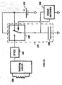
- a TET system and method in accordance with the present invention is shown in Figure 1 for an implantable drug infusion pump in telemetric communication with an external device, e.g., a control unit or PC.
- an external device e.g., a control unit or PC.
- the present invention is suitable for any closed system comprising two electronic devices that communicate via telemetric link, wherein the energy used to power the internal device is optimally switched from an internal power source to an external RF source produced by the external device during communication with the internal device.
- the exemplary TET system shown Figure 1 comprises an external device 100 (e.g., a control unit) in telemetric communication with an implantable medical device 105 (e.g., an implantable drug infusion pump).
- External device 100 includes a primary coil 110 connected to a tuned matching network or circuit 115.
- a demodulator 150 is connected to the matching network 115 and demodulates the data signal from the received carrier signal.
- the demodulator 150 is electrically connected by a microprocessor or controller 140.
- a transmitter 145 is connected between the microprocessor 140 and matching network 115. All components and circuitry associated with the external device 100 are powered by a primary power source 125.
- the power source 125 for powering the external device and its associated circuitry and components is a secondary/rechargeable battery, most preferably a smart rechargeable battery.
- the implantable medical device 105 has an associated secondary coil 120 connected to tuned a matching network or circuit 155.
- a demodulator 160 is connected to the matching network 155 for extracting the data signal from the received carrier signal.
- Microprocessor 135 is, in turn, connected to the demodulator 160.
- Electrically connected between the microprocessor 135 and matching network 155 is a modulator 170 for modulating the signal prior to transmission to the external device 100.
- a secondary or internal power source 130 provides power to all the components and circuitry associated with the implantable medical device.
- the implantable medical device 105 such as an implantable drug infusion pump remains continuously active at all times to maintain operation of the components and circuitry associated therewith.
- the secondary power source 130 is preferably a primary/non-rechargeable battery.
- the components and circuitry of the implantable medical device 105 have been powered exclusively by its associated internal power source 130, e.g., battery.
- an RF field is generated.
- This external RF energy source may be used as an alternative source for providing power needed by the implantable medical device 105 and associated circuitry to operate which would otherwise be drawn from the internal battery 130 associated with the implantable medical device.
- the implantable medical device 105 in accordance with the present invention has been designed to include a high frequency-to-DC converter (HF/DC) 180 and passive power switching circuitry 175 to optimally switch powering of the implantable medical device 105 and its associated components and circuitry from the internal power source 130 to the external RF energy source. Switching between power sources should preferably be instantaneous, automatic and relatively smooth.
- HF/DC high frequency-to-DC converter
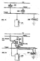
- FIGs 2a & 2b represent schematic and flow diagrams, respectively, of exemplary passive power switching circuitry 175 of Figure 1 using diodes.
- power switching circuitry 175 is used to switch between an internal battery source 130 associated with the implantable medical device 105 and an external RF energy source emitted by an external device 100 during communication with the implantable medical device.
- demodulator 160, microprocessor 135 and modulator 170 are generically represented by implant electronics 200.
- the implantable medical device may include additional components as part of the implant electronics 200 depending on the particular functionality of the implant device.
- an implantable drug infusion pump may include circuitry for controlling the opening and closing of the valve to the reservoir in which the medication is stored.
- a first diode 205 is electrically connected between the voltage supply line (Vsupply) and the RF voltage (Vrf), while a second diode 210 is connected between the voltage supply line (Vsupply) and the battery voltage (Vbattery).
- a capacitor 220 is connected to the voltage supply line (Vsupply) and serves as the stopgap energy supplier during switching of the power supply between Vbattery and Vrf to prevent any interruption in communication.
- the components when powered by the internal battery utilize substantially all the energy in the battery.
- the implantable components may require a minimum of approximately 1.8 V and a maximum of approximately 3.6 V to operate, while the battery voltage is selected to be approximately 2.8 V when fully charged and drops to approximately 1.8 V towards the end of life of the battery.
- a forward voltage drop is experienced across the diode. This drop in voltage will reduce the full range of the battery that is able to power the components.
- a diode such as a Schottky diode having a relatively low voltage drop, preferably approximately 0.2 V to approximately 0.4 V.
- the components Due to the forward voltage drop across the diode the components will operate between approximately 2.8 V and approximately 2.1 V (minimum working voltage of approximately 1.8 V + diode forward voltage drop (e.g., approximately 0.3 V)). Once the battery voltage falls below approximately 2.1 V (minimum working voltage of approximately 1.8 V + the forward voltage drop (e.g., approximately 0.3 V)) the battery will not be able to supply the voltage needed to operate the components. Thus, the full battery range capable of powering the components is reduced by the forward voltage drop across the diode.
- the second diode 210 is reverse biased and all power is drawn from the external RF power source.
- a backward or reverse leakage current is exhibited in diode 210 which is detrimental to the battery 130.
- a leakage current path is created via a switch 217 connected in series to a resistor 215 whose resistance is lower than that of the battery 130. In the presence of an external RF voltage, switch 217 is closed so that the leakage current flows through the resistor 215 rather than the battery 130.
- the first diode 205 is reverse biased and all components in the implantable medical device draw power from the battery 130.
- switching of the power source used to energize the implantable medical device and its associated components from the battery to the external RF energy source emitted by the external device during communication with the implant will occur only when the power supplied by the emitted RF field exceeds that required to energize the implantable medical device and its associated components.
- Substantially all the battery potential is typically consumed by the components and associated circuitry of the implantable medical device when powered by the battery 130. Under such circumstances, switching from the internal power source 130 to the external RF power source will take place only when the external RF voltage potential exceeds the battery voltage.
- the implantable device may employ active power switching circuitry.
- Figures 3a & 3b show a schematic diagram and flow diagram, respectively, of exemplary active power switching circuitry 190 using an analog switch.
- implant electronics block 200 generically represents the modulator 170, demodulator 160, microprocessor 135 and any other circuitry associated with the specific functionality of the implant that is not otherwise specifically shown.
- An analog switch 305 is electrically connected to the RF voltage supply line (Vrf), the battery voltage supply line (Vbattery), and the voltage supply line (Vsupply).
- the analog switch 305 is chosen so as to satisfy the following requirements: relatively low ON resistance; relatively high OFF resistance; relatively low leakage current; relatively low capacitance.
- analog switch 305 is continuously powered by the battery 130. Accordingly, as depicted in the flow diagram of Figure 3b, the battery supply line (Vbattery) is electrically connected to the normally closed (NC) input of the analog switch 305, while the RF voltage supply line (Vrf) is connected to the normally open (NO) input of analog switch 305.
- the battery supply line Vbattery
- the RF voltage supply line Vrf
- NO normally open
- the microprocessor 135 in the implantable medical device determines whether the power supplied by the external RF energy source exceeds that required to energize the implantable medical device and its associated components. If so, microprocessor 135 asserts an enable signal used to trigger analog switch 305 to switch from the internal power source 130 to the external RF energy source. In the absence of RF communication from the external device to the implantable medical device the enable signal from the microprocessor 135 is disabled and the capacitor 220 connected to the Vsupply line is charged automatically from the battery 130. As discussed above, capacitor 220 serves as the stopgap energy supplier while switching from the internal battery to the external RF energy source supplying power to the implantable medical device and its associated components.
Landscapes
- Engineering & Computer Science (AREA)
- Power Engineering (AREA)
- Computer Networks & Wireless Communication (AREA)
- Electrotherapy Devices (AREA)
- Transmitters (AREA)
Priority Applications (1)
| Application Number | Priority Date | Filing Date | Title |
|---|---|---|---|
| PL05256104T PL1643612T3 (pl) | 2004-09-30 | 2005-09-29 | Obwody przełączające podwójnego zasilania energią do użycia w system zamknięty |
Applications Claiming Priority (1)
| Application Number | Priority Date | Filing Date | Title |
|---|---|---|---|
| US10/955,678 US7720546B2 (en) | 2004-09-30 | 2004-09-30 | Dual power supply switching circuitry for use in a closed system |
Publications (3)
| Publication Number | Publication Date |
|---|---|
| EP1643612A2 true EP1643612A2 (de) | 2006-04-05 |
| EP1643612A3 EP1643612A3 (de) | 2006-10-04 |
| EP1643612B1 EP1643612B1 (de) | 2017-03-01 |
Family
ID=35462637
Family Applications (1)
| Application Number | Title | Priority Date | Filing Date |
|---|---|---|---|
| EP05256104.0A Expired - Lifetime EP1643612B1 (de) | 2004-09-30 | 2005-09-29 | Schaltungsanordnung für eine zweifache Stromversorgung zur Verwendung in einem geschlossenen system |
Country Status (5)
| Country | Link |
|---|---|
| US (2) | US7720546B2 (de) |
| EP (1) | EP1643612B1 (de) |
| AU (1) | AU2005209677B2 (de) |
| CA (1) | CA2521408C (de) |
| PL (1) | PL1643612T3 (de) |
Cited By (2)
| Publication number | Priority date | Publication date | Assignee | Title |
|---|---|---|---|---|
| WO2012036380A2 (en) | 2010-09-15 | 2012-03-22 | Samsung Electronics Co., Ltd. | Apparatus for wireless power transmission and reception |
| EP2072080A3 (de) * | 2005-12-07 | 2014-04-09 | Boston Scientific Neuromodulation Corporation | Batterieschutz- und Null-Volt-Batterie-Wiederaufladungssystem für eine implantierbare medizinische Vorrichtung |
Families Citing this family (42)
| Publication number | Priority date | Publication date | Assignee | Title |
|---|---|---|---|---|
| US7076307B2 (en) * | 2002-05-09 | 2006-07-11 | Boveja Birinder R | Method and system for modulating the vagus nerve (10th cranial nerve) with electrical pulses using implanted and external components, to provide therapy neurological and neuropsychiatric disorders |
| US7437644B2 (en) * | 2004-10-29 | 2008-10-14 | Codman Neuro Sciences Sárl | Automatic self-testing of an internal device in a closed system |
| KR100667157B1 (ko) * | 2004-12-13 | 2007-01-12 | 한국전자통신연구원 | 텔레매틱스 단말기의 전원 공급 장치 |
| US20070142696A1 (en) | 2005-12-08 | 2007-06-21 | Ventrassist Pty Ltd | Implantable medical devices |
| US7904734B1 (en) * | 2007-09-04 | 2011-03-08 | Juniper Networks, Inc. | Increasing mean time between failures for power supplies |
| FI20095973A0 (fi) | 2009-09-22 | 2009-09-22 | Powerkiss Oy | Induktiivinen tehonsyöttö |
| EP2315465A1 (de) * | 2009-10-20 | 2011-04-27 | ETH Zurich | Verfahren zur sicheren Kommunikation zwischen Geräten |
| US8344789B2 (en) * | 2010-01-20 | 2013-01-01 | Intersil Americas Inc. | Analog switch with internal device body control |
| US8594806B2 (en) | 2010-04-30 | 2013-11-26 | Cyberonics, Inc. | Recharging and communication lead for an implantable device |
| US8386051B2 (en) | 2010-12-30 | 2013-02-26 | Medtronic, Inc. | Disabling an implantable medical device |
| US8615303B2 (en) * | 2011-02-17 | 2013-12-24 | Cochlear Limited | Power transfer to a medical implant located adjacent to tissue while preventing short circuits through the tissue |
| US20120232615A1 (en) * | 2011-03-07 | 2012-09-13 | Giancarlo Barolat | Modular Limb Peripheral Nerve Stimulation System and Method of Use |
| US9446254B2 (en) * | 2011-10-13 | 2016-09-20 | Boston Scientific Neuromodulation Corporation | Charger alignment in an implantable medical device system employing reflected impedance modulation |
| WO2014018967A1 (en) | 2012-07-27 | 2014-01-30 | Thoratec Corporation | Self-tuning resonant power transfer systems |
| US9592397B2 (en) | 2012-07-27 | 2017-03-14 | Thoratec Corporation | Thermal management for implantable wireless power transfer systems |
| US9805863B2 (en) | 2012-07-27 | 2017-10-31 | Thoratec Corporation | Magnetic power transmission utilizing phased transmitter coil arrays and phased receiver coil arrays |
| US10383990B2 (en) | 2012-07-27 | 2019-08-20 | Tc1 Llc | Variable capacitor for resonant power transfer systems |
| US10291067B2 (en) | 2012-07-27 | 2019-05-14 | Tc1 Llc | Computer modeling for resonant power transfer systems |
| WO2014018971A1 (en) | 2012-07-27 | 2014-01-30 | Thoratec Corporation | Resonant power transfer systems with protective algorithm |
| WO2014018973A1 (en) | 2012-07-27 | 2014-01-30 | Thoratec Corporation | Resonant power transmission coils and systems |
| US10525181B2 (en) | 2012-07-27 | 2020-01-07 | Tc1 Llc | Resonant power transfer system and method of estimating system state |
| US9343923B2 (en) | 2012-08-23 | 2016-05-17 | Cyberonics, Inc. | Implantable medical device with backscatter signal based communication |
| US9935498B2 (en) | 2012-09-25 | 2018-04-03 | Cyberonics, Inc. | Communication efficiency with an implantable medical device using a circulator and a backscatter signal |
| US9755456B1 (en) * | 2013-02-01 | 2017-09-05 | Electrochem Solutions, Inc. | Control circuit for wireless power |
| US10373756B2 (en) | 2013-03-15 | 2019-08-06 | Tc1 Llc | Malleable TETs coil with improved anatomical fit |
| WO2014145664A1 (en) | 2013-03-15 | 2014-09-18 | Thoratec Corporation | Integrated implantable tets housing including fins and coil loops |
| WO2015070200A1 (en) | 2013-11-11 | 2015-05-14 | Thoratec Corporation | Resonant power transfer systems with communications |
| EP3069358B1 (de) | 2013-11-11 | 2019-06-12 | Tc1 Llc | Resonante stromübertragungsspule mit einem scharnier |
| EP3072210B1 (de) | 2013-11-11 | 2023-12-20 | Tc1 Llc | Resonante stromübertragungssysteme mit kommunikation |
| US9345883B2 (en) | 2014-02-14 | 2016-05-24 | Boston Scientific Neuromodulation Corporation | Rechargeable-battery implantable medical device having a primary battery active during a rechargeable-battery undervoltage condition |
| WO2015134871A1 (en) | 2014-03-06 | 2015-09-11 | Thoratec Corporation | Electrical connectors for implantable devices |
| EP3826104B1 (de) | 2014-09-22 | 2023-05-03 | Tc1 Llc | Antennenentwürfe zur kommunikation zwischen einem drahtlos betriebenen implantat mit einer externen vorrichtung ausserhalb des körpers |
| EP3204989B1 (de) | 2014-10-06 | 2019-08-21 | Tc1 Llc | Mehrachsiger steckverbinder für implantierbare vorrichtungen |
| US9867994B2 (en) | 2015-06-19 | 2018-01-16 | Boston Scientific Neuromodulation Corporation | External powering of implantable medical device dependent on energy of provided therapy |
| US10148126B2 (en) | 2015-08-31 | 2018-12-04 | Tc1 Llc | Wireless energy transfer system and wearables |
| EP3148050B1 (de) | 2015-09-25 | 2019-06-05 | Greatbatch Ltd. | Schutz von drahtloskommunikationskomponenten in einem hochresonanten feld |
| EP3902100A1 (de) | 2015-10-07 | 2021-10-27 | Tc1 Llc | Resonante leistungsübertragungssysteme mit effizienzoptimierung basierend auf empfängerimpedanz |
| US10425751B2 (en) | 2015-12-18 | 2019-09-24 | Cochlear Limited | Dual power supply |
| US10898292B2 (en) | 2016-09-21 | 2021-01-26 | Tc1 Llc | Systems and methods for locating implanted wireless power transmission devices |
| WO2018136592A2 (en) | 2017-01-18 | 2018-07-26 | Tc1 Llc | Systems and methods for transcutaneous power transfer using microneedles |
| WO2019135890A1 (en) | 2018-01-04 | 2019-07-11 | Tc1 Llc | Systems and methods for elastic wireless power transmission devices |
| WO2025088448A1 (en) * | 2023-10-27 | 2025-05-01 | Medtronic, Inc. | Augmented power system for implantable medical device |
Family Cites Families (119)
| Publication number | Priority date | Publication date | Assignee | Title |
|---|---|---|---|---|
| JPS36022343B1 (de) | 1959-12-24 | 1961-11-18 | Univ Tokyo | |
| US3209081A (en) | 1961-10-02 | 1965-09-28 | Behrman A Ducote | Subcutaneously implanted electronic device |
| US3357434A (en) | 1964-04-06 | 1967-12-12 | Avco Corp | Inductively linked receiver |
| US3662758A (en) | 1969-06-30 | 1972-05-16 | Mentor Corp | Stimulator apparatus for muscular organs with external transmitter and implantable receiver |
| US3888260A (en) | 1972-06-28 | 1975-06-10 | Univ Johns Hopkins | Rechargeable demand inhibited cardiac pacer and tissue stimulator |
| US3942535A (en) | 1973-09-27 | 1976-03-09 | G. D. Searle & Co. | Rechargeable tissue stimulating system |
| GB1505130A (en) | 1974-05-07 | 1978-03-22 | Seiko Instr & Electronics | Systems for detecting information in an artificial cardiac pacemaker |
| US4071032A (en) | 1976-01-29 | 1978-01-31 | Pacesetter Systems Inc. | Implantable living tissue stimulators |
| US4082097A (en) * | 1976-05-20 | 1978-04-04 | Pacesetter Systems Inc. | Multimode recharging system for living tissue stimulators |
| US4134408A (en) | 1976-11-12 | 1979-01-16 | Research Corporation | Cardiac pacer energy conservation system |
| US4102344A (en) | 1976-11-15 | 1978-07-25 | Mentor Corporation | Stimulator apparatus for internal body organ |
| US4186749A (en) | 1977-05-12 | 1980-02-05 | The United States Of America As Represented By The Administrator Of The National Aeronautics And Space Administration | Induction powered biological radiosonde |
| US4187854A (en) | 1977-10-17 | 1980-02-12 | Medtronic, Inc. | Implantable demand pacemaker and monitor |
| US4166470A (en) | 1977-10-17 | 1979-09-04 | Medtronic, Inc. | Externally controlled and powered cardiac stimulating apparatus |
| US4172459A (en) | 1977-10-17 | 1979-10-30 | Medtronic, Inc. | Cardiac monitoring apparatus and monitor |
| US4373527B1 (en) | 1979-04-27 | 1995-06-27 | Univ Johns Hopkins | Implantable programmable medication infusion system |
| US4793353A (en) | 1981-06-30 | 1988-12-27 | Borkan William N | Non-invasive multiprogrammable tissue stimulator and method |
| US4561443A (en) | 1983-03-08 | 1985-12-31 | The Johns Hopkins University | Coherent inductive communications link for biomedical applications |
| US4543953A (en) | 1983-07-18 | 1985-10-01 | Cordis Corporation | Analog telemetry system for biomedical implant |
| US4528987A (en) | 1983-09-28 | 1985-07-16 | Cordis Corporation | Apparatus and process for communicating an electrogram |
| US4941201A (en) | 1985-01-13 | 1990-07-10 | Abbott Laboratories | Electronic data storage and retrieval apparatus and method |
| US4980898A (en) | 1989-08-08 | 1990-12-25 | Siemens-Pacesetter, Inc. | Self-oscillating burst mode transmitter with integral number of periods |
| US5938691A (en) | 1989-09-22 | 1999-08-17 | Alfred E. Mann Foundation | Multichannel implantable cochlear stimulator |
| US5876425A (en) | 1989-09-22 | 1999-03-02 | Advanced Bionics Corporation | Power control loop for implantable tissue stimulator |
| GB9011970D0 (en) | 1990-05-29 | 1990-07-18 | Leigh Stewart Prod | Electrical control system for,for example,an air spa bath |
| US5314458A (en) | 1990-06-01 | 1994-05-24 | University Of Michigan | Single channel microstimulator |
| US5113869A (en) | 1990-08-21 | 1992-05-19 | Telectronics Pacing Systems, Inc. | Implantable ambulatory electrocardiogram monitor |
| US5117825A (en) | 1990-11-09 | 1992-06-02 | John Grevious | Closed loop transmitter for medical implant |
| DE4104359A1 (de) | 1991-02-13 | 1992-08-20 | Implex Gmbh | Ladesystem fuer implantierbare hoerhilfen und tinnitus-maskierer |
| US5314453A (en) | 1991-12-06 | 1994-05-24 | Spinal Cord Society | Position sensitive power transfer antenna |
| US5358514A (en) | 1991-12-18 | 1994-10-25 | Alfred E. Mann Foundation For Scientific Research | Implantable microdevice with self-attaching electrodes |
| US5229652A (en) | 1992-04-20 | 1993-07-20 | Hough Wayne E | Non-contact data and power connector for computer based modules |
| US5342408A (en) | 1993-01-07 | 1994-08-30 | Incontrol, Inc. | Telemetry system for an implantable cardiac device |
| US5314457A (en) | 1993-04-08 | 1994-05-24 | Jeutter Dean C | Regenerative electrical |
| US5383912A (en) | 1993-05-05 | 1995-01-24 | Intermedics, Inc. | Apparatus for high speed data communication between an external medical device and an implantable medical device |
| US5455466A (en) | 1993-07-29 | 1995-10-03 | Dell Usa, L.P. | Inductive coupling system for power and data transfer |
| US5411537A (en) | 1993-10-29 | 1995-05-02 | Intermedics, Inc. | Rechargeable biomedical battery powered devices with recharging and control system therefor |
| US5476488A (en) | 1993-12-15 | 1995-12-19 | Pacesetter, Inc. | Telemetry system power control for implantable medical devices |
| US5626630A (en) | 1994-10-13 | 1997-05-06 | Ael Industries, Inc. | Medical telemetry system using an implanted passive transponder |
| US5613935A (en) | 1994-12-16 | 1997-03-25 | Jarvik; Robert | High reliability cardiac assist system |
| US5591217A (en) | 1995-01-04 | 1997-01-07 | Plexus, Inc. | Implantable stimulator with replenishable, high value capacitive power source and method therefor |
| US5690693A (en) | 1995-06-07 | 1997-11-25 | Sulzer Intermedics Inc. | Transcutaneous energy transmission circuit for implantable medical device |
| CA2235216C (en) | 1995-10-19 | 2006-05-30 | The University Of Melbourne | Embedded data link and protocol |
| US5733313A (en) | 1996-08-01 | 1998-03-31 | Exonix Corporation | RF coupled, implantable medical device with rechargeable back-up power source |
| US5713939A (en) | 1996-09-16 | 1998-02-03 | Sulzer Intermedics Inc. | Data communication system for control of transcutaneous energy transmission to an implantable medical device |
| US5735887A (en) | 1996-12-10 | 1998-04-07 | Exonix Corporation | Closed-loop, RF-coupled implanted medical device |
| US5894413A (en) | 1997-01-28 | 1999-04-13 | Sony Corporation | Redundant power supply switchover circuit |
| EP1666087A3 (de) | 1997-02-26 | 2009-04-29 | The Alfred E Mann Foundation for Scientific Research | Batterie-Betriebsgerät zur Implantation in einem Patienten |
| US5991664A (en) | 1997-03-09 | 1999-11-23 | Cochlear Limited | Compact inductive arrangement for medical implant data and power transfer |
| US6699187B2 (en) | 1997-03-27 | 2004-03-02 | Medtronic, Inc. | System and method for providing remote expert communications and video capabilities for use during a medical procedure |
| ATE277672T1 (de) | 1997-08-01 | 2004-10-15 | Mann Alfred E Found Scient Res | Implantierbare einrichtung mit verbesserter anordnung zur ladung der batterie und zur energiezufuhr |
| US6239724B1 (en) | 1997-12-30 | 2001-05-29 | Remon Medical Technologies, Ltd. | System and method for telemetrically providing intrabody spatial position |
| FI104462B (fi) | 1998-03-02 | 2000-02-15 | Polar Electro Oy | Latausmenetelmä ja -järjestely |
| US6058330A (en) | 1998-03-06 | 2000-05-02 | Dew Engineering And Development Limited | Transcutaneous energy transfer device |
| US6047214A (en) | 1998-06-09 | 2000-04-04 | North Carolina State University | System and method for powering, controlling, and communicating with multiple inductively-powered devices |
| US6324430B1 (en) | 1998-07-06 | 2001-11-27 | Abiomed, Inc. | Magnetic shield for primary coil of transcutaneous energy transfer device |
| US6324431B1 (en) | 1998-07-06 | 2001-11-27 | Abiomed, Inc. | Transcutaneous energy transfer device with magnetic field protected components in secondary coil |
| GB9816011D0 (en) | 1998-07-22 | 1998-09-23 | Habib Nagy A | Monitoring treatment using implantable telemetric sensors |
| US6308101B1 (en) | 1998-07-31 | 2001-10-23 | Advanced Bionics Corporation | Fully implantable cochlear implant system |
| US6554798B1 (en) | 1998-08-18 | 2003-04-29 | Medtronic Minimed, Inc. | External infusion device with remote programming, bolus estimator and/or vibration alarm capabilities |
| DE19837913C2 (de) | 1998-08-20 | 2000-09-28 | Implex Hear Tech Ag | Implantierbare Vorrichtung mit einer eine Empfangsspule aufweisenden Ladestromeinspeiseanordnung |
| US6275737B1 (en) | 1998-10-14 | 2001-08-14 | Advanced Bionics Corporation | Transcutaneous transmission pouch |
| US6073050A (en) | 1998-11-10 | 2000-06-06 | Advanced Bionics Corporation | Efficient integrated RF telemetry transmitter for use with implantable device |
| EP1048324A3 (de) | 1999-04-30 | 2002-10-16 | Medtronic, Inc. | Durch wiederaufladbare Li+ Batterien betriebener implantierbarer medizinischer Stimulator |
| US6212430B1 (en) | 1999-05-03 | 2001-04-03 | Abiomed, Inc. | Electromagnetic field source with detection of position of secondary coil in relation to multiple primary coils |
| US6127799A (en) | 1999-05-14 | 2000-10-03 | Gte Internetworking Incorporated | Method and apparatus for wireless powering and recharging |
| US6516227B1 (en) | 1999-07-27 | 2003-02-04 | Advanced Bionics Corporation | Rechargeable spinal cord stimulator system |
| US6553263B1 (en) | 1999-07-30 | 2003-04-22 | Advanced Bionics Corporation | Implantable pulse generators using rechargeable zero-volt technology lithium-ion batteries |
| US6445956B1 (en) | 1999-10-18 | 2002-09-03 | Abiomed, Inc. | Implantable medical device |
| US6644321B1 (en) | 1999-10-29 | 2003-11-11 | Medtronic, Inc. | Tactile feedback for indicating validity of communication link with an implantable medical device |
| US6400956B1 (en) * | 1999-11-15 | 2002-06-04 | Lucent Technologies Inc. | Method and apparatus for a wireless telecommunication system that provides location-based action services |
| US6278624B1 (en) | 1999-12-01 | 2001-08-21 | Hewlett-Packard Company | High availability DC power supply with isolated inputs, diode-or-connected outputs, and power factor correction |
| US6415186B1 (en) | 2000-01-14 | 2002-07-02 | Advanced Bionics Corporation | Active feed forward power control loop |
| US6562001B2 (en) | 2000-01-21 | 2003-05-13 | Medtronic Minimed, Inc. | Microprocessor controlled ambulatory medical apparatus with hand held communication device |
| US6920359B2 (en) | 2000-02-15 | 2005-07-19 | Advanced Bionics Corporation | Deep brain stimulation system for the treatment of Parkinson's Disease or other disorders |
| US6631296B1 (en) | 2000-03-17 | 2003-10-07 | Advanced Bionics Corporation | Voltage converter for implantable microstimulator using RF-powering coil |
| US6458164B1 (en) | 2000-04-25 | 2002-10-01 | The Penn State Research Foundation | Artificial heart with energy recovery |
| US6456883B1 (en) * | 2000-04-26 | 2002-09-24 | Medtronic, Inc. | Apparatus and method for allowing immediate retrieval for information and identification from an implantable medical device having a depleted power source |
| US7167756B1 (en) | 2000-04-28 | 2007-01-23 | Medtronic, Inc. | Battery recharge management for an implantable medical device |
| US6850803B1 (en) | 2000-06-16 | 2005-02-01 | Medtronic, Inc. | Implantable medical device with a recharging coil magnetic shield |
| US6738670B1 (en) | 2000-06-19 | 2004-05-18 | Medtronic, Inc. | Implantable medical device telemetry processor |
| US6505077B1 (en) | 2000-06-19 | 2003-01-07 | Medtronic, Inc. | Implantable medical device with external recharging coil electrical connection |
| CN1200641C (zh) | 2000-11-20 | 2005-05-11 | 美国西门子医疗解决公司 | 一种使用电隔离的组合功率和信号耦合器系统的便携病人监视器装置以及对接座 |
| US7126310B1 (en) | 2001-04-20 | 2006-10-24 | Abiomed, Inc. | Apparatus and method for balanced charging of a multiple-cell battery pack |
| US6675049B2 (en) | 2001-07-17 | 2004-01-06 | Medtronic, Inc. | Method and apparatus for automatic implantable medical lead recognition and configuration |
| WO2003033070A1 (en) | 2001-10-16 | 2003-04-24 | Case Western Reserve University | Neural prosthesis |
| US6894456B2 (en) | 2001-11-07 | 2005-05-17 | Quallion Llc | Implantable medical power module |
| US6985773B2 (en) | 2002-02-07 | 2006-01-10 | Cardiac Pacemakers, Inc. | Methods and apparatuses for implantable medical device telemetry power management |
| US7818180B2 (en) | 2002-04-29 | 2010-10-19 | Medtronic, Inc. | Personalization software for implanted medical device patients |
| US7831152B2 (en) | 2002-06-04 | 2010-11-09 | Finisar Corporation | Optical transceiver |
| US7437193B2 (en) | 2002-06-28 | 2008-10-14 | Boston Scientific Neuromodulation Corporation | Microstimulator employing improved recharging reporting and telemetry techniques |
| US6870475B2 (en) | 2002-07-08 | 2005-03-22 | Draeger Medical Systems Inc. | Electrically isolated power and data coupling system suitable for portable and other equipment |
| EP1562674A4 (de) | 2002-10-15 | 2008-10-08 | Medtronic Inc | Kontrolle der behandlung bei beginn und im betrieb einesmedizinischen vorrichtungssystems |
| US7613497B2 (en) | 2003-07-29 | 2009-11-03 | Biosense Webster, Inc. | Energy transfer amplification for intrabody devices |
| US7571008B2 (en) | 2003-08-18 | 2009-08-04 | Medtronic, Inc. | System and apparatus for remote activation of implantable medical devices |
| US20050075696A1 (en) | 2003-10-02 | 2005-04-07 | Medtronic, Inc. | Inductively rechargeable external energy source, charger, system and method for a transcutaneous inductive charger for an implantable medical device |
| US7356369B2 (en) | 2003-10-02 | 2008-04-08 | Medtronic, Inc. | Z-axis assembly of medical device programmer |
| US8140168B2 (en) | 2003-10-02 | 2012-03-20 | Medtronic, Inc. | External power source for an implantable medical device having an adjustable carrier frequency and system and method related therefore |
| US7308316B2 (en) | 2003-10-02 | 2007-12-11 | Medtronic, Inc. | Storable implantable medical device assembly allowing in package charging |
| US7561921B2 (en) | 2003-10-02 | 2009-07-14 | Medtronic, Inc. | Neurostimulator programmer with internal antenna |
| EP1673143B1 (de) | 2003-10-02 | 2012-08-22 | Medtronic, Inc. | Benutzeroberfläche für externes ladegerät eines implantierbaren medizinischen gerätes |
| US7729766B2 (en) | 2003-10-02 | 2010-06-01 | Medtronic, Inc. | Circuit board construction for handheld programmer |
| US20050182459A1 (en) | 2003-12-30 | 2005-08-18 | John Constance M. | Apparatus for harvesting and storing energy on a chip |
| US7288918B2 (en) | 2004-03-02 | 2007-10-30 | Distefano Michael Vincent | Wireless battery charger via carrier frequency signal |
| US7212110B1 (en) * | 2004-04-19 | 2007-05-01 | Advanced Neuromodulation Systems, Inc. | Implantable device and system and method for wireless communication |
| US7761167B2 (en) | 2004-06-10 | 2010-07-20 | Medtronic Urinary Solutions, Inc. | Systems and methods for clinician control of stimulation systems |
| US7565197B2 (en) | 2004-06-18 | 2009-07-21 | Medtronic, Inc. | Conditional requirements for remote medical device programming |
| WO2006014687A1 (en) | 2004-07-20 | 2006-02-09 | Medtronic, Inc. | Switched power using telemetry in an implantable medical device |
| US7528094B2 (en) | 2004-10-25 | 2009-05-05 | Medtronic, Inc. | Method and apparatus for providing safe long-range telemetry with implantable medical devices |
| US7682745B2 (en) | 2004-10-29 | 2010-03-23 | Medtronic, Inc. | Medical device having lithium-ion battery |
| US7582387B2 (en) | 2004-10-29 | 2009-09-01 | Medtronic, Inc. | Lithium-ion battery |
| KR101326118B1 (ko) | 2004-10-29 | 2013-11-06 | 메드트로닉 인코포레이티드 | 리튬 이온 전지의 충전방법 |
| US7641992B2 (en) | 2004-10-29 | 2010-01-05 | Medtronic, Inc. | Medical device having lithium-ion battery |
| US7668600B2 (en) | 2006-01-19 | 2010-02-23 | Medtronic, Inc. | System and method for telemetry with an implantable medical device |
| US7574266B2 (en) | 2006-01-19 | 2009-08-11 | Medtronic, Inc. | System and method for telemetry with an implantable medical device |
| US7840276B2 (en) | 2006-04-26 | 2010-11-23 | Medtronic, Inc. | Generic device programmer network interface |
| US7738951B2 (en) | 2006-07-28 | 2010-06-15 | Medtronic, Inc. | Prioritized multicomplexor sensing circuit |
| WO2008069896A2 (en) | 2006-12-06 | 2008-06-12 | Medtronic, Inc. | Telemetry device for a medical device programmer |
| US7391257B1 (en) | 2007-01-31 | 2008-06-24 | Medtronic, Inc. | Chopper-stabilized instrumentation amplifier for impedance measurement |
-
2004
- 2004-09-30 US US10/955,678 patent/US7720546B2/en not_active Expired - Fee Related
-
2005
- 2005-09-12 AU AU2005209677A patent/AU2005209677B2/en not_active Ceased
- 2005-09-28 CA CA2521408A patent/CA2521408C/en not_active Expired - Fee Related
- 2005-09-29 EP EP05256104.0A patent/EP1643612B1/de not_active Expired - Lifetime
- 2005-09-29 PL PL05256104T patent/PL1643612T3/pl unknown
-
2009
- 2009-03-11 US US12/381,436 patent/US8929996B2/en not_active Expired - Fee Related
Cited By (3)
| Publication number | Priority date | Publication date | Assignee | Title |
|---|---|---|---|---|
| EP2072080A3 (de) * | 2005-12-07 | 2014-04-09 | Boston Scientific Neuromodulation Corporation | Batterieschutz- und Null-Volt-Batterie-Wiederaufladungssystem für eine implantierbare medizinische Vorrichtung |
| WO2012036380A2 (en) | 2010-09-15 | 2012-03-22 | Samsung Electronics Co., Ltd. | Apparatus for wireless power transmission and reception |
| EP2617119A4 (de) * | 2010-09-15 | 2016-04-27 | Samsung Electronics Co Ltd | Gerät für drahtloses senden und empfangen von energie |
Also Published As
| Publication number | Publication date |
|---|---|
| CA2521408C (en) | 2014-12-30 |
| US20060069412A1 (en) | 2006-03-30 |
| EP1643612A3 (de) | 2006-10-04 |
| PL1643612T3 (pl) | 2017-07-31 |
| EP1643612B1 (de) | 2017-03-01 |
| CA2521408A1 (en) | 2006-03-30 |
| US20090228077A1 (en) | 2009-09-10 |
| AU2005209677A1 (en) | 2006-04-13 |
| AU2005209677B2 (en) | 2011-07-28 |
| US7720546B2 (en) | 2010-05-18 |
| US8929996B2 (en) | 2015-01-06 |
Similar Documents
| Publication | Publication Date | Title |
|---|---|---|
| US7720546B2 (en) | Dual power supply switching circuitry for use in a closed system | |
| US20250381019A1 (en) | Method of placing a control assembly | |
| US7428438B2 (en) | Systems and methods for providing power to a battery in an implantable stimulator | |
| US8764621B2 (en) | Transcutaneous power transmission and communication for implanted heart assist and other devices | |
| CN101803965B (zh) | 控制小便失禁的治疗 | |
| AU691778B2 (en) | Implantable stimulator with replenishable high value capacitive power source and method therefor | |
| US8175717B2 (en) | Ultracapacitor powered implantable pulse generator with dedicated power supply | |
| EP1609501B1 (de) | Medizinisches Implantat mit einer Schaltung zur transkutanen Energieübertragung mit geschlossenem Kreislauf zur Übertragungsleistungssteuerung | |
| EP2812071B1 (de) | Stromarchitektur für eine implantierbare medizinische vorrichtung mit nicht aufladbarer batterie | |
| US20170196670A1 (en) | Anal incontinence disease treatment with controlled wireless energy supply | |
| US10813744B2 (en) | Rechargeable intraocular implant | |
| EP2643053B1 (de) | Automatische energieregelung für ein transkutanes energieübertragungs-ladesystem | |
| JP2009518144A (ja) | 移植可能な医療装置用のバッテリ保護及びゼロボルトバッテリ復帰システム | |
| WO2007120946A2 (en) | Cross-band communications in an implantable device | |
| CA2548284C (en) | Telemetry system and method with variable parameters | |
| US20240172956A1 (en) | Voice control system for an implant | |
| US20210378811A1 (en) | Fastening means for implantable medical control assembly | |
| AU2014307084B2 (en) | Power architecture for an implantable medical device having a non-rechargeable battery | |
| WO1998008567A1 (en) | Electronically operated medical implant and a storage system for such an implant | |
| Mounaim et al. | Implantable neuro-monito-stimulation system dedicated to enhance the bladder functions |
Legal Events
| Date | Code | Title | Description |
|---|---|---|---|
| PUAI | Public reference made under article 153(3) epc to a published international application that has entered the european phase |
Free format text: ORIGINAL CODE: 0009012 |
|
| AK | Designated contracting states |
Kind code of ref document: A2 Designated state(s): AT BE BG CH CY CZ DE DK EE ES FI FR GB GR HU IE IS IT LI LT LU LV MC NL PL PT RO SE SI SK TR |
|
| AX | Request for extension of the european patent |
Extension state: AL BA HR MK YU |
|
| PUAL | Search report despatched |
Free format text: ORIGINAL CODE: 0009013 |
|
| AK | Designated contracting states |
Kind code of ref document: A3 Designated state(s): AT BE BG CH CY CZ DE DK EE ES FI FR GB GR HU IE IS IT LI LT LU LV MC NL PL PT RO SE SI SK TR |
|
| AX | Request for extension of the european patent |
Extension state: AL BA HR MK YU |
|
| RIC1 | Information provided on ipc code assigned before grant |
Ipc: H02J 17/00 20060101ALI20060831BHEP Ipc: A61N 1/378 20060101AFI20060831BHEP Ipc: H02J 1/00 20060101ALI20060831BHEP |
|
| 17P | Request for examination filed |
Effective date: 20070315 |
|
| 17Q | First examination report despatched |
Effective date: 20070413 |
|
| AKX | Designation fees paid |
Designated state(s): AT BE BG CH CY CZ DE DK EE ES FI FR GB GR HU IE IS IT LI LT LU LV MC NL PL PT RO SE SI SK TR |
|
| R17C | First examination report despatched (corrected) |
Effective date: 20071116 |
|
| REG | Reference to a national code |
Ref country code: DE Ref legal event code: R079 Ref document number: 602005051397 Country of ref document: DE Free format text: PREVIOUS MAIN CLASS: H02J0017000000 Ipc: H02J0007020000 |
|
| RIC1 | Information provided on ipc code assigned before grant |
Ipc: A61N 1/378 20060101ALI20160715BHEP Ipc: H02J 50/20 20160101ALI20160715BHEP Ipc: H02J 7/02 20060101AFI20160715BHEP Ipc: H02J 1/10 20060101ALI20160715BHEP |
|
| GRAP | Despatch of communication of intention to grant a patent |
Free format text: ORIGINAL CODE: EPIDOSNIGR1 |
|
| INTG | Intention to grant announced |
Effective date: 20160829 |
|
| GRAJ | Information related to disapproval of communication of intention to grant by the applicant or resumption of examination proceedings by the epo deleted |
Free format text: ORIGINAL CODE: EPIDOSDIGR1 |
|
| GRAR | Information related to intention to grant a patent recorded |
Free format text: ORIGINAL CODE: EPIDOSNIGR71 |
|
| GRAS | Grant fee paid |
Free format text: ORIGINAL CODE: EPIDOSNIGR3 |
|
| GRAJ | Information related to disapproval of communication of intention to grant by the applicant or resumption of examination proceedings by the epo deleted |
Free format text: ORIGINAL CODE: EPIDOSDIGR1 |
|
| GRAA | (expected) grant |
Free format text: ORIGINAL CODE: 0009210 |
|
| GRAP | Despatch of communication of intention to grant a patent |
Free format text: ORIGINAL CODE: EPIDOSNIGR1 |
|
| GRAS | Grant fee paid |
Free format text: ORIGINAL CODE: EPIDOSNIGR3 |
|
| INTC | Intention to grant announced (deleted) | ||
| AK | Designated contracting states |
Kind code of ref document: B1 Designated state(s): AT BE BG CH CY CZ DE DK EE ES FI FR GB GR HU IE IS IT LI LT LU LV MC NL PL PT RO SE SI SK TR |
|
| INTG | Intention to grant announced |
Effective date: 20170124 |
|
| REG | Reference to a national code |
Ref country code: GB Ref legal event code: FG4D |
|
| REG | Reference to a national code |
Ref country code: CH Ref legal event code: EP Ref country code: CH Ref legal event code: NV Representative=s name: E. BLUM AND CO. AG PATENT- UND MARKENANWAELTE , CH Ref country code: AT Ref legal event code: REF Ref document number: 872374 Country of ref document: AT Kind code of ref document: T Effective date: 20170315 |
|
| REG | Reference to a national code |
Ref country code: IE Ref legal event code: FG4D |
|
| REG | Reference to a national code |
Ref country code: DE Ref legal event code: R096 Ref document number: 602005051397 Country of ref document: DE |
|
| REG | Reference to a national code |
Ref country code: NL Ref legal event code: MP Effective date: 20170301 |
|
| REG | Reference to a national code |
Ref country code: LT Ref legal event code: MG4D |
|
| PG25 | Lapsed in a contracting state [announced via postgrant information from national office to epo] |
Ref country code: FI Free format text: LAPSE BECAUSE OF FAILURE TO SUBMIT A TRANSLATION OF THE DESCRIPTION OR TO PAY THE FEE WITHIN THE PRESCRIBED TIME-LIMIT Effective date: 20170301 Ref country code: LT Free format text: LAPSE BECAUSE OF FAILURE TO SUBMIT A TRANSLATION OF THE DESCRIPTION OR TO PAY THE FEE WITHIN THE PRESCRIBED TIME-LIMIT Effective date: 20170301 |
|
| REG | Reference to a national code |
Ref country code: FR Ref legal event code: PLFP Year of fee payment: 13 |
|
| PG25 | Lapsed in a contracting state [announced via postgrant information from national office to epo] |
Ref country code: LV Free format text: LAPSE BECAUSE OF FAILURE TO SUBMIT A TRANSLATION OF THE DESCRIPTION OR TO PAY THE FEE WITHIN THE PRESCRIBED TIME-LIMIT Effective date: 20170301 Ref country code: ES Free format text: LAPSE BECAUSE OF FAILURE TO SUBMIT A TRANSLATION OF THE DESCRIPTION OR TO PAY THE FEE WITHIN THE PRESCRIBED TIME-LIMIT Effective date: 20170301 Ref country code: SE Free format text: LAPSE BECAUSE OF FAILURE TO SUBMIT A TRANSLATION OF THE DESCRIPTION OR TO PAY THE FEE WITHIN THE PRESCRIBED TIME-LIMIT Effective date: 20170301 |
|
| PG25 | Lapsed in a contracting state [announced via postgrant information from national office to epo] |
Ref country code: NL Free format text: LAPSE BECAUSE OF FAILURE TO SUBMIT A TRANSLATION OF THE DESCRIPTION OR TO PAY THE FEE WITHIN THE PRESCRIBED TIME-LIMIT Effective date: 20170301 |
|
| PG25 | Lapsed in a contracting state [announced via postgrant information from national office to epo] |
Ref country code: RO Free format text: LAPSE BECAUSE OF FAILURE TO SUBMIT A TRANSLATION OF THE DESCRIPTION OR TO PAY THE FEE WITHIN THE PRESCRIBED TIME-LIMIT Effective date: 20170301 Ref country code: EE Free format text: LAPSE BECAUSE OF FAILURE TO SUBMIT A TRANSLATION OF THE DESCRIPTION OR TO PAY THE FEE WITHIN THE PRESCRIBED TIME-LIMIT Effective date: 20170301 Ref country code: SK Free format text: LAPSE BECAUSE OF FAILURE TO SUBMIT A TRANSLATION OF THE DESCRIPTION OR TO PAY THE FEE WITHIN THE PRESCRIBED TIME-LIMIT Effective date: 20170301 |
|
| REG | Reference to a national code |
Ref country code: GR Ref legal event code: EP Ref document number: 20170401428 Country of ref document: GR Effective date: 20171023 |
|
| PG25 | Lapsed in a contracting state [announced via postgrant information from national office to epo] |
Ref country code: PT Free format text: LAPSE BECAUSE OF FAILURE TO SUBMIT A TRANSLATION OF THE DESCRIPTION OR TO PAY THE FEE WITHIN THE PRESCRIBED TIME-LIMIT Effective date: 20170703 Ref country code: IS Free format text: LAPSE BECAUSE OF FAILURE TO SUBMIT A TRANSLATION OF THE DESCRIPTION OR TO PAY THE FEE WITHIN THE PRESCRIBED TIME-LIMIT Effective date: 20170701 |
|
| REG | Reference to a national code |
Ref country code: DE Ref legal event code: R097 Ref document number: 602005051397 Country of ref document: DE |
|
| PLBE | No opposition filed within time limit |
Free format text: ORIGINAL CODE: 0009261 |
|
| STAA | Information on the status of an ep patent application or granted ep patent |
Free format text: STATUS: NO OPPOSITION FILED WITHIN TIME LIMIT |
|
| PG25 | Lapsed in a contracting state [announced via postgrant information from national office to epo] |
Ref country code: DK Free format text: LAPSE BECAUSE OF FAILURE TO SUBMIT A TRANSLATION OF THE DESCRIPTION OR TO PAY THE FEE WITHIN THE PRESCRIBED TIME-LIMIT Effective date: 20170301 |
|
| 26N | No opposition filed |
Effective date: 20171204 |
|
| PG25 | Lapsed in a contracting state [announced via postgrant information from national office to epo] |
Ref country code: SI Free format text: LAPSE BECAUSE OF FAILURE TO SUBMIT A TRANSLATION OF THE DESCRIPTION OR TO PAY THE FEE WITHIN THE PRESCRIBED TIME-LIMIT Effective date: 20170301 |
|
| PG25 | Lapsed in a contracting state [announced via postgrant information from national office to epo] |
Ref country code: MC Free format text: LAPSE BECAUSE OF FAILURE TO SUBMIT A TRANSLATION OF THE DESCRIPTION OR TO PAY THE FEE WITHIN THE PRESCRIBED TIME-LIMIT Effective date: 20170301 |
|
| REG | Reference to a national code |
Ref country code: IE Ref legal event code: MM4A |
|
| REG | Reference to a national code |
Ref country code: BE Ref legal event code: MM Effective date: 20170930 |
|
| PG25 | Lapsed in a contracting state [announced via postgrant information from national office to epo] |
Ref country code: LU Free format text: LAPSE BECAUSE OF NON-PAYMENT OF DUE FEES Effective date: 20170929 |
|
| PG25 | Lapsed in a contracting state [announced via postgrant information from national office to epo] |
Ref country code: IE Free format text: LAPSE BECAUSE OF NON-PAYMENT OF DUE FEES Effective date: 20170929 |
|
| REG | Reference to a national code |
Ref country code: FR Ref legal event code: PLFP Year of fee payment: 14 |
|
| PG25 | Lapsed in a contracting state [announced via postgrant information from national office to epo] |
Ref country code: BE Free format text: LAPSE BECAUSE OF NON-PAYMENT OF DUE FEES Effective date: 20170930 |
|
| PG25 | Lapsed in a contracting state [announced via postgrant information from national office to epo] |
Ref country code: HU Free format text: LAPSE BECAUSE OF FAILURE TO SUBMIT A TRANSLATION OF THE DESCRIPTION OR TO PAY THE FEE WITHIN THE PRESCRIBED TIME-LIMIT; INVALID AB INITIO Effective date: 20050929 |
|
| PG25 | Lapsed in a contracting state [announced via postgrant information from national office to epo] |
Ref country code: CY Free format text: LAPSE BECAUSE OF NON-PAYMENT OF DUE FEES Effective date: 20170301 |
|
| PGFP | Annual fee paid to national office [announced via postgrant information from national office to epo] |
Ref country code: FR Payment date: 20190815 Year of fee payment: 15 Ref country code: IT Payment date: 20190917 Year of fee payment: 15 Ref country code: DE Payment date: 20190917 Year of fee payment: 15 Ref country code: TR Payment date: 20190918 Year of fee payment: 15 Ref country code: CZ Payment date: 20190923 Year of fee payment: 15 |
|
| PGFP | Annual fee paid to national office [announced via postgrant information from national office to epo] |
Ref country code: BG Payment date: 20190827 Year of fee payment: 15 Ref country code: PL Payment date: 20190808 Year of fee payment: 15 Ref country code: GR Payment date: 20190814 Year of fee payment: 15 |
|
| PGFP | Annual fee paid to national office [announced via postgrant information from national office to epo] |
Ref country code: GB Payment date: 20190926 Year of fee payment: 15 Ref country code: AT Payment date: 20190827 Year of fee payment: 15 |
|
| PGFP | Annual fee paid to national office [announced via postgrant information from national office to epo] |
Ref country code: CH Payment date: 20190913 Year of fee payment: 15 |
|
| REG | Reference to a national code |
Ref country code: DE Ref legal event code: R119 Ref document number: 602005051397 Country of ref document: DE |
|
| PG25 | Lapsed in a contracting state [announced via postgrant information from national office to epo] |
Ref country code: CZ Free format text: LAPSE BECAUSE OF NON-PAYMENT OF DUE FEES Effective date: 20200929 |
|
| REG | Reference to a national code |
Ref country code: CH Ref legal event code: PL |
|
| REG | Reference to a national code |
Ref country code: AT Ref legal event code: MM01 Ref document number: 872374 Country of ref document: AT Kind code of ref document: T Effective date: 20200929 |
|
| GBPC | Gb: european patent ceased through non-payment of renewal fee |
Effective date: 20200929 |
|
| REG | Reference to a national code |
Ref country code: AT Ref legal event code: UEP Ref document number: 872374 Country of ref document: AT Kind code of ref document: T Effective date: 20170301 |
|
| PG25 | Lapsed in a contracting state [announced via postgrant information from national office to epo] |
Ref country code: GR Free format text: LAPSE BECAUSE OF NON-PAYMENT OF DUE FEES Effective date: 20210406 Ref country code: FR Free format text: LAPSE BECAUSE OF NON-PAYMENT OF DUE FEES Effective date: 20200930 Ref country code: BG Free format text: LAPSE BECAUSE OF NON-PAYMENT OF DUE FEES Effective date: 20210331 Ref country code: DE Free format text: LAPSE BECAUSE OF NON-PAYMENT OF DUE FEES Effective date: 20210401 |
|
| PG25 | Lapsed in a contracting state [announced via postgrant information from national office to epo] |
Ref country code: LI Free format text: LAPSE BECAUSE OF NON-PAYMENT OF DUE FEES Effective date: 20200930 Ref country code: GB Free format text: LAPSE BECAUSE OF NON-PAYMENT OF DUE FEES Effective date: 20200929 Ref country code: AT Free format text: LAPSE BECAUSE OF NON-PAYMENT OF DUE FEES Effective date: 20200929 Ref country code: CH Free format text: LAPSE BECAUSE OF NON-PAYMENT OF DUE FEES Effective date: 20200930 |
|
| PG25 | Lapsed in a contracting state [announced via postgrant information from national office to epo] |
Ref country code: IT Free format text: LAPSE BECAUSE OF NON-PAYMENT OF DUE FEES Effective date: 20200929 |
|
| PG25 | Lapsed in a contracting state [announced via postgrant information from national office to epo] |
Ref country code: TR Free format text: LAPSE BECAUSE OF NON-PAYMENT OF DUE FEES Effective date: 20200929 |
|
| PG25 | Lapsed in a contracting state [announced via postgrant information from national office to epo] |
Ref country code: PL Free format text: LAPSE BECAUSE OF NON-PAYMENT OF DUE FEES Effective date: 20200929 |