EP1643705A1 - Timing-extraktionseinrichtung und verfahren und demodulationseinrichtung mit der timing-extraktionseinrichtung - Google Patents
Timing-extraktionseinrichtung und verfahren und demodulationseinrichtung mit der timing-extraktionseinrichtung Download PDFInfo
- Publication number
- EP1643705A1 EP1643705A1 EP04736273A EP04736273A EP1643705A1 EP 1643705 A1 EP1643705 A1 EP 1643705A1 EP 04736273 A EP04736273 A EP 04736273A EP 04736273 A EP04736273 A EP 04736273A EP 1643705 A1 EP1643705 A1 EP 1643705A1
- Authority
- EP
- European Patent Office
- Prior art keywords
- frequency
- signal
- timing
- complex baseband
- baseband signal
- Prior art date
- Legal status (The legal status is an assumption and is not a legal conclusion. Google has not performed a legal analysis and makes no representation as to the accuracy of the status listed.)
- Withdrawn
Links
Images


Classifications
-
- H—ELECTRICITY
- H04—ELECTRIC COMMUNICATION TECHNIQUE
- H04L—TRANSMISSION OF DIGITAL INFORMATION, e.g. TELEGRAPHIC COMMUNICATION
- H04L27/00—Modulated-carrier systems
- H04L27/18—Phase-modulated carrier systems, i.e. using phase-shift keying
- H04L27/22—Demodulator circuits; Receiver circuits
-
- H—ELECTRICITY
- H04—ELECTRIC COMMUNICATION TECHNIQUE
- H04L—TRANSMISSION OF DIGITAL INFORMATION, e.g. TELEGRAPHIC COMMUNICATION
- H04L7/00—Arrangements for synchronising receiver with transmitter
- H04L7/02—Speed or phase control by the received code signals, the signals containing no special synchronisation information
- H04L7/027—Speed or phase control by the received code signals, the signals containing no special synchronisation information extracting the synchronising or clock signal from the received signal spectrum, e.g. by using a resonant or bandpass circuit
-
- H—ELECTRICITY
- H04—ELECTRIC COMMUNICATION TECHNIQUE
- H04L—TRANSMISSION OF DIGITAL INFORMATION, e.g. TELEGRAPHIC COMMUNICATION
- H04L27/00—Modulated-carrier systems
-
- H—ELECTRICITY
- H04—ELECTRIC COMMUNICATION TECHNIQUE
- H04L—TRANSMISSION OF DIGITAL INFORMATION, e.g. TELEGRAPHIC COMMUNICATION
- H04L27/00—Modulated-carrier systems
- H04L27/18—Phase-modulated carrier systems, i.e. using phase-shift keying
- H04L27/22—Demodulator circuits; Receiver circuits
- H04L27/227—Demodulator circuits; Receiver circuits using coherent demodulation
- H04L27/2275—Demodulator circuits; Receiver circuits using coherent demodulation wherein the carrier recovery circuit uses the received modulated signals
- H04L27/2276—Demodulator circuits; Receiver circuits using coherent demodulation wherein the carrier recovery circuit uses the received modulated signals using frequency multiplication or harmonic tracking
-
- H—ELECTRICITY
- H04—ELECTRIC COMMUNICATION TECHNIQUE
- H04L—TRANSMISSION OF DIGITAL INFORMATION, e.g. TELEGRAPHIC COMMUNICATION
- H04L7/00—Arrangements for synchronising receiver with transmitter
- H04L7/0054—Detection of the synchronisation error by features other than the received signal transition
- H04L7/007—Detection of the synchronisation error by features other than the received signal transition detection of error based on maximum signal power, e.g. peak value, maximizing autocorrelation
Definitions
- Japanese Patent No. 2,555,140 (Document 1) describes a method for extracting a timing component in order to demodulate a digital modulated signal of a PSK system, a QAM system or the like and reproduce information contained in the signal.
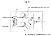
- a frequency component fs is extracted by nonlinearly processing a frequency component fs/2 (i.e., a frequency component which is 1/2 times a symbol rate fs) which is present in a digital modulated signal as symbol data changes.
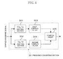
- the second complex filter 304 of FIG. 4 has the following frequency characteristics: the second complex filter 304 passes at least a frequency component +fs/4 therethrough, blocks a frequency component -fs/4 in order to prevent interference with the frequency component -fs/4 which is the output of the first complex filter 303, and also blocks frequency components ⁇ 3fs/4 which will become aliasing distortion components of frequency components ⁇ fs/2 by nonlinear processing in the subsequent stage.
- the second complex filter 304 filters the complex baseband signal according to these frequency characteristics, and supplies the resultant signal to the complex adder 305.
- This filtering operation is an operation of passing a frequency component +fs/2 and blocking zero frequency and frequency components -fs/2 and ⁇ fs in the complex baseband signal applied to the frequency converting section 30.
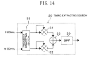
- the structure of the present embodiment enables stable timing extraction at the sampling clock frequency 2fs without being affected by a carrier frequency offset.
- each LPF 308, 309 can conduct the same, independent filtering operation to the I signal and the Q signal.
- the -fs/4 shifting section 310 shifts a zero frequency component to the frequency position -fs/4, shifts a null frequency component of fs to the frequency position 3fs/4, and shifts a null frequency component of fs/2 to the frequency position fs/4.
- the +fs/4 shifting section 311 shifts a zero frequency component to the frequency position fs/4, shifts a null frequency component of -fs to the frequency position -3fs/4, and shifts a null frequency component -fs/2 to the frequency position -fs/4.
- the BPF 312 extracts the frequency components ⁇ fs/2. Therefore, unnecessary frequency signal components can be removed in advance, thereby stabilizing timing extraction. Other specific effects are the same as those of the first embodiment.
- the overall structure of the present embodiment is the same as that of FIG. 1 except the structure of the timing extracting section 20 of FIG. 2.
- FIG. 12 shows the structure of the timing extracting section 20 of the present embodiment.
Landscapes
- Engineering & Computer Science (AREA)
- Computer Networks & Wireless Communication (AREA)
- Signal Processing (AREA)
- Digital Transmission Methods That Use Modulated Carrier Waves (AREA)
Applications Claiming Priority (2)
| Application Number | Priority Date | Filing Date | Title |
|---|---|---|---|
| JP2003273698 | 2003-07-11 | ||
| PCT/JP2004/008246 WO2005006694A1 (ja) | 2003-07-11 | 2004-06-07 | タイミング抽出装置及び方法並びにそのタイミング抽出装置を備えた復調装置 |
Publications (2)
| Publication Number | Publication Date |
|---|---|
| EP1643705A1 true EP1643705A1 (de) | 2006-04-05 |
| EP1643705A4 EP1643705A4 (de) | 2010-05-19 |
Family
ID=34056033
Family Applications (1)
| Application Number | Title | Priority Date | Filing Date |
|---|---|---|---|
| EP04736273A Withdrawn EP1643705A4 (de) | 2003-07-11 | 2004-06-07 | Timing-extraktionseinrichtung und verfahren und demodulationseinrichtung mit der timing-extraktionseinrichtung |
Country Status (7)
| Country | Link |
|---|---|
| US (1) | US7457375B2 (de) |
| EP (1) | EP1643705A4 (de) |
| JP (1) | JP3873078B2 (de) |
| KR (1) | KR100676568B1 (de) |
| CN (1) | CN100546294C (de) |
| TW (1) | TWI252624B (de) |
| WO (1) | WO2005006694A1 (de) |
Families Citing this family (5)
| Publication number | Priority date | Publication date | Assignee | Title |
|---|---|---|---|---|
| US8009723B2 (en) * | 2006-06-02 | 2011-08-30 | Terrace Communications Corporation | Measurement of baseband timing in a spread spectrum communications system |
| SG141257A1 (en) * | 2006-09-12 | 2008-04-28 | Oki Techno Ct Singapore Pte | Apparatus and method for demodulating a modulated signal |
| JP2011035557A (ja) * | 2009-07-30 | 2011-02-17 | Panasonic Corp | シンボルレート検出器及び受信装置 |
| US8965290B2 (en) * | 2012-03-29 | 2015-02-24 | General Electric Company | Amplitude enhanced frequency modulation |
| WO2019044195A1 (ja) | 2017-08-31 | 2019-03-07 | 株式会社村田製作所 | 心拍測定装置 |
Family Cites Families (13)
| Publication number | Priority date | Publication date | Assignee | Title |
|---|---|---|---|---|
| JPS6145658A (ja) | 1984-08-10 | 1986-03-05 | Nec Corp | タイミング位相制御方式 |
| JP2555140B2 (ja) | 1988-04-05 | 1996-11-20 | 株式会社日立製作所 | サンプリング位相制御装置 |
| JPH06120935A (ja) | 1991-02-18 | 1994-04-28 | Canon Inc | タイミング抽出装置 |
| JP2721454B2 (ja) | 1992-01-27 | 1998-03-04 | 富士通株式会社 | タイミング抽出方法 |
| JPH06104558A (ja) * | 1992-09-18 | 1994-04-15 | Toyota Motor Corp | 配線基板に対する電子部品パッケージの取付構造 |
| JP3369291B2 (ja) | 1994-02-15 | 2003-01-20 | 日本放送協会 | 位相誤差検出回路およびクロック再生回路 |
| US5495203A (en) * | 1994-12-02 | 1996-02-27 | Applied Signal Technology, Inc. | Efficient QAM equalizer/demodulator with non-integer sampling |
| CN1089508C (zh) * | 1995-01-27 | 2002-08-21 | 三洋电机株式会社 | 频率调制多重信号的接收电路 |
| JP3153792B2 (ja) | 1997-10-22 | 2001-04-09 | 松下電器産業株式会社 | Cdma同期回路及びcdma同期信号検出方法 |
| US6295325B1 (en) * | 1997-11-14 | 2001-09-25 | Agere Systems Guardian Corp. | Fixed clock based arbitrary symbol rate timing recovery loop |
| JP3792098B2 (ja) * | 2000-03-17 | 2006-06-28 | 三菱電機株式会社 | タイミング再生装置、これを用いた復調装置およびタイミング再生方法 |
| EP1168597A1 (de) * | 2000-06-23 | 2002-01-02 | NTT DoCoMo, Inc. | Quadraturempfänger mit Orthogonalitätskorrektur |
| US6690748B2 (en) * | 2001-07-06 | 2004-02-10 | Motorola, Inc. | Receiver with improved digital intermediate to base band demodulator |
-
2004
- 2004-06-07 EP EP04736273A patent/EP1643705A4/de not_active Withdrawn
- 2004-06-07 KR KR1020047020095A patent/KR100676568B1/ko not_active Expired - Fee Related
- 2004-06-07 US US10/520,616 patent/US7457375B2/en not_active Expired - Fee Related
- 2004-06-07 JP JP2005511488A patent/JP3873078B2/ja not_active Expired - Fee Related
- 2004-06-07 WO PCT/JP2004/008246 patent/WO2005006694A1/ja not_active Ceased
- 2004-06-07 CN CNB2004800003381A patent/CN100546294C/zh not_active Expired - Fee Related
- 2004-06-29 TW TW093119045A patent/TWI252624B/zh not_active IP Right Cessation
Also Published As
| Publication number | Publication date |
|---|---|
| TWI252624B (en) | 2006-04-01 |
| WO2005006694A1 (ja) | 2005-01-20 |
| CN100546294C (zh) | 2009-09-30 |
| CN1698333A (zh) | 2005-11-16 |
| US7457375B2 (en) | 2008-11-25 |
| JP3873078B2 (ja) | 2007-01-24 |
| JPWO2005006694A1 (ja) | 2006-08-31 |
| EP1643705A4 (de) | 2010-05-19 |
| US20050253742A1 (en) | 2005-11-17 |
| TW200514347A (en) | 2005-04-16 |
| KR20050042753A (ko) | 2005-05-10 |
| KR100676568B1 (ko) | 2007-01-30 |
Similar Documents
| Publication | Publication Date | Title |
|---|---|---|
| US4583048A (en) | MSK digital demodulator for burst communications | |
| US5588027A (en) | Digital demodulating method and circuit for use in a time-division multiple access channel | |
| EP0656706A2 (de) | Synchronisierung von OFDM-Signalen | |
| US7809086B2 (en) | Apparatus and methods for demodulating a signal | |
| JP3728573B2 (ja) | 復調装置 | |
| JP4366808B2 (ja) | タイミングエラー検出回路および復調回路とその方法 | |
| US4887280A (en) | System for detecting the presence of a signal of a particular data rate | |
| WO2000076163A1 (fr) | Comparateur de phase, lecteur chronometrique et demodulateur comprenant le comparateur de phase | |
| US6377634B1 (en) | Circuit for reproducing bit timing and method of reproducing bit timing | |
| EP3841674B1 (de) | Einzelkanalempfänger und empfangsverfahren | |
| US7457375B2 (en) | Timing extractor, timing extraction method, and demodulator having the timing extractor | |
| JP2931454B2 (ja) | ディジタル位相変調信号復調回路 | |
| KR19980021021A (ko) | 디지탈 록 검출회로 | |
| JPH0870332A (ja) | クロック再生装置 | |
| JP3088892B2 (ja) | データ受信装置 | |
| CN101366252A (zh) | 基于限幅器的模拟解调器 | |
| JP2765601B2 (ja) | 復調回路 | |
| JPH0897874A (ja) | オフセットqpsk復調器 | |
| JP4803079B2 (ja) | 復調装置 | |
| JPH1075275A (ja) | コスタスループ搬送波再生回路 | |
| KR19980015798A (ko) | 직각 위상 편이 복조기의 반송파 복원 장치 | |
| JP3382892B2 (ja) | 階層化伝送における位相変調信号をデジタル復調してフレーム同期パターン検出を行う方法及びその装置 | |
| JPH10210092A (ja) | 位相検波回路 | |
| WO2005107202A1 (ja) | タイミング再生回路および受信装置 | |
| JP3017757B2 (ja) | ベースバンド遅延検波器 |
Legal Events
| Date | Code | Title | Description |
|---|---|---|---|
| PUAI | Public reference made under article 153(3) epc to a published international application that has entered the european phase |
Free format text: ORIGINAL CODE: 0009012 |
|
| 17P | Request for examination filed |
Effective date: 20050112 |
|
| AK | Designated contracting states |
Kind code of ref document: A1 Designated state(s): DE FR GB NL |
|
| DAX | Request for extension of the european patent (deleted) | ||
| RBV | Designated contracting states (corrected) |
Designated state(s): DE FR GB NL |
|
| RAP1 | Party data changed (applicant data changed or rights of an application transferred) |
Owner name: PANASONIC CORPORATION |
|
| A4 | Supplementary search report drawn up and despatched |
Effective date: 20100415 |
|
| STAA | Information on the status of an ep patent application or granted ep patent |
Free format text: STATUS: THE APPLICATION IS DEEMED TO BE WITHDRAWN |
|
| 18D | Application deemed to be withdrawn |
Effective date: 20100821 |