EP1645239A1 - Dispositif de guidage d'électrodes à pointe froide - Google Patents
Dispositif de guidage d'électrodes à pointe froide Download PDFInfo
- Publication number
- EP1645239A1 EP1645239A1 EP05021936A EP05021936A EP1645239A1 EP 1645239 A1 EP1645239 A1 EP 1645239A1 EP 05021936 A EP05021936 A EP 05021936A EP 05021936 A EP05021936 A EP 05021936A EP 1645239 A1 EP1645239 A1 EP 1645239A1
- Authority
- EP
- European Patent Office
- Prior art keywords
- introducer
- holes
- rows
- clusters
- distal
- Prior art date
- Legal status (The legal status is an assumption and is not a legal conclusion. Google has not performed a legal analysis and makes no representation as to the accuracy of the status listed.)
- Granted
Links
- 238000002679 ablation Methods 0.000 claims abstract description 31
- 238000003780 insertion Methods 0.000 claims abstract description 4
- 230000037431 insertion Effects 0.000 claims abstract description 4
- 238000003491 array Methods 0.000 claims description 27
- 108091006146 Channels Proteins 0.000 claims description 16
- 239000012530 fluid Substances 0.000 claims description 16
- 239000002826 coolant Substances 0.000 claims description 15
- 238000004891 communication Methods 0.000 claims description 11
- 230000037361 pathway Effects 0.000 claims description 8
- 230000001427 coherent effect Effects 0.000 claims description 6
- 230000001939 inductive effect Effects 0.000 claims description 3
- 238000000034 method Methods 0.000 abstract description 18
- 210000000056 organ Anatomy 0.000 description 11
- 206010028980 Neoplasm Diseases 0.000 description 8
- 230000003902 lesion Effects 0.000 description 6
- 230000000694 effects Effects 0.000 description 5
- 238000010438 heat treatment Methods 0.000 description 4
- 238000001816 cooling Methods 0.000 description 3
- 238000002595 magnetic resonance imaging Methods 0.000 description 3
- 230000008569 process Effects 0.000 description 3
- 238000002591 computed tomography Methods 0.000 description 2
- 208000032843 Hemorrhage Diseases 0.000 description 1
- 230000005856 abnormality Effects 0.000 description 1
- 230000008901 benefit Effects 0.000 description 1
- 238000010276 construction Methods 0.000 description 1
- 239000012809 cooling fluid Substances 0.000 description 1
- 230000001351 cycling effect Effects 0.000 description 1
- 238000002059 diagnostic imaging Methods 0.000 description 1
- 239000011810 insulating material Substances 0.000 description 1
- 231100000518 lethal Toxicity 0.000 description 1
- 230000001665 lethal effect Effects 0.000 description 1
- 210000004185 liver Anatomy 0.000 description 1
- 239000012811 non-conductive material Substances 0.000 description 1
- 239000004033 plastic Substances 0.000 description 1
- 239000004417 polycarbonate Substances 0.000 description 1
- 229920000515 polycarbonate Polymers 0.000 description 1
- 230000007480 spreading Effects 0.000 description 1
- 238000001356 surgical procedure Methods 0.000 description 1
- 230000002459 sustained effect Effects 0.000 description 1
- 238000002604 ultrasonography Methods 0.000 description 1
- 238000012800 visualization Methods 0.000 description 1
Images




Classifications
-
- A—HUMAN NECESSITIES
- A61—MEDICAL OR VETERINARY SCIENCE; HYGIENE
- A61B—DIAGNOSIS; SURGERY; IDENTIFICATION
- A61B18/00—Surgical instruments, devices or methods for transferring non-mechanical forms of energy to or from the body
- A61B18/04—Surgical instruments, devices or methods for transferring non-mechanical forms of energy to or from the body by heating
- A61B18/12—Surgical instruments, devices or methods for transferring non-mechanical forms of energy to or from the body by heating by passing a current through the tissue to be heated, e.g. high-frequency current
- A61B18/14—Probes or electrodes therefor
- A61B18/1477—Needle-like probes
-
- A—HUMAN NECESSITIES
- A61—MEDICAL OR VETERINARY SCIENCE; HYGIENE
- A61B—DIAGNOSIS; SURGERY; IDENTIFICATION
- A61B18/00—Surgical instruments, devices or methods for transferring non-mechanical forms of energy to or from the body
- A61B2018/00053—Mechanical features of the instrument of device
- A61B2018/0016—Energy applicators arranged in a two- or three dimensional array
-
- A—HUMAN NECESSITIES
- A61—MEDICAL OR VETERINARY SCIENCE; HYGIENE
- A61B—DIAGNOSIS; SURGERY; IDENTIFICATION
- A61B18/00—Surgical instruments, devices or methods for transferring non-mechanical forms of energy to or from the body
- A61B18/04—Surgical instruments, devices or methods for transferring non-mechanical forms of energy to or from the body by heating
- A61B18/12—Surgical instruments, devices or methods for transferring non-mechanical forms of energy to or from the body by heating by passing a current through the tissue to be heated, e.g. high-frequency current
- A61B18/14—Probes or electrodes therefor
- A61B2018/1405—Electrodes having a specific shape
- A61B2018/1425—Needle
- A61B2018/143—Needle multiple needles
Definitions
- the present disclosure relates generally to cluster ablation electrode systems and, more particularly, to systems, devices and methods for positioning and placing multiple electrodes in a target surgical site.
- radiofrequency electrodes for ablation of tissue in a patient's body
- a radiofrequency electrode comprising an elongated, cylindrical shaft with a portion of its external surface insulated is inserted into the patient's body.
- the electrode typically has an exposed conductive tip, which is used to contact body tissue in the region where the heat lesion or ablation is desired.
- the electrode is connected to a radiofrequency power source, which provides radiofrequency voltage to the electrode, which transmits the radiofrequency current into the tissue near its exposed conductive tip. This current usually returns to the power source through a reference electrode, which may comprise a large area conductive contact connected to an external portion of the patient's body.
- multiple electrodes are inserted into the body in an array to enlarge ablation volumes.
- arrays of high frequency electrodes are inserted into tumors.
- the electrodes are typically placed in a dispersed fashion throughout the tumor volume to cover the tumor volume with uniform heat, typically below about 45°C.
- the electrodes may be sequentially applied with high frequency voltage so that each electrode heats in sequence its neighboring tissue and then shuts off. Then, the next electrode does the same in a time series. This sequence of cycling the voltage through the electrodes continues at a prescribed frequency and for a period of time.
- radiofrequency electrode tips With cooling, radiofrequency electrode tips generally produce larger lesion volumes compared with radiofrequency electrodes, which are not cooled.
- standard single cylindrical electrodes, with cooled tips, as described above may make lesion volumes up to 3 to 4 cm in diameter in living tissue (e.g., the liver) by using cannulae of 1 to 2 mm in diameter and having exposed tip lengths of several centimeters.
- a configuration of radiofrequency electrodes which can accomplish ablation in the range of 4 to 6 cm diameter or greater for the purpose of adequately treating large cancerous tumors in the body are necessary to effectively destroy the tumor and combat cancerous cells from spreading. It is further necessary that such an electrode system involve a simple geometry, reduced numbers of tissue insertions, facilitate planning of needle placement, and facilitate planning of heat ablation geometry and distribution.
- An electrode system which can be easily inserted into an organ or through the skin with minimal risk of hemorrhage and discomfort to the patient, is desirable.
- an introducer for facilitating the insertion of a cluster of electrodes into the body of a patient for tissue for performing tissue ablation.
- the introducer includes a body portion including a plurality of holes formed therein for selectively receiving a respective elongate shaft of the electrodes therethrough, wherein the holes of the introducer orient and space each electrode relative to one another, wherein the introducer includes a centrally disposed hole formed therein for receiving a guide needle therethrough.
- the introducer may further include a distal introducer including a plurality of arrays of hole clusters formed therein each arranged in a linear row, wherein the rows of hole clusters are equally spaced from one another; and a proximal introducer including a plurality of arrays of holes formed therein each arranged in a linear row, wherein the rows of holes are equally spaced from one another.
- each radial row of holes of the proximal introducer may be equally spaced from one another.
- the proximal introducer includes six arrays of holes formed, wherein the rows of holes of the proximal introducer alternate between rows of six holes and rows of seven holes.
- Each cluster of holes of the distal introducer may include a radially inner-most hole and a pair of radially outer-most holes.
- the radially outer-most holes may be offset an angle from an axis extending through the inner-most holes of each respective array of hole clusters.
- the inner-most holes of each radial row of clusters of the distal introducer may be equally spaced from one another.
- the distal introducer may include six arrays of clusters formed therein arranged in a linear row.
- the rows of clusters of the distal introducer may alternate between rows of six clusters and rows of seven clusters.
- the present disclosure relates to systems, devices and methods for positioning and placing multiple electrodes in a target surgical site.
- an electrode system for use with a high frequency generator to induce coherent high frequency heat ablation volumes within targeted tissue of a patient.
- the electrode system includes a hub; and at least three electrodes.
- Each electrode includes a substantially rigid elongated shaft extending from the hub and terminating in a sealed distal end section having an exposed conductive tip portion configured to be inserted into the targeted tissue and adapted at a proximal end section to be coupled to a high frequency generator to simultaneously apply an equal output voltage to each of the exposed conductive tip portions.
- Each electrode further includes a closed-loop fluid communication channel pathway which includes an inflow opening adapted for connection to a coolant fluid supply, and a channel portion in fluid communication with the inflow opening.
- the channel; portion extends distally inside the conductive tip portion to carry coolant to the inside of the conductive tip portion and further extends proximally back to an outlet opening adapted to carry coolant away from the conductive tip portion.
- the electrode system further includes an introducer including a plurality of holes formed therein for selectively receiving a respective elongate shaft of the electrodes therethrough.
- the holes of the introducer orient and space each electrode relative to one another.
- the introducer includes a centrally disposed hole formed therein for receiving a guide needle therethrough.
- the conductive tip portions of the at least three electrodes may be arrayed relative to each other in a predetermined non-linear geometric spatial relationship relative to a longitudinal axis of the instrument such that upon application of an output voltage to the conductive tip portions, a coherent ablation isotherm is generated which encloses a desired target volume of the tissue to induce a large heat ablation volume.
- the electrode receiving holes of the introducer are each equally spaced from the central hole of the introducer.
- Each electrode receiving hole of the introducer includes a longitudinal axis which is parallel to one another.
- the electrode system includes a distal introducer and a proximal introducer.
- the distal introducer and the proximal introducer may each include a central hole formed therein for selectively receiving a guide needle therethrough, wherein the central holes function to align the distal and proximal introducers with one another.
- the proximal introducer may include a plurality of arrays of holes formed therein each arranged in a linear row.
- the rows of holes are desirably equally spaced from one another.
- each radial row of holes of the proximal introducer is equally spaced from one another.
- the proximal introducer includes six arrays of holes formed therein arranged in a linear row.
- the rows of holes of the proximal introducer alternate between rows of six holes and rows of seven holes.
- the distal introducer includes a plurality of arrays of hole clusters formed therein each arranged in a linear row.
- the rows of hole clusters are desirably equally spaced from one another.
- Each cluster of holes of the distal introducer may include a radially inner-most hole and a pair of radially outer-most holes.
- the radially outer-most holes may be offset an angle from an axis extending through the inner-most holes of each respective array of hole clusters.
- each radial row of clusters of the distal introducer is equally spaced from one another.
- the distal introducer includes six arrays of clusters formed therein arranged in a linear row. The rows of clusters of the distal introducer alternate between rows of six clusters and rows of seven clusters.
- a system for inducing enlargement of heat ablation volumes within tissue of a patient's body includes a high frequency generator for supplying an output voltage; at least three substantially rigid, elongated electrodes adapted to be inserted into the tissue of a patient's body; and an introducer including a plurality of holes formed therein for selectively receiving a respective elongate shaft of the electrodes therethrough.
- Each of the at least three electrodes has exposed conductive tip portions arranged in a predetermined parallel relationship and a closed-loop fluid communication channel pathway.
- the channel pathway includes an inflow opening adapted for connection to a coolant fluid supply, and a channel portion in fluid communication with the inflow opening.
- the channel portion extends distally inside the conductive tip portion to carry coolant to the inside of the conductive tip portion and further extends proximally back to an outlet opening adapted to carry coolant away from the conductive tip portion.
- the holes of the introducer orient and space each electrode relative to one another.
- the introducer includes a centrally disposed hole formed therein for receiving a guide needle therethrough.
- the introducer includes a distal introducer including a plurality of arrays of hole clusters formed therein each arranged in a linear row, wherein the rows of hole clusters are equally spaced from one another; and a proximal introducer including a plurality of arrays of holes formed therein each arranged in a linear row, wherein the rows of holes are equally spaced from one another.
- the holes of each radial row of holes of the proximal introducer may be equally spaced from one another.
- the proximal introducer may include six arrays of holes formed. The rows of holes of the proximal introducer alternate between rows of six holes and rows of seven holes.
- Each cluster of holes of the distal introducer may include a radially inner-most hole and a pair of radially outer-most holes, wherein the radially outer-most holes may be offset an angle from an axis extending through the inner-most holes of each respective array of hole clusters.
- the inner-most holes of each radial row of clusters of the distal introducer may be equally spaced from one another.
- the distal introducer may include six arrays of clusters formed therein arranged in a linear row. The rows of clusters of the distal introducer may alternate between rows of six clusters and rows of seven clusters.
- a process for heat ablation of tissue in a patient includes the steps of providing an electrode system for inducing enlargement of heat ablation volumes within tissue of a patient's body.
- the electrode system includes a high frequency generator for supplying an output voltage; at least three substantially rigid, elongated electrodes adapted to be inserted into the tissue of a patient's body; and an introducer including a plurality of holes formed therein for selectively receiving a respective elongate shaft of the electrodes therethrough.
- Each of the at least three electrodes has an exposed conductive tip portion arranged in a predetermined parallel relationship and a closed-loop fluid communication channel pathway.
- the channel pathway includes an inflow opening adapted for connection to a coolant fluid supply, and a channel portion in fluid communication with the inflow opening.
- the channel portion extends distally inside the conductive tip portion to carry coolant to the inside of the conductive tip portion and further extends proximally back to an outlet opening adapted to carry coolant away from the conductive tip portion.
- the holes of the introducer orient and space each electrode relative to one another.
- the introducer includes a centrally disposed hole formed therein for receiving a guide needle therethrough.
- the method further includes inserting the electrodes into desired holes of the introducer in order to position each electrode relative to one another; inserting the electrodes into the tissue; applying substantially the same radiofrequency output through the electrodes to a targeted tissue volume to produce coherent heating of the targeted tissue volume; raising the radiofrequency output to a level that induces enlargement of the volume of heat ablation in the tissue near the electrodes; and cooling each electrode by circulating a cooling fluid through a closed-loop fluid communication channel pathway formed in each of the electrodes.
- the introducer includes a distal introducer including a plurality of arrays of hole clusters formed therein each arranged in a linear row, wherein the rows of hole clusters are equally spaced from one another; and a proximal introducer including a plurality of arrays of holes formed therein each arranged in a linear row, wherein the rows of holes are equally spaced from one another.
- the method further includes the steps of placing the electrodes into desired holes of the proximal introducer; placing the distal introducer in a desired position on the skin surface of the patient; introducing the electrodes into the patient through the holes provided in the distal introducer; and advancing the electrodes through the distal introducer.
- the method may further include the steps of placing a guide needle into a central hole formed in the distal introducer; inserting the guide needle into the body of the patient such that a tip of the guide needle is placed in close proximity to a target tissue; and placing the distal introducer against the skin of the patient.
- the method may further include the steps of withdrawing the guide needle from the distal introducer; and inserting the electrodes into the body of the patient through the holes formed in the distal introducer.
- the method may still further include the step of advancing the electrodes through the distal introducer until the tips thereof are in close proximity to the target tissue.
- FIG. 1 is a schematic illustration of an ablation electrode array system according to the present disclosure showing multiple radiofrequency electrodes being positioned in a patient's organ for producing heat ablation of a targeted tissue area;
- FIG. 2 is a perspective view of an electrode introducer according to an embodiment of the present disclosure
- FIG. 3 is a perspective view of the electrode introducer of FIG. 2 including a needle extending therefrom;
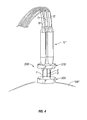
- FIG. 4 is a perspective view of the electrode array system of FIG. 1 including a two piece combined electrode introducer according to another embodiment of the present disclosure
- FIG. 5 is a perspective view of a first electrode introducer of the two piece combined electrode introducer shown in FIG. 4;
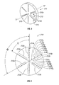
- FIG. 6 is a top plan view of the first electrode introducer of FIG. 5;
- FIG. 7 is a perspective view of a second electrode introducer of the two piece combined electrode introducer shown in FIG. 4;
- FIG. 8 is a top plan view of the second electrode introducer shown in FIG. 7;
- FIG. 9 is an enlarged view of the indicated area of detail of FIG. 8.
- Electrode array system “E” includes a plurality of electrodes 1, 2 and 3, which are to be inserted into an organ “OR” of a human body or any other body tissue. Respective distal tips 1b, 2b and 3b of electrodes 1, 2 and 3 are un-insulated and conductively exposed so that electrical currents induce heating within the tissue or organ "OR”.
- a targeted volume of tissue “T” is shown in sectional view and may represent, for example, a tumor or other abnormality in a human body.
- Electrodes 1, 2 and 3 are connected by respective wires or cables 10, 11 and 12 to an electrosurgical generator 16.
- Electrosurgical generator 16 may be a radiofrequency or high frequency type generator.
- Electrosurgical generator 16 includes control elements, illustrated by block 17, which may, for example, increase the radiofrequency power output of electrodes 1, 2 and 3, control temperature when electrode array system "E" or satellite sensors (not shown) include temperature sensors, monitor or control impedance, power, current, voltage, or other output parameters.
- Electrosurgical generator 16 may include a display or screen, illustrated by block 18, within it or as a separate system, for providing a display of heating parameters such as temperature for one or more of electrodes 1, 2 and 3, impedance, power, current, or voltage of the radiofrequency output. Such individual display readings are illustrated by the reference letters R1 ... RN.
- Electrode system “E” further includes a reference electrode 19, which may be placed in contact with the skin of a patient or an external surface of organ “OR” with a connection 20 to electrosurgical generator 16.
- Reference electrode 19 and connection 20 serves as a path for return current from electrosurgical generator 16 through electrodes 1, 2 and 3.
- Each electrode 1, 2 and 3 includes a rigid shaft 1a, 2a and 3a, respectively, which enables electrodes 1, 2 and 3 to be easily urged into the body tissue or organ "OR".
- Each electrode 1, 2 and 3 terminates pointed distal tips 1b, 2b and 3b, respectively.
- a portion of the external surface of each electrode 1, 2 and 3 is covered with an insulating material, as indicated by hatched line areas in FIG. 1.
- Distal tips 1b, 2b and 3b are connected, through respective shafts 1a, 2a and 3a to cables 10, 11 and 12, respectively, and thereby to electrosurgical generator 16.
- electrosurgical generator 16 may be a radiofrequency generator with frequency between about 100 kilohertz (kHz) to several hundred megahertz (MHz). Additionally, electrosurgical generator 16 may have power output ranging from several watts to several hundred watts, depending on the clinical application.
- electrodes 1, 2 and 3 may be raised to the same radiofrequency voltage potential from electrosurgical generator 16.
- the array of electrodes thus becomes, in effect, a larger, coherent electrode including the individual electrode tips 1b, 2b and 3b.
- the heating effect of the array of electrodes is substantially similar to that achieved by one large single electrode.
- a targeted region to be ablated is represented in sectional view by the line "T". It is desired to ablate the targeted region "T” by fully engulfing targeted region “T” in a volume of lethal heat elevation.
- the targeted region "T” may be, for example, a tumor which has been detected by an image scanner 30.
- CT, MRI, or ultrasonic image scanners may be used, and the image data transferred to a computer 26.
- an ultrasonic scanner head 15 may be disposed in contact with organ "OR” to provide an image illustrated by lines 15A.
- a data processor 16 may be connected to the display devices to visualize targeted region "T" and/or ablation zone "T1" in real time during the ablation procedure.
- the image representation of the scan may be displayed on display unit 22 to represent the size and position of target region "T". Placement of electrodes 1, 2 and 3 may be predetermined based on such image data as interactively determined by real-time scanning of organ "OR”. Electrodes 1, 2 and 3 are inserted into the tissue by freehand technique by a guide block or introducer 100 with multi-hole templates, or by stereotactic frame or frameless guidance, as known by those skilled in the art.
- an array of electrodes 1, 2 and 3 are connected to the same radiofrequency voltage from electrosurgical generator 16. Accordingly, the array of electrodes 1, 2 and 3 will act as a single effectively larger electrode.
- the relative position and orientation of electrodes 1, 2 and 3 enable the creation of different shapes and sizes of ablation volumes.
- dashed line 8 represents the ablation isotherm in a sectional view through organ "OR".
- Such an ablation isotherm may be that of the surface achieving possible temperatures of approximately 50°C or greater. At that temperature range, sustained for approximately 30 seconds to approximately several minutes, tissue cells will be ablated.
- the shape and size of the ablation volume may accordingly be controlled by the configuration of the electrode array, the geometry of the distal tips 1b, 2b and 3b of electrodes 1, 2 and 3, respectively, the amount of RF power applied, the time duration that the power is applied, cooling of the electrodes, etc.
- Introducer 100 includes a plurality of electrode through-holes 102 formed therein.
- introducer 100 includes a first set of three holes 102a, 102b and 102c formed therein.
- holes 102a, 102b and 102c are spaced an equal distance apart from one another.
- holes 102a, 102b and 102c define an equilateral triangle.
- Each hole 102a, 102b and 102c defines a longitudinal axis "Xa, Xb and Xc".
- longitudinal axes "Xa, Xb and Xc" are at least substantially parallel to one another.
- holes 102a, 102b and 102c are sized and dimensioned to slidably receive a respective electrode 1, 2 and 3 therein.
- introducer 100 further includes a central hole 104 formed therethrough.
- Central hole 104 defines a central longitudinal axis "X".
- the central longitudinal "X" axis is at least substantially parallel to the longitudinal axes "Xa, Xb and Xc" of holes 102a, 102b and 102c.
- central hole 104 is located at the intersection of axes or lines extending orthogonally through the longitudinal axes "Xa, Xb and Xc" of holes 102a, 102b and 102c.
- introducer 100 may have a substantially triangular geometric configuration including corners 106a, 106b and 106c and side walls 108a, 108b and 108c. It is envisioned that a hole 102a, 102b and 102c is formed near a respective corner 106a, 106b and 106c of introducer 100. Desirably, each corner 106a, 106b and 106c of introducer 100 is rounded or radiused. Additionally, side walls 108a, 108b and 108c may be planar and, desirably, as seen in FIGS. 2 and 3, may be concave.
- introducer 100 functions to hold or maintain electrodes 1, 2 and 3 of electrode system "E" substantially parallel to one another and at a defined distance from one another during the use thereof. It is envisioned that a guide needle 110 may be advanced through center hole 104 of introducer 100 and advanced to the desired target tissue using known medical imaging techniques (e.g., ultrasound, computer tomography, magnetic resonance imaging, X-ray, CT scan, etc.)
- known medical imaging techniques e.g., ultrasound, computer tomography, magnetic resonance imaging, X-ray, CT scan, etc.
- center hole 104 may be eliminated and guide needle 110 may be operatively secured to the center of introducer 100 (i.e., at the central longitudinal "X" axis).
- introducer 100 may be introduced or advanced to the target tissue in a manner similar to that described above.
- an introducer in accordance with an alternative embodiment of the present disclosure, is generally designated as 200 and is shown in operative association with a cluster electrode system "E".
- Introducer 200 includes a first or proximal introducer 210 and a second or distal introducer 220.
- proximal introducer 210 and distal introducer 220 are used in cooperation with or in combination with one another to hold or maintain electrodes 1, 2 and 3 of electrode system "E" substantially parallel to one another, at a defined distance from one another and/or at a defines location relative to one another during the use thereof.
- proximal introducer 210 includes a plurality of radially oriented rows 212 of holes 214 formed therein.
- each row 212 is equally spaced from one another by an angle " ⁇ " relative to one another.
- proximal introducer 210 may include six (6) rows 212 of holes 214 which are spaced from one another by an angle " ⁇ " approximately equal to 60°.
- each hole 214 includes a longitudinal axis which is at least substantially parallel to one another.
- each hole 214 may have a diameter of approximately 0.085 in. (2.16mm)
- Proximal introducer 210 further includes a central hole 216 formed therethrough.
- Central hole 216 defines a central longitudinal axis "X".
- the central longitudinal "X" axis is at least substantially parallel to the longitudinal axes of holes 214.
- central hole 216 is located at the intersection of rows 212.
- a first set of rows 212a includes six (6) holes 214a formed therealong. Desirably, rows 212a of holes 214a are spaced from one another by an angle " ⁇ " approximately equal to 120°.
- a second set or rows 212b includes seven (7) holes 214b formed therealong. Desirably, rows 212b of holes 214b are spaced from one another by an angle " ⁇ " approximately equal to 120°.
- the respective holes 214a of the first set of rows 212a define an equilateral triangle therebetween.
- the distance between respective inner-most holes 214a 1 is approximately 0.984 in. (25.0 mm).
- the distance between respective second inner-most holes 214a 2 is approximately 1.378 in. (35.0 mm).
- the distance between respective third inner-most holes 214a 3 is approximately 1.772 in. (45.0 mm).
- the distance between respective fourth inner-most holes 214a 4 is approximately 2.165 in. (55.0 mm).
- the distance between respective fifth inner-most holes 214a 5 is approximately 2.559 in. (65.0 mm).
- the distance between respective sixth inner-most holes 214a 6 is approximately 2.953 in. (75.0 mm).
- the respective holes 214b of the second set of rows 212b also define an equilateral triangle therebetween.
- the distance between respective inner-most holes 214b 1 is approximately 0.787 in. (20.0 mm).
- the distance between respective second inner-most holes 214b 2 is approximately 1.181 in. (30.0 mm).
- the distance between respective third inner-most holes 214b3 is approximately 1.575 in. (40.0 mm).
- the distance between respective fourth inner-most holes 214b 4 is approximately 1.969 in. (50.0 mm).
- the distance between respective fifth inner-most holes 214b 5 is approximately 2.362 in. (60.0 mm).
- the distance between respective sixth inner-most holes 214b 6 is approximately 2.756 in. (70.0 mm).
- the distance between respective seventh inner-most holes 214b 7 is approximately 3.150 in. (80.0 mm).
- proximal introducer 210 may have a substantially circular geometric profile.
- proximal introducer 210 may have a diameter approximately 4.0 in. (102.0 mm). It is further envisioned that proximal introducer 210 may have a thickness of approximately 0.38 in. (9.65 mm).
- distal introducer 220 is similar to proximal introducer 210 and will only be discussed in detail to the extent necessary to identify differences in construction and operation.
- Distal introducer 220 includes a plurality of radially oriented rows 222 of holes 224 formed therein.
- distal introducer 220 includes six (6) rows 222 of holes 224 which are spaced from one another by an angle " ⁇ " of approximately 60°.
- each hole 224 may have a diameter of approximately 0.085 in. (2.16mm).
- the number and location of holes 224 of distal introducer 220 is substantially identical to the number and location of holes 214 of proximal introducer 210.
- a first set of rows 222a includes six (6) holes 224a formed therealong. Desirably, rows 222a of holes 224a are spaced from one another by an angle " ⁇ " of approximately 120°.
- a second set or rows 222b includes seven (7) holes 224b formed therealong. Desirably, rows 222b of holes 224b are spaced from one another by an angle " ⁇ " of approximately 120°.
- Central hole 226 defines a central longitudinal axis "X".
- the central longitudinal "X" axis is at least substantially parallel to the longitudinal axes of holes 224.
- central hole 226 is located at the intersection of rows 222.
- distal introducer 220 further includes rows 223a and 225a of holes 226a formed on either side of each row of holes 224a the first set of rows 222a and rows 223b and 225b of holes 226b formed on either side of each row of holes 224b of the second set of rows 222b.
- each row 223a and 225a includes six (6) holes corresponding, one each, to holes 224a for each row 222a.
- each row 223b and 225b desirably includes seven (7) holes corresponding, one each, to holes 224b for each row 222b.
- holes 226a, of rows 223a and 225a, and holes 226b, of rows 223b and 225b are offset a radial distance outward from corresponding holes 224a and 224b, respectively.
- a central axis of each hole 226a is desirably spaced a distance "d" from a central axis of a corresponding hole 224b of the first set or rows 222b by an amount of approximately 0.198 in. (5.0 mm) at an angle " ⁇ " of approximately 30.00° relative to an axis "R" extending radially through holes 224b (e.g., a diameter or radius of distal introducer 220).
- radially outer-most holes 226b of rows 223b and 225b and radially outer-most hole 224b of row 222b define a cluster "C" with holes 224b and 226b is a substantially equilateral configuration.
- cluster "C” may receive three smaller or thinner needles to achieve the same effect as compared to a single larger needle.
- a plurality of clusters "C” are desirably defines along each row 222a and 222b.
- a central axis of each hole 226b is also spaced a distance "d" from a central axis of a corresponding hole 224b of the second set or rows 222b by an amount of approximately 0.198 in. (5.0 mm) at an angle " ⁇ " of approximately equal to 29.67° relative to an axis "R” extending radially through holes 224a (e.g., a diameter or radius of distal introducer 220).
- distal introducer 220 may have a substantially circular geometric profile.
- distal introducer 220 may have a diameter of approximately 4.0 in. (102.0 mm). It is further envisioned that distal introducer 220 may have a thickness of approximately 0.375 in. (9.925 mm). While a circular geometric profile is shown, it is envisioned and within the scope of the present disclosure that any geometric profile may be used, such as, for example, hexagonal, rectangular, star-shaped, etc.
- proximal introducer 210 and distal introducer 220 may be fabricated from a rigid, non-conductive material (e.g., plastic, polycarbonate, etc.).
- electrodes 1, 2 and 3 of electrode array system "E” are positioned in holes 214a of rows 212a or in holes 214b of rows 212b, depending on the particular surgical procedure and depending on the size and characteristics of the organ to be operated on. Desirably, electrodes 1, 2 and 3 are placed solely in corresponding holes 214a of rows 212a or in holes 214b of rows 212b. Desirably, electrodes 1, 2 and 3 are positioned in introducer 210 in substantially equilateral triangular configurations. Depending on the size of the target lesion and the particular operative parameters to be employed and/or delivered from electrosurgical generator 16, electrodes 1, 2 and 3 may be placed in holes 214a or 214b which are either closer or further from central hole 216.
- distal introducer 220 Prior to, concomitantly therewith, or subsequent thereto, distal introducer 220 is placed against the body surface of the patient at a location in the proximity to where electrodes 1, 2 and 3 are to be introduced into the body. Desirably, a guide needle 110 (see FIG. 3) extending from the center of distal introducer 220 may be used to position the location of distal introducer 220 relative to the body surface of the patient.
- electrodes 1, 2 and 3 of electrode array system “E” With the relative distance and orientation of electrodes 1, 2 and 3 of electrode array system “E” set by proximal introducer 210 and with distal introducer 220 positioned against the body surface of the patient, electrodes 1, 2 and 3 of electrode array system “E” are then inserted into desired and/or pre-determined holes 224a, 224b of rows 222a or 222b, respectively, or into desires and/or predetermined holes 226a, 226b of rows 223a, 225a or rows 223b, 225b.
- Introducer 200 including proximal introducer 210 and distal introducer 220 help to facilitate placement of electrodes 1, 2 and 3 of electrode array system "E" by the clinician.
- introducer 200 may function to maintain electrodes 1, 2 and 3 substantially parallel to one another, and at a prescribed spacing relative to one another. The prescribed spacing is determined in part by the energy delivery to the organ which may have an effect on the overall size of the lesion. Additionally, introducer 200 and, in certain instances guide needle 110, aid the clinician in holding electrodes 1, 2 and 3 at the appropriate and/or desired depth and at a substantially equal depth to one another.
- Voltage variations or phases between electrodes may be implemented to achieve desired temperature distribution in the tissue as monitored by temperature sensors in the tissue or by visualization of temperature distribution using thermally sensitive MRI scanning, for example. Accordingly, the choice of electrical output type, sequence, and levels and the distribution of the electrodes of the array should be considered to have wide variations within the scope of the present disclosure.
Landscapes
- Health & Medical Sciences (AREA)
- Surgery (AREA)
- Engineering & Computer Science (AREA)
- Life Sciences & Earth Sciences (AREA)
- Biomedical Technology (AREA)
- Otolaryngology (AREA)
- Nuclear Medicine, Radiotherapy & Molecular Imaging (AREA)
- Plasma & Fusion (AREA)
- Physics & Mathematics (AREA)
- Heart & Thoracic Surgery (AREA)
- Medical Informatics (AREA)
- Molecular Biology (AREA)
- Animal Behavior & Ethology (AREA)
- General Health & Medical Sciences (AREA)
- Public Health (AREA)
- Veterinary Medicine (AREA)
- Surgical Instruments (AREA)
Applications Claiming Priority (1)
| Application Number | Priority Date | Filing Date | Title |
|---|---|---|---|
| US61733704P | 2004-10-08 | 2004-10-08 |
Publications (2)
| Publication Number | Publication Date |
|---|---|
| EP1645239A1 true EP1645239A1 (fr) | 2006-04-12 |
| EP1645239B1 EP1645239B1 (fr) | 2011-06-15 |
Family
ID=35530796
Family Applications (1)
| Application Number | Title | Priority Date | Filing Date |
|---|---|---|---|
| EP05021936A Expired - Lifetime EP1645239B1 (fr) | 2004-10-08 | 2005-10-07 | Dispositif de guidage d'électrodes |
Country Status (5)
| Country | Link |
|---|---|
| US (2) | US7776035B2 (fr) |
| EP (1) | EP1645239B1 (fr) |
| AU (1) | AU2005220217B2 (fr) |
| CA (1) | CA2522314A1 (fr) |
| ES (1) | ES2367645T3 (fr) |
Cited By (3)
| Publication number | Priority date | Publication date | Assignee | Title |
|---|---|---|---|---|
| DE102007042524A1 (de) * | 2007-09-07 | 2009-03-12 | Celon Ag Medical Instruments | Koagulationsschablone und Applikationsvorrichtung |
| EP2366352A1 (fr) * | 2010-03-19 | 2011-09-21 | Vesalius Medical Technologies Bvba | Dispositif et procédé pour ablation par radiofréquence |
| WO2024009840A1 (fr) * | 2022-07-04 | 2024-01-11 | 株式会社トップ | Couvercle de base d'aiguille et dispositif de traitement haute fréquence |
Families Citing this family (70)
| Publication number | Priority date | Publication date | Assignee | Title |
|---|---|---|---|---|
| US6478793B1 (en) | 1999-06-11 | 2002-11-12 | Sherwood Services Ag | Ablation treatment of bone metastases |
| AR038658A1 (es) * | 2001-06-15 | 2005-01-26 | Novartis Ag | Derivados de 4-aril-2(1h) quinazolinona y 4-aril-quinazolina 2-sustituidas, un proceso para su preparacion, composiciones farmaceuticas y el uso de dichos derivados para la preparacion de un medicamento |
| GB2403148C2 (en) | 2003-06-23 | 2013-02-13 | Microsulis Ltd | Radiation applicator |
| WO2005096979A1 (fr) | 2004-04-01 | 2005-10-20 | The General Hospital Corporation | Procede et appareil de traitement dermatologique et remodelage de tissus |
| GB2415630C2 (en) | 2004-07-02 | 2007-03-22 | Microsulis Ltd | Radiation applicator and method of radiating tissue |
| US7553309B2 (en) * | 2004-10-08 | 2009-06-30 | Covidien Ag | Electrosurgical system employing multiple electrodes and method thereof |
| US7282049B2 (en) | 2004-10-08 | 2007-10-16 | Sherwood Services Ag | Electrosurgical system employing multiple electrodes and method thereof |
| US7776035B2 (en) | 2004-10-08 | 2010-08-17 | Covidien Ag | Cool-tip combined electrode introducer |
| US7467075B2 (en) * | 2004-12-23 | 2008-12-16 | Covidien Ag | Three-dimensional finite-element code for electrosurgery and thermal ablation simulations |
| US20070066971A1 (en) * | 2005-09-21 | 2007-03-22 | Podhajsky Ronald J | Method and system for treating pain during an electrosurgical procedure |
| US7879031B2 (en) * | 2005-09-27 | 2011-02-01 | Covidien Ag | Cooled RF ablation needle |
| US20070078454A1 (en) * | 2005-09-30 | 2007-04-05 | Mcpherson James W | System and method for creating lesions using bipolar electrodes |
| US8795270B2 (en) * | 2006-04-24 | 2014-08-05 | Covidien Ag | System and method for ablating tissue |
| US20070258838A1 (en) * | 2006-05-03 | 2007-11-08 | Sherwood Services Ag | Peristaltic cooling pump system |
| US20070260240A1 (en) | 2006-05-05 | 2007-11-08 | Sherwood Services Ag | Soft tissue RF transection and resection device |
| US7763018B2 (en) * | 2006-07-28 | 2010-07-27 | Covidien Ag | Cool-tip thermocouple including two-piece hub |
| US8211099B2 (en) | 2007-01-31 | 2012-07-03 | Tyco Healthcare Group Lp | Thermal feedback systems and methods of using the same |
| US7655004B2 (en) | 2007-02-15 | 2010-02-02 | Ethicon Endo-Surgery, Inc. | Electroporation ablation apparatus, system, and method |
| US9486269B2 (en) * | 2007-06-22 | 2016-11-08 | Covidien Lp | Electrosurgical systems and cartridges for use therewith |
| US8181995B2 (en) * | 2007-09-07 | 2012-05-22 | Tyco Healthcare Group Lp | Cool tip junction |
| US8292880B2 (en) | 2007-11-27 | 2012-10-23 | Vivant Medical, Inc. | Targeted cooling of deployable microwave antenna |
| US8888792B2 (en) | 2008-07-14 | 2014-11-18 | Ethicon Endo-Surgery, Inc. | Tissue apposition clip application devices and methods |
| US8608739B2 (en) | 2008-07-22 | 2013-12-17 | Covidien Lp | Electrosurgical devices, systems and methods of using the same |
| US8157834B2 (en) | 2008-11-25 | 2012-04-17 | Ethicon Endo-Surgery, Inc. | Rotational coupling device for surgical instrument with flexible actuators |
| US8361066B2 (en) | 2009-01-12 | 2013-01-29 | Ethicon Endo-Surgery, Inc. | Electrical ablation devices |
| US20100256735A1 (en) * | 2009-04-03 | 2010-10-07 | Board Of Regents, The University Of Texas System | Intraluminal stent with seam |
| US8632534B2 (en) | 2009-04-03 | 2014-01-21 | Angiodynamics, Inc. | Irreversible electroporation (IRE) for congestive obstructive pulmonary disease (COPD) |
| US9107666B2 (en) | 2009-04-17 | 2015-08-18 | Domain Surgical, Inc. | Thermal resecting loop |
| US9265556B2 (en) | 2009-04-17 | 2016-02-23 | Domain Surgical, Inc. | Thermally adjustable surgical tool, balloon catheters and sculpting of biologic materials |
| US9078655B2 (en) | 2009-04-17 | 2015-07-14 | Domain Surgical, Inc. | Heated balloon catheter |
| US9131977B2 (en) | 2009-04-17 | 2015-09-15 | Domain Surgical, Inc. | Layered ferromagnetic coated conductor thermal surgical tool |
| US8372066B2 (en) | 2009-04-17 | 2013-02-12 | Domain Surgical, Inc. | Inductively heated multi-mode surgical tool |
| CA2761652C (fr) * | 2009-05-11 | 2019-10-01 | Leigh E. Colby | Ablation therapeutique de bourgeon dentaire |
| US10022202B2 (en) | 2013-03-15 | 2018-07-17 | Triagenics, Llc | Therapeutic tooth bud ablation |
| US12514679B2 (en) | 2009-05-11 | 2026-01-06 | TriAgenics, Inc. | Therapeutic tooth bud ablation |
| WO2014143014A1 (fr) | 2013-03-15 | 2014-09-18 | Triagenics, Llc | Ablation thérapeutique de bourgeon dentaire |
| WO2010138919A2 (fr) | 2009-05-28 | 2010-12-02 | Angiodynamics, Inc. | Système et méthode de synchronisation de l'apport d'énergie et du rythme cardiaque |
| US9895189B2 (en) | 2009-06-19 | 2018-02-20 | Angiodynamics, Inc. | Methods of sterilization and treating infection using irreversible electroporation |
| GB2474233A (en) | 2009-10-06 | 2011-04-13 | Uk Investments Associates Llc | Cooling pump comprising a detachable head portion |
| US20110098704A1 (en) | 2009-10-28 | 2011-04-28 | Ethicon Endo-Surgery, Inc. | Electrical ablation devices |
| US9028483B2 (en) | 2009-12-18 | 2015-05-12 | Ethicon Endo-Surgery, Inc. | Surgical instrument comprising an electrode |
| US8764744B2 (en) | 2010-01-25 | 2014-07-01 | Covidien Lp | System for monitoring ablation size |
| EP2627274B1 (fr) | 2010-10-13 | 2022-12-14 | AngioDynamics, Inc. | Système d'ablation électrique des tissus chez un patient |
| US9254169B2 (en) | 2011-02-28 | 2016-02-09 | Ethicon Endo-Surgery, Inc. | Electrical ablation devices and methods |
| US9233241B2 (en) | 2011-02-28 | 2016-01-12 | Ethicon Endo-Surgery, Inc. | Electrical ablation devices and methods |
| US9049987B2 (en) | 2011-03-17 | 2015-06-09 | Ethicon Endo-Surgery, Inc. | Hand held surgical device for manipulating an internal magnet assembly within a patient |
| US20140148802A1 (en) * | 2011-07-28 | 2014-05-29 | Charles LeMay | Radio Frequency Procedure Protection |
| US9526558B2 (en) | 2011-09-13 | 2016-12-27 | Domain Surgical, Inc. | Sealing and/or cutting instrument |
| US9078665B2 (en) | 2011-09-28 | 2015-07-14 | Angiodynamics, Inc. | Multiple treatment zone ablation probe |
| JP2015506729A (ja) | 2011-12-06 | 2015-03-05 | ドメイン・サージカル,インコーポレーテッド | 外科手術器具への電力供給を制御するシステム及び方法 |
| US9414881B2 (en) | 2012-02-08 | 2016-08-16 | Angiodynamics, Inc. | System and method for increasing a target zone for electrical ablation |
| US9427255B2 (en) | 2012-05-14 | 2016-08-30 | Ethicon Endo-Surgery, Inc. | Apparatus for introducing a steerable camera assembly into a patient |
| JP5965741B2 (ja) * | 2012-06-26 | 2016-08-10 | オリンパス株式会社 | 医療用無線給電システム |
| US9078662B2 (en) | 2012-07-03 | 2015-07-14 | Ethicon Endo-Surgery, Inc. | Endoscopic cap electrode and method for using the same |
| US9545290B2 (en) * | 2012-07-30 | 2017-01-17 | Ethicon Endo-Surgery, Inc. | Needle probe guide |
| US10314649B2 (en) | 2012-08-02 | 2019-06-11 | Ethicon Endo-Surgery, Inc. | Flexible expandable electrode and method of intraluminal delivery of pulsed power |
| US9277957B2 (en) | 2012-08-15 | 2016-03-08 | Ethicon Endo-Surgery, Inc. | Electrosurgical devices and methods |
| US10098527B2 (en) | 2013-02-27 | 2018-10-16 | Ethidcon Endo-Surgery, Inc. | System for performing a minimally invasive surgical procedure |
| US9438264B1 (en) | 2015-09-10 | 2016-09-06 | Realtek Semiconductor Corp. | High-speed capacitive digital-to-analog converter and method thereof |
| WO2015095254A1 (fr) | 2013-12-18 | 2015-06-25 | Stryker Corporation | Ensemble permettant d'appliquer de façon séquentielle par voie percutanée une électrode et un anesthésique à un tissu |
| KR101595174B1 (ko) * | 2014-02-28 | 2016-02-17 | 재단법인 아산사회복지재단 | 클러스터형 전극을 구비한 고주파 소작장치 |
| US10357306B2 (en) | 2014-05-14 | 2019-07-23 | Domain Surgical, Inc. | Planar ferromagnetic coated surgical tip and method for making |
| US12114911B2 (en) | 2014-08-28 | 2024-10-15 | Angiodynamics, Inc. | System and method for ablating a tissue site by electroporation with real-time pulse monitoring |
| US10864040B2 (en) | 2015-12-29 | 2020-12-15 | Warsaw Orthopedic, Inc. | Multi-probe system using bipolar probes and methods of using the same |
| WO2017120477A1 (fr) * | 2016-01-08 | 2017-07-13 | Boston Scientific Scimed, Inc. | Dispositifs, systèmes et procédés de guidage chirurgical |
| US20170340283A1 (en) * | 2016-05-24 | 2017-11-30 | Ironwood Electronics, Inc. | Needle probe array and methods regarding same |
| US10905492B2 (en) | 2016-11-17 | 2021-02-02 | Angiodynamics, Inc. | Techniques for irreversible electroporation using a single-pole tine-style internal device communicating with an external surface electrode |
| CA3140710A1 (fr) | 2019-06-06 | 2020-12-10 | Leigh E. Colby | Systemes de sonde d'ablation |
| EP4470491A3 (fr) | 2020-10-26 | 2025-01-22 | TriAgenics, Inc. | Systèmes de sonde d'ablation |
| USD1084316S1 (en) | 2023-11-20 | 2025-07-15 | Angiodynamics, Inc. | Ferrule |
Citations (6)
| Publication number | Priority date | Publication date | Assignee | Title |
|---|---|---|---|---|
| US20020111615A1 (en) * | 1993-12-15 | 2002-08-15 | Eric R. Cosman | Cluster ablation electrode system |
| US20020120261A1 (en) * | 2001-02-28 | 2002-08-29 | Morris David L. | Tissue surface treatment apparatus and method |
| US6506189B1 (en) * | 1995-05-04 | 2003-01-14 | Sherwood Services Ag | Cool-tip electrode thermosurgery system |
| US20040039429A1 (en) * | 2002-08-21 | 2004-02-26 | Daniel Steven A. | Apparatus and method for tissue resection |
| US20040181216A1 (en) * | 2003-03-13 | 2004-09-16 | Kelly Amy C. | Surface electrode multiple mode operation |
| WO2005009528A1 (fr) * | 2003-06-24 | 2005-02-03 | Boston Scientific Limited | Dispositif compose d'alignement sur une lesion |
Family Cites Families (215)
| Publication number | Priority date | Publication date | Assignee | Title |
|---|---|---|---|---|
| DE390937C (de) | 1922-10-13 | 1924-03-03 | Adolf Erb | Vorrichtung zur Innenbeheizung von Wannenoefen zum Haerten, Anlassen, Gluehen, Vergueten und Schmelzen |
| US2031682A (en) * | 1932-11-18 | 1936-02-25 | Wappler Frederick Charles | Method and means for electrosurgical severance of adhesions |
| DE1099658B (de) | 1959-04-29 | 1961-02-16 | Siemens Reiniger Werke Ag | Selbsttaetige Einschaltvorrichtung fuer Hochfrequenzchirurgiegeraete |
| FR1275415A (fr) | 1960-09-26 | 1961-11-10 | Dispositif détecteur de perturbations pour installations électriques, notamment d'électrochirurgie | |
| DE1139927B (de) | 1961-01-03 | 1962-11-22 | Friedrich Laber | Hochfrequenz-Chirurgiegeraet |
| DE1149832C2 (de) | 1961-02-25 | 1977-10-13 | Siemens AG, 1000 Berlin und 8000 München | Hochfrequenz-chirurgieapparat |
| FR1347865A (fr) | 1962-11-22 | 1964-01-04 | Perfectionnements aux appareils de diathermo-coagulation | |
| SU401367A1 (ru) | 1971-10-05 | 1973-10-12 | Тернопольский государственный медицинский институт | Биактивный электрохирургическнп инструмент |
| FR2235669A1 (en) | 1973-07-07 | 1975-01-31 | Lunacek Boris | Gynaecological sterilisation instrument - has hollow electrode protruding from the end of a curved ended tube |
| GB1480736A (en) | 1973-08-23 | 1977-07-20 | Matburn Ltd | Electrodiathermy apparatus |
| DE2455174A1 (de) | 1973-11-21 | 1975-05-22 | Termiflex Corp | Ein/ausgabegeraet zum datenaustausch mit datenverarbeitungseinrichtungen |
| DE2407559C3 (de) | 1974-02-16 | 1982-01-21 | Dornier System Gmbh, 7990 Friedrichshafen | Wärmesonde |
| DE2415263A1 (de) | 1974-03-29 | 1975-10-02 | Aesculap Werke Ag | Chirurgische hf-koagulationssonde |
| DE2429021C2 (de) | 1974-06-18 | 1983-12-08 | Erbe Elektromedizin GmbH, 7400 Tübingen | Fernschalteinrichtung für ein HF-Chirurgiegerät |
| CH595849A5 (fr) | 1974-07-12 | 1978-02-28 | Werner & Co Feuerloesch | |
| DE2460481A1 (de) | 1974-12-20 | 1976-06-24 | Delma Elektro Med App | Elektrodenhandgriff zur handfernschaltung eines hochfrequenz-chirurgiegeraets |
| US4237887A (en) | 1975-01-23 | 1980-12-09 | Valleylab, Inc. | Electrosurgical device |
| DE2504280C3 (de) | 1975-02-01 | 1980-08-28 | Hans Heinrich Prof. Dr. 8035 Gauting Meinke | Vorrichtung zum Schneiden und/oder Koagulieren menschlichen Gewebes mit Hochfrequenzstrom |
| CA1064581A (fr) | 1975-06-02 | 1979-10-16 | Stephen W. Andrews | Circuit de controle de pulsations et methode pour appareil d'electrochirurgie |
| FR2315286A2 (fr) | 1975-06-26 | 1977-01-21 | Lamidey Marcel | Pince a dissequer, hemostatique, haute frequence |
| DE2540968C2 (de) | 1975-09-13 | 1982-12-30 | Erbe Elektromedizin GmbH, 7400 Tübingen | Einrichtung zum Einschalten des Koagulationsstroms einer bipolaren Koagulationspinzette |
| US4074718A (en) * | 1976-03-17 | 1978-02-21 | Valleylab, Inc. | Electrosurgical instrument |
| FR2390968A1 (fr) | 1977-05-16 | 1978-12-15 | Skovajsa Joseph | Dispositif de traitement local d'un patient, notamment pour acupuncture ou auriculotherapie |
| SU727201A2 (ru) | 1977-11-02 | 1980-04-15 | Киевский Научно-Исследовательский Институт Нейрохирургии | Электрохирургический аппарат |
| DE2803275C3 (de) | 1978-01-26 | 1980-09-25 | Aesculap-Werke Ag Vormals Jetter & Scheerer, 7200 Tuttlingen | Fernschalteinrichtung zum Schalten eines monopolaren HF-Chirurgiegerätes |
| DE2823291A1 (de) | 1978-05-27 | 1979-11-29 | Rainer Ing Grad Koch | Schaltung zur automatischen einschaltung des hochfrequenzstromes von hochfrequenz-koagulationsgeraeten |
| US4608977A (en) * | 1979-08-29 | 1986-09-02 | Brown Russell A | System using computed tomography as for selective body treatment |
| DE2946728A1 (de) | 1979-11-20 | 1981-05-27 | Erbe Elektromedizin GmbH & Co KG, 7400 Tübingen | Hochfrequenz-chirurgiegeraet |
| USD263020S (en) * | 1980-01-22 | 1982-02-16 | Rau Iii David M | Retractable knife |
| US4375220A (en) * | 1980-05-09 | 1983-03-01 | Matvias Fredrick M | Microwave applicator with cooling mechanism for intracavitary treatment of cancer |
| US4411266A (en) | 1980-09-24 | 1983-10-25 | Cosman Eric R | Thermocouple radio frequency lesion electrode |
| US4565200A (en) * | 1980-09-24 | 1986-01-21 | Cosman Eric R | Universal lesion and recording electrode system |
| JPS5778844A (en) | 1980-11-04 | 1982-05-17 | Kogyo Gijutsuin | Lasre knife |
| DE3045996A1 (de) | 1980-12-05 | 1982-07-08 | Medic Eschmann Handelsgesellschaft für medizinische Instrumente mbH, 2000 Hamburg | Elektro-chirurgiegeraet |
| FR2502935B1 (fr) | 1981-03-31 | 1985-10-04 | Dolley Roger | Procede et dispositif de controle de la coagulation de tissus a l'aide d'un courant a haute frequence |
| DE3120102A1 (de) | 1981-05-20 | 1982-12-09 | F.L. Fischer GmbH & Co, 7800 Freiburg | Anordnung zur hochfrequenzkoagulation von eiweiss fuer chirurgische zwecke |
| FR2517953A1 (fr) | 1981-12-10 | 1983-06-17 | Alvar Electronic | Appareil diaphanometre et son procede d'utilisation |
| US5370675A (en) | 1992-08-12 | 1994-12-06 | Vidamed, Inc. | Medical probe device and method |
| JPS5957650A (ja) * | 1982-09-27 | 1984-04-03 | 呉羽化学工業株式会社 | 腔内加熱用プロ−ブ |
| US4576177A (en) * | 1983-02-18 | 1986-03-18 | Webster Wilton W Jr | Catheter for removing arteriosclerotic plaque |
| EP0171967A3 (fr) | 1984-08-15 | 1987-11-04 | Valleylab, Inc. | Générateur pour l'électrochirurgie |
| FR2573301B3 (fr) | 1984-11-16 | 1987-04-30 | Lamidey Gilles | Pince chirurgicale et son appareillage de commande et de controle |
| DE3510586A1 (de) | 1985-03-23 | 1986-10-02 | Erbe Elektromedizin GmbH, 7400 Tübingen | Kontrolleinrichtung fuer ein hochfrequenz-chirurgiegeraet |
| USD295893S (en) * | 1985-09-25 | 1988-05-24 | Acme United Corporation | Disposable surgical clamp |
| USD295894S (en) * | 1985-09-26 | 1988-05-24 | Acme United Corporation | Disposable surgical scissors |
| DE3604823C2 (de) | 1986-02-15 | 1995-06-01 | Lindenmeier Heinz | Hochfrequenzgenerator mit automatischer Leistungsregelung für die Hochfrequenzchirurgie |
| FR2597744A1 (fr) * | 1986-04-29 | 1987-10-30 | Boussignac Georges | Catheter cardio-vasculaire pour tir au rayon laser |
| EP0246350A1 (fr) | 1986-05-23 | 1987-11-25 | Erbe Elektromedizin GmbH. | Electrode pour coaguler |
| JPH0511882Y2 (fr) * | 1987-01-06 | 1993-03-25 | ||
| DE3711511C1 (de) | 1987-04-04 | 1988-06-30 | Hartmann & Braun Ag | Verfahren zur Bestimmung der Gaskonzentrationen in einem Gasgemisch und Sensor zur Messung der Waermeleitfaehigkeit |
| US4826487A (en) * | 1987-05-04 | 1989-05-02 | Victory Engineering Company | Alignment button for stereotaxic plug and method of using the same |
| JPS6410264A (en) | 1987-07-03 | 1989-01-13 | Fuji Xerox Co Ltd | Electrophotographic developer |
| DE8712328U1 (de) | 1987-09-11 | 1988-02-18 | Jakoubek, Franz, 7201 Emmingen-Liptingen | Endoskopiezange |
| US4931047A (en) | 1987-09-30 | 1990-06-05 | Cavitron, Inc. | Method and apparatus for providing enhanced tissue fragmentation and/or hemostasis |
| JPH0636834Y2 (ja) | 1987-10-28 | 1994-09-28 | オリンパス光学工業株式会社 | 高周波誘電加温用電極 |
| US5588432A (en) | 1988-03-21 | 1996-12-31 | Boston Scientific Corporation | Catheters for imaging, sensing electrical potentials, and ablating tissue |
| US4966597A (en) | 1988-11-04 | 1990-10-30 | Cosman Eric R | Thermometric cardiac tissue ablation electrode with ultra-sensitive temperature detection |
| US4945912A (en) * | 1988-11-25 | 1990-08-07 | Sensor Electronics, Inc. | Catheter with radiofrequency heating applicator |
| DE3904558C2 (de) | 1989-02-15 | 1997-09-18 | Lindenmeier Heinz | Automatisch leistungsgeregelter Hochfrequenzgenerator für die Hochfrequenz-Chirurgie |
| US5029588A (en) * | 1989-06-15 | 1991-07-09 | Cardiovascular Imaging Systems, Inc. | Laser catheter with imaging capability |
| US5308352A (en) * | 1989-11-17 | 1994-05-03 | Koutrouvelis Panos G | Stereotactic device |
| DE3942998C2 (de) | 1989-12-27 | 1998-11-26 | Delma Elektro Med App | Elektrochirurgisches Hochfrequenzgerät |
| US5233515A (en) * | 1990-06-08 | 1993-08-03 | Cosman Eric R | Real-time graphic display of heat lesioning parameters in a clinical lesion generator system |
| US5103804A (en) * | 1990-07-03 | 1992-04-14 | Boston Scientific Corporation | Expandable tip hemostatic probes and the like |
| US5417686A (en) * | 1990-07-10 | 1995-05-23 | The Texas A&M University System | Temperature control mechanisms for a micro heat pipe catheter |
| US5792146A (en) * | 1990-10-09 | 1998-08-11 | Cosman; Eric R. | Rectilinear linac phantom pointer system |
| US5662111A (en) * | 1991-01-28 | 1997-09-02 | Cosman; Eric R. | Process of stereotactic optical navigation |
| US6006126A (en) | 1991-01-28 | 1999-12-21 | Cosman; Eric R. | System and method for stereotactic registration of image scan data |
| DE4122050C2 (de) | 1991-07-03 | 1996-05-30 | Gore W L & Ass Gmbh | Antennenanordnung mit Zuleitung zur medizinischen Wärmeapplikation in Körperhohlräumen |
| DE4122219A1 (de) * | 1991-07-04 | 1993-01-07 | Delma Elektro Med App | Elektrochirurgisches behandlungsinstrument |
| US5383917A (en) * | 1991-07-05 | 1995-01-24 | Jawahar M. Desai | Device and method for multi-phase radio-frequency ablation |
| US5323778A (en) * | 1991-11-05 | 1994-06-28 | Brigham & Women's Hospital | Method and apparatus for magnetic resonance imaging and heating tissues |
| DE4238263A1 (en) | 1991-11-15 | 1993-05-19 | Minnesota Mining & Mfg | Adhesive comprising hydrogel and crosslinked polyvinyl:lactam - is used in electrodes for biomedical application providing low impedance and good mechanical properties when water and/or moisture is absorbed from skin |
| US5230623A (en) * | 1991-12-10 | 1993-07-27 | Radionics, Inc. | Operating pointer with interactive computergraphics |
| US5267994A (en) | 1992-02-10 | 1993-12-07 | Conmed Corporation | Electrosurgical probe |
| DE4205213A1 (de) | 1992-02-20 | 1993-08-26 | Delma Elektro Med App | Hochfrequenzchirurgiegeraet |
| FR2687786B1 (fr) | 1992-02-26 | 1994-05-06 | Pechiney Recherche | Mesure de la resistivite electrique et de la conductivite thermique a haute temperature de produits refractaires. |
| US5330518A (en) * | 1992-03-06 | 1994-07-19 | Urologix, Inc. | Method for treating interstitial tissue associated with microwave thermal therapy |
| US5281213A (en) * | 1992-04-16 | 1994-01-25 | Implemed, Inc. | Catheter for ice mapping and ablation |
| WO1994002077A2 (fr) * | 1992-07-15 | 1994-02-03 | Angelase, Inc. | Systeme de catheter pour ablation |
| AU5456494A (en) * | 1992-11-13 | 1994-06-08 | American Cardiac Ablation Co., Inc. | Fluid cooled electrosurgical probe |
| US5342357A (en) * | 1992-11-13 | 1994-08-30 | American Cardiac Ablation Co., Inc. | Fluid cooled electrosurgical cauterization system |
| US5334193A (en) * | 1992-11-13 | 1994-08-02 | American Cardiac Ablation Co., Inc. | Fluid cooled ablation catheter |
| US5348554A (en) * | 1992-12-01 | 1994-09-20 | Cardiac Pathways Corporation | Catheter for RF ablation with cooled electrode |
| DE4240722C2 (de) * | 1992-12-03 | 1996-08-29 | Siemens Ag | Gerät für die Behandlung von pathologischem Gewebe |
| DE4303882C2 (de) | 1993-02-10 | 1995-02-09 | Kernforschungsz Karlsruhe | Kombinationsinstrument zum Trennen und Koagulieren für die minimal invasive Chirurgie |
| US5403311A (en) * | 1993-03-29 | 1995-04-04 | Boston Scientific Corporation | Electro-coagulation and ablation and other electrotherapeutic treatments of body tissue |
| US5395368A (en) * | 1993-05-20 | 1995-03-07 | Ellman; Alan G. | Multiple-wire electrosurgical electrodes |
| AU686173B2 (en) * | 1993-06-10 | 1998-02-05 | Mir A. Imran | Transurethral radio frequency ablation apparatus |
| US5385148A (en) * | 1993-07-30 | 1995-01-31 | The Regents Of The University Of California | Cardiac imaging and ablation catheter |
| US5921982A (en) * | 1993-07-30 | 1999-07-13 | Lesh; Michael D. | Systems and methods for ablating body tissue |
| US5409000A (en) * | 1993-09-14 | 1995-04-25 | Cardiac Pathways Corporation | Endocardial mapping and ablation system utilizing separately controlled steerable ablation catheter with ultrasonic imaging capabilities and method |
| US6001093A (en) | 1993-10-15 | 1999-12-14 | Ep Technologies, Inc. | Systems and methods for creating long, thin lesions in body tissue |
| US5571147A (en) | 1993-11-02 | 1996-11-05 | Sluijter; Menno E. | Thermal denervation of an intervertebral disc for relief of back pain |
| US5433739A (en) * | 1993-11-02 | 1995-07-18 | Sluijter; Menno E. | Method and apparatus for heating an intervertebral disc for relief of back pain |
| US5599346A (en) * | 1993-11-08 | 1997-02-04 | Zomed International, Inc. | RF treatment system |
| US5536267A (en) * | 1993-11-08 | 1996-07-16 | Zomed International | Multiple electrode ablation apparatus |
| US5458597A (en) | 1993-11-08 | 1995-10-17 | Zomed International | Device for treating cancer and non-malignant tumors and methods |
| US5472441A (en) | 1993-11-08 | 1995-12-05 | Zomed International | Device for treating cancer and non-malignant tumors and methods |
| DE4339049C2 (de) | 1993-11-16 | 2001-06-28 | Erbe Elektromedizin | Einrichtung zur Konfiguration chirurgischer Systeme |
| US6241725B1 (en) * | 1993-12-15 | 2001-06-05 | Sherwood Services Ag | High frequency thermal ablation of cancerous tumors and functional targets with image data assistance |
| US5462521A (en) | 1993-12-21 | 1995-10-31 | Angeion Corporation | Fluid cooled and perfused tip for a catheter |
| US6056744A (en) | 1994-06-24 | 2000-05-02 | Conway Stuart Medical, Inc. | Sphincter treatment apparatus |
| AU4252596A (en) * | 1994-12-13 | 1996-07-03 | Torben Lorentzen | An electrosurgical instrument for tissue ablation, an apparatus, and a method for providing a lesion in damaged and diseased tissue from a mammal |
| US5897553A (en) * | 1995-11-02 | 1999-04-27 | Medtronic, Inc. | Ball point fluid-assisted electrocautery device |
| US6106524A (en) * | 1995-03-03 | 2000-08-22 | Neothermia Corporation | Methods and apparatus for therapeutic cauterization of predetermined volumes of biological tissue |
| US5647871A (en) * | 1995-03-10 | 1997-07-15 | Microsurge, Inc. | Electrosurgery with cooled electrodes |
| US5868740A (en) * | 1995-03-24 | 1999-02-09 | Board Of Regents-Univ Of Nebraska | Method for volumetric tissue ablation |
| US6602248B1 (en) * | 1995-06-07 | 2003-08-05 | Arthro Care Corp. | Methods for repairing damaged intervertebral discs |
| US5688267A (en) | 1995-05-01 | 1997-11-18 | Ep Technologies, Inc. | Systems and methods for sensing multiple temperature conditions during tissue ablation |
| US6053912A (en) * | 1995-05-01 | 2000-04-25 | Ep Techonologies, Inc. | Systems and methods for sensing sub-surface temperatures in body tissue during ablation with actively cooled electrodes |
| US6575969B1 (en) * | 1995-05-04 | 2003-06-10 | Sherwood Services Ag | Cool-tip radiofrequency thermosurgery electrode system for tumor ablation |
| US7179255B2 (en) * | 1995-06-07 | 2007-02-20 | Arthrocare Corporation | Methods for targeted electrosurgery on contained herniated discs |
| US6837888B2 (en) | 1995-06-07 | 2005-01-04 | Arthrocare Corporation | Electrosurgical probe with movable return electrode and methods related thereto |
| US5849011A (en) | 1995-06-19 | 1998-12-15 | Vidamed, Inc. | Medical device with trigger actuation assembly |
| US6059780A (en) * | 1995-08-15 | 2000-05-09 | Rita Medical Systems, Inc. | Multiple antenna ablation apparatus and method with cooling element |
| US5735847A (en) * | 1995-08-15 | 1998-04-07 | Zomed International, Inc. | Multiple antenna ablation apparatus and method with cooling element |
| DE19608716C1 (de) | 1996-03-06 | 1997-04-17 | Aesculap Ag | Bipolares chirurgisches Faßinstrument |
| EP0848598B1 (fr) * | 1996-05-10 | 2005-02-23 | Emmanuil Giannadakis | Systeme pour la chirurgie endoscopique et laparoscopique |
| US6246912B1 (en) * | 1996-06-27 | 2001-06-12 | Sherwood Services Ag | Modulated high frequency tissue modification |
| DE29616210U1 (de) | 1996-09-18 | 1996-11-14 | Olympus Winter & Ibe Gmbh, 22045 Hamburg | Handhabe für chirurgische Instrumente |
| DE19643127A1 (de) | 1996-10-18 | 1998-04-23 | Berchtold Gmbh & Co Geb | Hochfrequenzchirurgiegerät und Verfahren zu dessen Betrieb |
| IL119545A (en) * | 1996-11-01 | 2002-11-10 | Philips Medical Systems Techno | Method and device for precise invasive procedures |
| US5923475A (en) | 1996-11-27 | 1999-07-13 | Eastman Kodak Company | Laser printer using a fly's eye integrator |
| US5775338A (en) * | 1997-01-10 | 1998-07-07 | Scimed Life Systems, Inc. | Heated perfusion balloon for reduction of restenosis |
| DE19717411A1 (de) | 1997-04-25 | 1998-11-05 | Aesculap Ag & Co Kg | Verfahren und Vorrichtung zur Überwachung der thermischen Belastung des Gewebes eines Patienten |
| EP0882955B1 (fr) | 1997-06-06 | 2005-04-06 | Endress + Hauser GmbH + Co. KG | Dispositif de mesure de niveau utilisant des micro-ondes |
| US7218958B2 (en) * | 2004-02-23 | 2007-05-15 | St. Jude Medical, Atrial Fibrillation Division, Inc. | Electrophysiology/ablation catheter having second passage |
| US6287305B1 (en) * | 1997-12-23 | 2001-09-11 | Team Medical, L.L.C. | Electrosurgical instrument |
| DE19751108A1 (de) | 1997-11-18 | 1999-05-20 | Beger Frank Michael Dipl Desig | Elektrochirurgisches Operationswerkzeug |
| US5885943A (en) | 1997-12-18 | 1999-03-23 | Exxon Chemical Patents Inc. | Sulfur boron antiwear agents for lubricating compositions |
| US6146380A (en) | 1998-01-09 | 2000-11-14 | Radionics, Inc. | Bent tip electrical surgical probe |
| US6080149A (en) * | 1998-01-09 | 2000-06-27 | Radiotherapeutics, Corporation | Method and apparatus for monitoring solid tissue heating |
| DE19801173C1 (de) | 1998-01-15 | 1999-07-15 | Kendall Med Erzeugnisse Gmbh | Klemmverbinder für Filmelektroden |
| WO1999043263A1 (fr) * | 1998-02-27 | 1999-09-02 | Conway-Stuart Medical, Inc. | Appareil de traitement electrochirurgical des sphincters oesophagiens |
| US6162216A (en) | 1998-03-02 | 2000-12-19 | Guziak; Robert Andrew | Method for biopsy and ablation of tumor cells |
| US6132426A (en) | 1998-05-05 | 2000-10-17 | Daig Corporation | Temperature and current limited ablation catheter |
| US6537272B2 (en) * | 1998-07-07 | 2003-03-25 | Medtronic, Inc. | Apparatus and method for creating, maintaining, and controlling a virtual electrode used for the ablation of tissue |
| US6212433B1 (en) * | 1998-07-28 | 2001-04-03 | Radiotherapeutics Corporation | Method for treating tumors near the surface of an organ |
| US6061551A (en) * | 1998-10-21 | 2000-05-09 | Parkervision, Inc. | Method and system for down-converting electromagnetic signals |
| DE19848540A1 (de) | 1998-10-21 | 2000-05-25 | Reinhard Kalfhaus | Schaltungsanordnung und Verfahren zum Betreiben eines Wechselrichters |
| USD425201S (en) * | 1998-10-23 | 2000-05-16 | Sherwood Services Ag | Disposable electrode assembly |
| USD424694S (en) * | 1998-10-23 | 2000-05-09 | Sherwood Services Ag | Forceps |
| USD449886S1 (en) | 1998-10-23 | 2001-10-30 | Sherwood Services Ag | Forceps with disposable electrode |
| US7137980B2 (en) | 1998-10-23 | 2006-11-21 | Sherwood Services Ag | Method and system for controlling output of RF medical generator |
| EP1465037A3 (fr) | 1998-12-30 | 2005-01-12 | Advanced Energy Industries, Inc. | Procédé et système de régulation de courant alternatif |
| JP2003526400A (ja) * | 1999-05-11 | 2003-09-09 | エクソジェン インコーポレイテッド | 反射性交感神経性ジストロフィの超音波治療法および装置 |
| GB9911956D0 (en) | 1999-05-21 | 1999-07-21 | Gyrus Medical Ltd | Electrosurgery system and method |
| GB9911954D0 (en) | 1999-05-21 | 1999-07-21 | Gyrus Medical Ltd | Electrosurgery system and instrument |
| GB9912627D0 (en) | 1999-05-28 | 1999-07-28 | Gyrus Medical Ltd | An electrosurgical instrument |
| GB9912625D0 (en) | 1999-05-28 | 1999-07-28 | Gyrus Medical Ltd | An electrosurgical generator and system |
| GB9913652D0 (en) | 1999-06-11 | 1999-08-11 | Gyrus Medical Ltd | An electrosurgical generator |
| US6478793B1 (en) * | 1999-06-11 | 2002-11-12 | Sherwood Services Ag | Ablation treatment of bone metastases |
| US6306132B1 (en) | 1999-06-17 | 2001-10-23 | Vivant Medical | Modular biopsy and microwave ablation needle delivery apparatus adapted to in situ assembly and method of use |
| WO2001000114A1 (fr) | 1999-06-25 | 2001-01-04 | Vahid Saadat | Appareil et techniques permettant de traiter des tissus |
| JP2001231870A (ja) | 2000-02-23 | 2001-08-28 | Olympus Optical Co Ltd | 加温治療装置 |
| DE10027727C1 (de) | 2000-06-03 | 2001-12-06 | Aesculap Ag & Co Kg | Scheren- oder zangenförmiges chirurgisches Instrument |
| US8486065B2 (en) | 2000-06-07 | 2013-07-16 | Wisconsin Alumni Research Foundation | Radio-frequency ablation system and method using multiple electrodes |
| US7235073B2 (en) * | 2000-07-06 | 2007-06-26 | Ethicon Endo-Surgery, Inc. | Cooled electrosurgical forceps |
| AU2001279026B2 (en) | 2000-07-25 | 2005-12-22 | Angiodynamics, Inc. | Apparatus for detecting and treating tumors using localized impedance measurement |
| US6942661B2 (en) | 2000-08-30 | 2005-09-13 | Boston Scientific Scimed, Inc. | Fluid cooled apparatus for supporting diagnostic and therapeutic elements in contact with tissue |
| US6575696B1 (en) * | 2000-09-21 | 2003-06-10 | Fasco Industries, Inc. | Method of sound attenuation in centrifugal blowers |
| CA2435416C (fr) * | 2001-02-28 | 2012-11-13 | Rex Medical, L.P. | Appareil d'administration de fluide d'ablation destine au traitement des lesions |
| USD457959S1 (en) * | 2001-04-06 | 2002-05-28 | Sherwood Services Ag | Vessel sealer |
| USD457958S1 (en) * | 2001-04-06 | 2002-05-28 | Sherwood Services Ag | Vessel sealer and divider |
| US6685729B2 (en) * | 2001-06-29 | 2004-02-03 | George Gonzalez | Process for testing and treating aberrant sensory afferents and motors efferents |
| AU2002362310A1 (en) * | 2001-09-14 | 2003-04-01 | Arthrocare Corporation | Methods and apparatus for treating intervertebral discs |
| US20060155261A1 (en) | 2001-09-19 | 2006-07-13 | Curon Medical, Inc. | Systems and methods for treating tissue regions of the body |
| DE60210111T2 (de) * | 2001-09-28 | 2007-03-29 | Rita Medical Systems, Inc., Mountain View | Impedanzgesteuerte vorrichtung zur ablation von gewebe |
| US6827715B2 (en) * | 2002-01-25 | 2004-12-07 | Medtronic, Inc. | System and method of performing an electrosurgical procedure |
| US7294127B2 (en) | 2002-03-05 | 2007-11-13 | Baylis Medical Company Inc. | Electrosurgical tissue treatment method |
| ITBS20020039U1 (it) * | 2002-03-20 | 2003-09-22 | Fogazzi Di Venturelli Andrea & | Catetere con elettrodo flessibile raffreddato |
| US7294143B2 (en) | 2002-05-16 | 2007-11-13 | Medtronic, Inc. | Device and method for ablation of cardiac tissue |
| DE10224154A1 (de) | 2002-05-27 | 2003-12-18 | Celon Ag Medical Instruments | Vorrichtung zum elektrochirurgischen Veröden von Körpergewebe |
| US7367974B2 (en) * | 2004-09-20 | 2008-05-06 | Wisconsin Alumni Research Foundation | Electrode array for tissue ablation |
| US7220260B2 (en) * | 2002-06-27 | 2007-05-22 | Gyrus Medical Limited | Electrosurgical system |
| US20050155743A1 (en) * | 2002-06-28 | 2005-07-21 | Getz George Jr. | Composite heat sink with metal base and graphite fins |
| US7341586B2 (en) * | 2002-08-21 | 2008-03-11 | Resect Medical, Inc. | Thermal coagulation of tissue during tissue resection |
| US7089045B2 (en) | 2002-08-30 | 2006-08-08 | Biosense Webster, Inc. | Catheter and method for mapping Purkinje fibers |
| US7186222B1 (en) * | 2002-09-10 | 2007-03-06 | Radiant Medical, Inc. | Vascular introducer with temperature monitoring probe and systems for endovascular temperature control |
| US6984232B2 (en) | 2003-01-17 | 2006-01-10 | St. Jude Medical, Daig Division, Inc. | Ablation catheter assembly having a virtual electrode comprising portholes |
| US7169146B2 (en) | 2003-02-14 | 2007-01-30 | Surgrx, Inc. | Electrosurgical probe and method of use |
| DE10310765A1 (de) | 2003-03-12 | 2004-09-30 | Dornier Medtech Systems Gmbh | Sonde und Vorrichtung für eine Thermotherapie |
| USD499181S1 (en) | 2003-05-15 | 2004-11-30 | Sherwood Services Ag | Handle for a vessel sealer and divider |
| USD496997S1 (en) | 2003-05-15 | 2004-10-05 | Sherwood Services Ag | Vessel sealer and divider |
| DE10328514B3 (de) | 2003-06-20 | 2005-03-03 | Aesculap Ag & Co. Kg | Chirurgisches Instrument |
| US7235070B2 (en) * | 2003-07-02 | 2007-06-26 | St. Jude Medical, Atrial Fibrillation Division, Inc. | Ablation fluid manifold for ablation catheter |
| US7207989B2 (en) * | 2003-10-27 | 2007-04-24 | Biosense Webster, Inc. | Method for ablating with needle electrode |
| ATE437611T1 (de) * | 2003-10-29 | 2009-08-15 | Celon Ag Medical Instruments | Medizingerät für die elektrotomie |
| US7156842B2 (en) * | 2003-11-20 | 2007-01-02 | Sherwood Services Ag | Electrosurgical pencil with improved controls |
| FR2862813B1 (fr) | 2003-11-20 | 2006-06-02 | Pellenc Sa | Procede de chargement equilibre d'une batterie lithium-ion ou lithium polymere |
| FR2864439B1 (fr) | 2003-12-30 | 2010-12-03 | Image Guided Therapy | Dispositif de traitement d'un volume de tissu biologique par hyperthermie localisee |
| US7238184B2 (en) * | 2004-03-15 | 2007-07-03 | Boston Scientific Scimed, Inc. | Ablation probe with peltier effect thermal control |
| USD541938S1 (en) * | 2004-04-09 | 2007-05-01 | Sherwood Services Ag | Open vessel sealer with mechanical cutter |
| DE102004022206B4 (de) | 2004-05-04 | 2006-05-11 | Bundesrepublik Deutschland, vertr. d. d. Bundesministerium für Wirtschaft und Arbeit, dieses vertr. d. d. Präsidenten der Physikalisch-Technischen Bundesanstalt | Sensor und Sensoranordnung zur Messung der Wärmeleitfähigkeit einer Probe |
| US7367975B2 (en) * | 2004-06-21 | 2008-05-06 | Cierra, Inc. | Energy based devices and methods for treatment of anatomic tissue defects |
| USD533942S1 (en) | 2004-06-30 | 2006-12-19 | Sherwood Services Ag | Open vessel sealer with mechanical cutter |
| USD535027S1 (en) * | 2004-10-06 | 2007-01-09 | Sherwood Services Ag | Low profile vessel sealing and cutting mechanism |
| USD541418S1 (en) * | 2004-10-06 | 2007-04-24 | Sherwood Services Ag | Lung sealing device |
| USD531311S1 (en) | 2004-10-06 | 2006-10-31 | Sherwood Services Ag | Pistol grip style elongated dissecting and dividing instrument |
| USD525361S1 (en) * | 2004-10-06 | 2006-07-18 | Sherwood Services Ag | Hemostat style elongated dissecting and dividing instrument |
| US7553309B2 (en) * | 2004-10-08 | 2009-06-30 | Covidien Ag | Electrosurgical system employing multiple electrodes and method thereof |
| US7776035B2 (en) | 2004-10-08 | 2010-08-17 | Covidien Ag | Cool-tip combined electrode introducer |
| US7282049B2 (en) * | 2004-10-08 | 2007-10-16 | Sherwood Services Ag | Electrosurgical system employing multiple electrodes and method thereof |
| USD564662S1 (en) * | 2004-10-13 | 2008-03-18 | Sherwood Services Ag | Hourglass-shaped knife for electrosurgical forceps |
| US8216234B2 (en) | 2004-11-10 | 2012-07-10 | Ethicon Endo-Surgery, Inc. | Tissue resection device |
| US7744606B2 (en) * | 2004-12-04 | 2010-06-29 | Medtronic, Inc. | Multi-lumen instrument guide |
| US7419486B2 (en) * | 2005-06-15 | 2008-09-02 | St. Jude Medical, Atrial Fibrillation Division, Inc. | Treatment and diagnostic catheters with hydrogel electrodes |
| DE202005015147U1 (de) | 2005-09-26 | 2006-02-09 | Health & Life Co., Ltd., Chung-Ho | Biosensor-Teststreifen mit Identifizierfunktion |
| US20070260240A1 (en) | 2006-05-05 | 2007-11-08 | Sherwood Services Ag | Soft tissue RF transection and resection device |
| US7763018B2 (en) * | 2006-07-28 | 2010-07-27 | Covidien Ag | Cool-tip thermocouple including two-piece hub |
| JP4618241B2 (ja) | 2006-12-13 | 2011-01-26 | 株式会社村田製作所 | 同軸プローブ装置 |
| US8211099B2 (en) * | 2007-01-31 | 2012-07-03 | Tyco Healthcare Group Lp | Thermal feedback systems and methods of using the same |
| WO2010035831A1 (fr) | 2008-09-29 | 2010-04-01 | 京セラ株式会社 | Plaquette de coupe, outil de coupe et procédé de coupe utilisant la plaquette de coupe et l'outil de coupe |
| USD613412S1 (en) * | 2009-08-06 | 2010-04-06 | Vivant Medical, Inc. | Vented microwave spacer |
-
2005
- 2005-09-29 US US11/238,204 patent/US7776035B2/en active Active
- 2005-10-04 CA CA002522314A patent/CA2522314A1/fr not_active Abandoned
- 2005-10-06 AU AU2005220217A patent/AU2005220217B2/en not_active Ceased
- 2005-10-07 ES ES05021936T patent/ES2367645T3/es not_active Expired - Lifetime
- 2005-10-07 EP EP05021936A patent/EP1645239B1/fr not_active Expired - Lifetime
-
2010
- 2010-07-20 US US12/839,849 patent/US8377057B2/en not_active Expired - Fee Related
Patent Citations (6)
| Publication number | Priority date | Publication date | Assignee | Title |
|---|---|---|---|---|
| US20020111615A1 (en) * | 1993-12-15 | 2002-08-15 | Eric R. Cosman | Cluster ablation electrode system |
| US6506189B1 (en) * | 1995-05-04 | 2003-01-14 | Sherwood Services Ag | Cool-tip electrode thermosurgery system |
| US20020120261A1 (en) * | 2001-02-28 | 2002-08-29 | Morris David L. | Tissue surface treatment apparatus and method |
| US20040039429A1 (en) * | 2002-08-21 | 2004-02-26 | Daniel Steven A. | Apparatus and method for tissue resection |
| US20040181216A1 (en) * | 2003-03-13 | 2004-09-16 | Kelly Amy C. | Surface electrode multiple mode operation |
| WO2005009528A1 (fr) * | 2003-06-24 | 2005-02-03 | Boston Scientific Limited | Dispositif compose d'alignement sur une lesion |
Cited By (6)
| Publication number | Priority date | Publication date | Assignee | Title |
|---|---|---|---|---|
| DE102007042524A1 (de) * | 2007-09-07 | 2009-03-12 | Celon Ag Medical Instruments | Koagulationsschablone und Applikationsvorrichtung |
| EP2366352A1 (fr) * | 2010-03-19 | 2011-09-21 | Vesalius Medical Technologies Bvba | Dispositif et procédé pour ablation par radiofréquence |
| WO2011113943A1 (fr) | 2010-03-19 | 2011-09-22 | Vesalius Medical Technologies Bvba | Dispositif et procédé d'ablation par radiofréquence (rfa) |
| CN102883674A (zh) * | 2010-03-19 | 2013-01-16 | 维萨里医疗科技公司 | 用于射频消融(rfa)的装置和方法 |
| US8545492B2 (en) | 2010-03-19 | 2013-10-01 | Vesalius Medical Technologies Bvba | Device and method for radio frequency ablation (RFA) |
| WO2024009840A1 (fr) * | 2022-07-04 | 2024-01-11 | 株式会社トップ | Couvercle de base d'aiguille et dispositif de traitement haute fréquence |
Also Published As
| Publication number | Publication date |
|---|---|
| US20100292686A1 (en) | 2010-11-18 |
| CA2522314A1 (fr) | 2006-04-08 |
| US20060079885A1 (en) | 2006-04-13 |
| AU2005220217B2 (en) | 2011-07-28 |
| ES2367645T3 (es) | 2011-11-07 |
| US8377057B2 (en) | 2013-02-19 |
| US7776035B2 (en) | 2010-08-17 |
| AU2005220217A1 (en) | 2006-04-27 |
| EP1645239B1 (fr) | 2011-06-15 |
Similar Documents
| Publication | Publication Date | Title |
|---|---|---|
| EP1645239B1 (fr) | Dispositif de guidage d'électrodes | |
| EP0998235B1 (fr) | Systeme d'electrodes d'ablation en groupe | |
| US6530922B2 (en) | Cluster ablation electrode system | |
| US9763728B2 (en) | Ablation needle guide | |
| EP1645234B1 (fr) | Système électrochirurgical avec une pluralité d'électrodes | |
| EP2401025B1 (fr) | Système d'administration percutanée d'énergie | |
| US8728139B2 (en) | System and method for energy delivery to a tissue using an electrode array | |
| PT1786346E (pt) | Sistema electrocirúrgico bipolar | |
| EP2394598A1 (fr) | Surveillance de la température d'applicateur d'énergie pour évaluer la taille d'ablation | |
| US8002462B2 (en) | Portable thermally profiling phantom and method of using the same |
Legal Events
| Date | Code | Title | Description |
|---|---|---|---|
| PUAI | Public reference made under article 153(3) epc to a published international application that has entered the european phase |
Free format text: ORIGINAL CODE: 0009012 |
|
| AK | Designated contracting states |
Kind code of ref document: A1 Designated state(s): AT BE BG CH CY CZ DE DK EE ES FI FR GB GR HU IE IS IT LI LT LU LV MC NL PL PT RO SE SI SK TR |
|
| AX | Request for extension of the european patent |
Extension state: AL BA HR MK YU |
|
| 17P | Request for examination filed |
Effective date: 20061009 |
|
| 17Q | First examination report despatched |
Effective date: 20061116 |
|
| AKX | Designation fees paid |
Designated state(s): DE ES FR GB IE IT |
|
| RAP1 | Party data changed (applicant data changed or rights of an application transferred) |
Owner name: COVIDIEN AG |
|
| RTI1 | Title (correction) |
Free format text: INTRODUCER FOR ELECTRODES |
|
| GRAP | Despatch of communication of intention to grant a patent |
Free format text: ORIGINAL CODE: EPIDOSNIGR1 |
|
| GRAS | Grant fee paid |
Free format text: ORIGINAL CODE: EPIDOSNIGR3 |
|
| GRAA | (expected) grant |
Free format text: ORIGINAL CODE: 0009210 |
|
| AK | Designated contracting states |
Kind code of ref document: B1 Designated state(s): DE ES FR GB IE IT |
|
| REG | Reference to a national code |
Ref country code: GB Ref legal event code: FG4D |
|
| REG | Reference to a national code |
Ref country code: IE Ref legal event code: FG4D |
|
| REG | Reference to a national code |
Ref country code: DE Ref legal event code: R096 Ref document number: 602005028487 Country of ref document: DE Effective date: 20110728 |
|
| REG | Reference to a national code |
Ref country code: ES Ref legal event code: FG2A Ref document number: 2367645 Country of ref document: ES Kind code of ref document: T3 Effective date: 20111107 |
|
| PLBE | No opposition filed within time limit |
Free format text: ORIGINAL CODE: 0009261 |
|
| STAA | Information on the status of an ep patent application or granted ep patent |
Free format text: STATUS: NO OPPOSITION FILED WITHIN TIME LIMIT |
|
| 26N | No opposition filed |
Effective date: 20120316 |
|
| REG | Reference to a national code |
Ref country code: DE Ref legal event code: R097 Ref document number: 602005028487 Country of ref document: DE Effective date: 20120316 |
|
| PGFP | Annual fee paid to national office [announced via postgrant information from national office to epo] |
Ref country code: IT Payment date: 20121023 Year of fee payment: 8 |
|
| PG25 | Lapsed in a contracting state [announced via postgrant information from national office to epo] |
Ref country code: IT Free format text: LAPSE BECAUSE OF NON-PAYMENT OF DUE FEES Effective date: 20131007 |
|
| PGFP | Annual fee paid to national office [announced via postgrant information from national office to epo] |
Ref country code: ES Payment date: 20141029 Year of fee payment: 10 |
|
| REG | Reference to a national code |
Ref country code: FR Ref legal event code: PLFP Year of fee payment: 12 |
|
| REG | Reference to a national code |
Ref country code: ES Ref legal event code: FD2A Effective date: 20161125 |
|
| PG25 | Lapsed in a contracting state [announced via postgrant information from national office to epo] |
Ref country code: ES Free format text: LAPSE BECAUSE OF NON-PAYMENT OF DUE FEES Effective date: 20151008 |
|
| REG | Reference to a national code |
Ref country code: FR Ref legal event code: PLFP Year of fee payment: 13 |
|
| REG | Reference to a national code |
Ref country code: FR Ref legal event code: PLFP Year of fee payment: 14 |
|
| PGFP | Annual fee paid to national office [announced via postgrant information from national office to epo] |
Ref country code: IE Payment date: 20210924 Year of fee payment: 17 |
|
| PGFP | Annual fee paid to national office [announced via postgrant information from national office to epo] |
Ref country code: GB Payment date: 20220922 Year of fee payment: 18 |
|
| PGFP | Annual fee paid to national office [announced via postgrant information from national office to epo] |
Ref country code: FR Payment date: 20220921 Year of fee payment: 18 |
|
| PGFP | Annual fee paid to national office [announced via postgrant information from national office to epo] |
Ref country code: DE Payment date: 20220920 Year of fee payment: 18 |
|
| PG25 | Lapsed in a contracting state [announced via postgrant information from national office to epo] |
Ref country code: IE Free format text: LAPSE BECAUSE OF NON-PAYMENT OF DUE FEES Effective date: 20221007 |
|
| REG | Reference to a national code |
Ref country code: DE Ref legal event code: R119 Ref document number: 602005028487 Country of ref document: DE |
|
| GBPC | Gb: european patent ceased through non-payment of renewal fee |
Effective date: 20231007 |
|
| PG25 | Lapsed in a contracting state [announced via postgrant information from national office to epo] |
Ref country code: GB Free format text: LAPSE BECAUSE OF NON-PAYMENT OF DUE FEES Effective date: 20231007 |
|
| PG25 | Lapsed in a contracting state [announced via postgrant information from national office to epo] |
Ref country code: GB Free format text: LAPSE BECAUSE OF NON-PAYMENT OF DUE FEES Effective date: 20231007 Ref country code: FR Free format text: LAPSE BECAUSE OF NON-PAYMENT OF DUE FEES Effective date: 20231031 Ref country code: DE Free format text: LAPSE BECAUSE OF NON-PAYMENT OF DUE FEES Effective date: 20240501 |