EP1645302A1 - Einwegspritze mit zurückziehbarer Nadel - Google Patents
Einwegspritze mit zurückziehbarer Nadel Download PDFInfo
- Publication number
- EP1645302A1 EP1645302A1 EP04256241A EP04256241A EP1645302A1 EP 1645302 A1 EP1645302 A1 EP 1645302A1 EP 04256241 A EP04256241 A EP 04256241A EP 04256241 A EP04256241 A EP 04256241A EP 1645302 A1 EP1645302 A1 EP 1645302A1
- Authority
- EP
- European Patent Office
- Prior art keywords
- wall
- segment
- disposable syringe
- axis
- needle seat
- Prior art date
- Legal status (The legal status is an assumption and is not a legal conclusion. Google has not performed a legal analysis and makes no representation as to the accuracy of the status listed.)
- Granted
Links
Images











Classifications
-
- A—HUMAN NECESSITIES
- A61—MEDICAL OR VETERINARY SCIENCE; HYGIENE
- A61M—DEVICES FOR INTRODUCING MEDIA INTO, OR ONTO, THE BODY; DEVICES FOR TRANSDUCING BODY MEDIA OR FOR TAKING MEDIA FROM THE BODY; DEVICES FOR PRODUCING OR ENDING SLEEP OR STUPOR
- A61M5/00—Devices for bringing media into the body in a subcutaneous, intra-vascular or intramuscular way; Accessories therefor, e.g. filling or cleaning devices, arm rests
- A61M5/178—Syringes
- A61M5/31—Details
- A61M5/32—Needles; Details of needles pertaining to their connection with syringe or hub; Accessories for bringing the needle into, or holding the needle on, the body; Devices for protection of needles
- A61M5/3205—Apparatus for removing or disposing of used needles or syringes, e.g. containers; Means for protection against accidental injuries from used needles
- A61M5/321—Means for protection against accidental injuries by used needles
- A61M5/322—Retractable needles, i.e. disconnected from and withdrawn into the syringe barrel by the piston
-
- A—HUMAN NECESSITIES
- A61—MEDICAL OR VETERINARY SCIENCE; HYGIENE
- A61M—DEVICES FOR INTRODUCING MEDIA INTO, OR ONTO, THE BODY; DEVICES FOR TRANSDUCING BODY MEDIA OR FOR TAKING MEDIA FROM THE BODY; DEVICES FOR PRODUCING OR ENDING SLEEP OR STUPOR
- A61M25/00—Catheters; Hollow probes
- A61M25/01—Introducing, guiding, advancing, emplacing or holding catheters
- A61M25/06—Body-piercing guide needles or the like
- A61M25/0612—Devices for protecting the needle; Devices to help insertion of the needle, e.g. wings or holders
-
- A—HUMAN NECESSITIES
- A61—MEDICAL OR VETERINARY SCIENCE; HYGIENE
- A61M—DEVICES FOR INTRODUCING MEDIA INTO, OR ONTO, THE BODY; DEVICES FOR TRANSDUCING BODY MEDIA OR FOR TAKING MEDIA FROM THE BODY; DEVICES FOR PRODUCING OR ENDING SLEEP OR STUPOR
- A61M25/00—Catheters; Hollow probes
- A61M25/01—Introducing, guiding, advancing, emplacing or holding catheters
- A61M25/06—Body-piercing guide needles or the like
- A61M25/0612—Devices for protecting the needle; Devices to help insertion of the needle, e.g. wings or holders
- A61M25/0631—Devices for protecting the needle; Devices to help insertion of the needle, e.g. wings or holders having means for fully covering the needle after its withdrawal, e.g. needle being withdrawn inside the handle or a cover being advanced over the needle
-
- A—HUMAN NECESSITIES
- A61—MEDICAL OR VETERINARY SCIENCE; HYGIENE
- A61M—DEVICES FOR INTRODUCING MEDIA INTO, OR ONTO, THE BODY; DEVICES FOR TRANSDUCING BODY MEDIA OR FOR TAKING MEDIA FROM THE BODY; DEVICES FOR PRODUCING OR ENDING SLEEP OR STUPOR
- A61M5/00—Devices for bringing media into the body in a subcutaneous, intra-vascular or intramuscular way; Accessories therefor, e.g. filling or cleaning devices, arm rests
- A61M5/178—Syringes
- A61M5/31—Details
- A61M5/315—Pistons; Piston-rods; Guiding, blocking or restricting the movement of the rod or piston; Appliances on the rod for facilitating dosing ; Dosing mechanisms
- A61M5/31511—Piston or piston-rod constructions, e.g. connection of piston with piston-rod
- A61M5/31515—Connection of piston with piston rod
Definitions
- This invention relates to a disposable syringe, more particularly to a disposable syringe with a friction diminishing means to facilitate retraction of a needle into a barrel for safe disposal.
- the obj ect of the present invention is toprovide a disposable syringe which permits steady and successful retraction of a needle, and which can reduce failure in production.
- the disposable syringe includes a barrel, a tubular needle seat and a plunger.
- the barrel has an axially extending surrounding barrel wall which defines a passage with front and rear open ends.
- An inner wall surface of the surrounding barrel wall includes front and rear surface segments and an intermediate surface segment disposed therebetween.
- the intermediate surface segment has a retaining region axially distal from the front surface segment, and first and second friction diminishing regions respectively interposed between the retaining region and the front surface segment, and between the retaining region and the rear surface segment.
- the tubular needle seat is insertable into the passage from the rear open end, and includes a front engaging portion in fluid-tight engagement with the front surface segment to fix a needle cannula, a retaining portion which is disposed rearwardly of the front engaging portion, and which is retained at the retaining region by virtue of a first frictional force when the needle seat is in a position of use, a rear engaging portion which extends rearwardly from the retaining portion to terminate at a rearwardly facing wall, and a surrounding sealing flange which extends from the rearwardly facing wall radially and outwardly to be in fluid-tight engagement with the rear surface segment, and which extends forwardly to terminate at a surrounding flange surface that is movable towards the second friction diminishing region.
- the rear engaging portion has an inner tubular wall surface defining a cavity which extends from the rearwardly facing wall to terminate at a ceiling wall.
- the ceiling wall has an axial hole which establishes a fluid communication between the needle cannula and the cavity.
- a radially yieldable catch is disposed on the inner tubular wall surface distal from the ceiling wall, and is yieldable radially and outwardly in response to a kinetic frictional force.
- the plunger is movable in the passage, and has a front end wall, an engaging head opposite to the front end wall, and a neck interposed therebetween and of a dimension such that a rearwardly facing shoulder wall is formed between the engaging head and the neck.
- the kinetic frictional force is generated as a result of axial movement of the engaging head relative to the radially yieldable catch towards the ceiling wall.
- a deformable sealing member is sleeved on the engaging head and the neck, is in frictional engagement with the engaging head with a second frictional force, and is sealingly slidable relative to the rear surface segment.
- the deformable sealing member In the position of use, the deformable sealing member is moved forward by virtue of forward movement of the plunger to abut against the rearwardly facing wall, while the engaging head is extended into the cavity.
- the engaging head When the plunger is to be placed in a disposal position, the engaging head is kept moving towards the ceiling wall by a pushing force which is applied to the plunger, and which, when the deformable sealing member is blocked by the rearwardly facing wall from moving with the engaging head, overcomes the second frictional force, thereby exposing the neck so as to permit the rearwardly facing shoulder wall to be forced to slip over the radially yieldable catch and to be prevented from moving rearwardly by the radially yieldable catch.
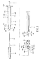
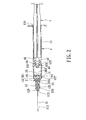
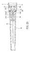
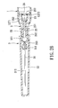
- the first preferred embodiment of a disposable syringe according to the present invention is shown to comprise a barrel 1, a tubular needle seat 2, a needle assembly 3 including a needle cannula 31 and a tip protector 32, and a plunger 4.
- the barrel 1 has a surrounding barrel wall 12 which surrounds an axis (X) in a longitudinal direction and which defines a passage 11 therein that has front and rear open ends 123, 124 opposite to each other.
- the surrounding barrel wall 12 has inner and outer wall surfaces 121, 122.
- the inner wall surface 121 includes a smaller-diameter front surface segment 126 and a larger-diameter rear surface segment 125 proximate to the front and rear open ends 123, 124, respectively, and an intermediate surface segment 127 disposed therebetween and converging from the rear surface segment 125 to the front surface segment 126.
- the intermediate surface segment 127 has a retaining region 14 which is axially distal from the front surface segment 126 and which extends radially and outwardly to form an annular recess 14.
- An annular shoulder abutment 13 is formed on the intermediate surface segment 127 rearwardly of the retaining region 14.
- the intermediate surface segment 127 defines first and second friction diminishing regions 1271, 1272 which are respectively interposed between the retaining region 14 and the front surface segment 126, and between the retaining region 14 and the rear surface segment 125 to be described in greater detail hereinafter.
- the outer wall surface 122 of the barrel 1 has a rib portion 129 extending in the longitudinal direction and disposed adjacent to the front open end 123.
- the tip protector 32 of the needle assembly 3 is disposed to sleeve on the outer wall surface 122 from the front open end 123, and is frictionally retained by the rib portion 129 for shielding the needle cannula 31.
- the needle seat 2 is insertable into the passage 11 from the rear open end 124 to surround the axis (X) .
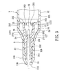
- the needle seat 2 includes a front engaging portion 22, a retaining portion 23, a rear engaging portion 25, a surrounding sealing flange 251, a plurality of radially yieldable catches 263, and a plurality of axially extending ribs 262.
- the front engaging portion 22 is configured to be in fluid-tight engagement with the front surface segment 126, and is disposed to fix the needle cannula 31 of the needle assembly 3 along the axis (X) .
- the front engaging portion 22 has a filling hole 292 filled with an adhesive to affix a secured segment 311 of the needle cannula 31 to the front engaging portion 22 (see Fig. 3) .
- the front surface segment 126 of the barrel 1 is configured to converge toward the front open end 123 to form a narrow opening 128 in the front open end 123 for passage of a sharp segment 312 of the needle cannula 31, thereby preventing removal of the needle seat 2 from the front open end 123.
- the retaining portion 23 is disposed rearwardly of the front engaging portion 22, and is retained at the retaining region 14 by virtue of a first frictional force when the needle seat 2 is in a position of use.
- the retaining portion 23 has a plurality of fins 272 which are angularly displaced from one another about the axis (X), and which are spaced apart from the first diminishing region 1271 radially so as to form a first movement space 273 therebetween.
- Each fin 272 is configured such that a contour constituted by the fins 272 about the axis (X) serves as a protrusion 28.
- the protrusion 28 is retained in the annular recess 14 by virtue of the first frictional force.
- the rear engaging portion 25 extends rearwardly from the retaining portion 23 to terminate at a rearwardly facing wall 212.
- the surrounding sealing flange 251 extends from the rearwardly facing wall 212 radially and outwardly to be in fluid-tight engagement with the rear surface segment 125, and extends forwardly to terminate at a surrounding flange surface 253.
- the surrounding flange surface 253 is spaced apart from the shoulder abutment 13 by the second friction diminishing region 1272 so as to forma second movement space 252 therebetween.
- the rear engaging portion 25 has an inner tubular wall surface 261 which surrounds the axis (X) to define a cavity 26 that extends from the rearwardly facing wall 212 towards the front engaging portion 22 and that terminates at a ceiling wall 24.
- the ceiling wall 24 has an axial hole 291 which is in fluid communication with the filling hole 292 to establish a fluid communication between the needle cannula 31 and the cavity 26.
- the radiallyyieldable catches 263 and the axially extending ribs 262 are formed on the inner tubular wall surface 261 distal from and proximate to the ceiling wall 24, respectively, and are angularly displaced from one another about the axis (X) .
- the radially yieldable catches 263 are yieldable radially and outwardly in response to a kinetic frictional force to be described in greater detail hereinafter.
- the plunger 4 is disposed to be movable in the passage 11 along the rear surface segment 125, and has a front end wall 41, an engaging head 43 which is opposite to the front end wall 41 in the longitudinal direction and which has a plurality of axially extending grooves 432, a neck 44 which is interposed between the engaging head 43 and the front end wall 41, and which is of a dimension such that a rearwardly facing shoulder wall 431 is formed between the engaging head 43 and the neck 44, and such that the aforesaid kinetic frictional force is generated as a result of axial movement of the engaging head 43 relative to the radially yieldable catches 263 towards the ceiling wall 24, and an axially extending stem 42 which is interposed between the neck 44 and the front end wall 41.
- a deformable sealing member 45 is sleeved on the engaging head 43 and the neck 44, is in frictional engagement with the engaging head 43 with a second frictional force, and is sealingly slidable relative to the rear surface segment 125. Furthermore, the deformable sealing member 45 is spaced apart from the front end wall 41 so as to permit relative movement of the deformable sealing member 45 towards the front end wall 41 when a pushing force is applied to the plunger 4 to overcome the second frictional force to be described in greater detail hereinafter.
- the deformable sealing member 45 is moved forward by virtue of forward movement of the plunger 4 to abut against the rearwardly facing wall 212, while the engaging head 43 extends into the cavity 26. The syringe is thus placed in an injection completed state.
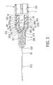
- the engaging head 43 is kept moving towards the ceiling wall 24 by a pushing force which is applied to the plunger 4, and which, when the deformable sealing member 45 is blocked by the rearwardly facing wall 212 from moving with the engaging head 43 and is moved rearwardly towards the front end wall 41, overcomes the second frictional force, thereby exposing the neck 44 to permit the rearwardly facing shoulder wall 431 to be forced to slip over the radiallyyieldable catches 263 and to be retained thereby such that the rearwardly facing shoulder wall 431 is prevented from moving rearwardly. Meanwhile, the axially extending grooves 432 are brought to mate with the axially extending ribs 262 so as to put the needle seat 2 into splined engagement with the engaging head 43.
- Fig. 7 shows the second preferred embodiment of a disposable syringe according to this invention.
- the disposable syringe of this embodiment further comprises an O-ring 5 which is sleeved tightlyon the front engaging portion 22 of the needle seat 2, and which surrounds the axis (X) so as to enhance fluid-tightness of the engagement between the front surface segment 126 and the front engaging portion 22.
- an O-ring 5 is disposed on the rear engaging portion 25 so as to enhance fluid-tightness of the engagement between the rear surface segment 125 and the surrounding sealing flange 251.
- the fourth preferred embodiment of a disposable syringe according to this invention is similar to the first preferred embodiment in construction.
- the differences reside in that the intermediate surface segment 127 has a plurality of fins 131 which are angularly displaced from one another about the axis (X) and which extend rearwardly to be spaced apart from the surrounding sealing flange 251 by the second friction diminishing region 1272.
- each of the fins 131 extends radially and inwardly to terminate at a distal end 1311.
- the distal ends 1311 of the fins 131 are configured such that a contour constituted by the distal ends 1311 about the axis (X) serves as the annular recess 14.
- the retaining portion 23 is formed with an annular protrusion 28 to be retained in the recess 14 by virtue of the first frictional force. Furthermore, a plurality of fins 272 are formed on the ceiling wall 24, and are angularly displaced from one another.
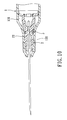
- Fig. 10 shows the fifth preferred embodiment of a disposable syringe according to this invention, which is substantially similar to the fourth preferred embodiment.
- an O-ring 5 is further sleeved tightly on the front engaging portion 22 of the needle seat 2, and is disposed to surround the axis (X) so as to enhance the fluid-tightness of the engagement between the front surface segment 126 and the front engaging portion 22.
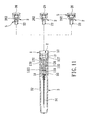
- the sixth preferred embodiment of a disposable syringe is shown to include a selected one of the needle seats 2 of the above embodiments.
- the outer wall surface 122 of the barrel 1 has an annular step portion 120 that faces forwardly, and that is distal from the front open end 123, and a surrounding front segment 1221 interposed between the front open end 123 and the annular step portion 120.
- the ribs 129 are formed rearwardly of the surrounding front segment 1221 so as to retainingly engage the tip protector 32.
- the disposable syringe further comprises a catheter hub 33 and a tubular catheter 34 for performing an intravenous catheter introducing process.
- the catheter hub 33 includes a surrounding hub wall whichhas a sleeve portion that is sleeved on the surrounding front segment 1221 and that has a terminal edge abutting against the step portion 120, and a tip portion opposite to the sleeve portion along the axis (X) .
- the tubular catheter 34 includes a proximate segment which is disposed in the tip portion and which extends along the axis (X), and a distal segment which extends from the proximate segment along the axis (X) to project outwardly of the tip portion.
- the barrel 1 is separated from the catheter hub 33 so as to complete the intravenous catheter introducing process.
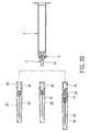
- the needle cannula 31 is then retracted into the barrel 1 in the same manner as described above, as shown in Fig. 12.
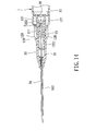
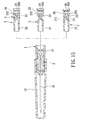
- the seventh preferred embodiment of a disposable syringe is shown to be similar to the sixth preferred embodiment in construction and function, except that the barrel 1 and the needle seat 2 are the same as those of the fourth and fifth preferred embodiments shown in Figs. 9 and 10. Furthermore, the front engaging portion 22 of the needle seat 2 is filled with an adhesive to affix a secured segment 311 of the needle cannula 31 to the front engagingportion 22.
- the disposable syringe of the eighth preferred embodiment is adapted for injecting medication of an extremely small volume, such as 1 ml. That is, the barrel 1 and the plunger 4 have relatively smaller diameters.
- the needle seat 2 may have an O-ring 5 or fins 272 disposed on the ceiling wall 24.
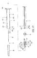
- the ninth preferred embodiment of a disposable syringe according to this invention is shown to be similar to the first preferred embodiment in construction.
- the differences therebetween are as follows.
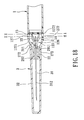
- the front engaging portion 22 of the needle seat 2 has a seat segment which is configured to extend outwardly of the barrel 1 from the front open end 123 when the needle seat 2 is in the position of use.
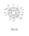
- the intermediate surface segment 127 has a plurality of barriers 15 which are angularly displaced from one another about the axis (X) so as to define a recessed access 151 between two adjacent ones of the barriers 15.
- the retaining region 14 has a plurality of recesses 141 which are angularly displaced from one another about the axis (X) and which are spaced apart from one another by protrusions 142, and a plurality of bumps 143 respectively extending from the recesses 141 inwardly and radially.
- the retaining portion 23 of the needle seat 2 has a plurality of partitions 272 in the form of fins 272 which are angularly displaced from one another about the axis (X), and a plurality of blocking segments 29 which respectively extend from the partitions 272 radially and outwardly.
- each of the partitions 272 is turned a predetermined angle in one of clockwise and counterclockwise directions such that each of the blocking segments 29 is received in and is engaged with a respective one of the recesses 141 by virtue of the first frictional force, as shown in Fig. 20, while being prevented by the corresponding barrier 15 from axial movement relative to the second diminishing region 1272, thereby placing the needle seat 2 firmly in the position of use.
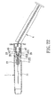
- the user can rotate the needle seat 2 so that the partitions 272 are turned the predetermined angle in a corresponding one of the counterclockwise and clockwise directions, as indicated by dotted lines in Fig. 21 so that the blocking segments 29 slip over the bumps 143, respectively (as indicated by solid lines in Fig. 21) .
- the user can be aware of the approaching of the blocking segments 29 to a position where the blocking segments 2 9 are unrestrained by the barriers 15 and are permitted to perform the axial movement. Therefore, the needle seat 2 is allowed to be pulled rearwardly so as to retract the needle cannula 31 into the passage 11, as shown in Fig. 22.
- the needle seat 2 has a plurality of fins 272 formed on the ceiling wall 24 and on the seat segment of the front engaging portion 22.
- the tipprotector 32 is disposed to sleeve on and is frictionally retained onto the seat segment of the front engaging portion 22 for shielding the sharp segment 312 of the needle cannula 31.
- the tenth preferred embodiment of a disposable syringe according to this invention is similar to the ninth preferred embodiment, and further comprises an O-ring 5 which is disposed on the front engaging portion 22 of the needle seat 2 so as to enhance fluid-tightness of the engagement between the front engaging portion 22 and the front surface segment 126 of the barrel 1.
- a catheter hub 33 and a tubular catheter 34 are further provided for performing an intravenous catheter introducing process.
- the catheter hub 33 includes a surrounding hub wall which has a sleeve portion that is sleeved on the seat segment of the front engaging portion 22, and a tip portion opposite to the sleeve portion along the axis (X).
- the tubular catheter 34 includes a proximate segment which is disposed in the tip portion and which extends along the axis (X), and a distal segment which extends from the proximate segment along the axis (X) and outwardly of the tip portion.
- the sleeve portion of the catheter hub 33 is sleeved on the seat segment of the front engaging portion 22, there is no need to form fins on the seat segment.
- the needle seat 2 further includes a hub segment 35 which is configured to fix the secured segment 311 of the needle cannula 31 along the axis (X), and which is sleeved on the seat segment of the front engaging portion 22 to establish fluid communication between the needle cannula 31 and the axial hole 291 through the filling hole 292 which is free fromadhesive .
- the hub segment 35 has a rib portion 353 formed on an outer surface 351 thereof so as to retain the tip protector 32 for shielding the sharp segment 312 of the needle cannula 31.
- the thirteenth preferred embodiment of a disposable syringe according to this invention is shown to be similar to the twelfth preferred embodiment in construction, and further comprises a catheter hub 33 and a tubular catheter 34 for performing an intravenous catheter introducing process. That is, the catheter hub 33 includes a surrounding hub wall which has a sleeve portion sleeved on the hub segment 35, and a tip portion opposite to the sleeve portion along the axis (X) .
- the tubular catheter 34 includes a proximate segment which is disposed in the tip portion and which extends along the axis (X), and a distal segment which extends from the proximate segment along the axis (X) and outwardly of the tip portion.
- the tip protector 32 is sleeved retainingly on the surrounding hub wall of the catheter hub 33.
- an O-ring 5 is additionally disposed on the front engaging portion 22 of the needle seat 2.
- any forms of the needle assembles 3, such as that including the catheter hub 33 and the tubular catheter 34 , that including the hub segment 35, and that including the catheter hub 33, the tubular catheter 34 and the hub segment 35, can be provided for use with the needle seat 2 as required.
Landscapes
- Health & Medical Sciences (AREA)
- Engineering & Computer Science (AREA)
- Heart & Thoracic Surgery (AREA)
- Vascular Medicine (AREA)
- Anesthesiology (AREA)
- Biomedical Technology (AREA)
- Environmental & Geological Engineering (AREA)
- Hematology (AREA)
- Life Sciences & Earth Sciences (AREA)
- Animal Behavior & Ethology (AREA)
- General Health & Medical Sciences (AREA)
- Public Health (AREA)
- Veterinary Medicine (AREA)
- Infusion, Injection, And Reservoir Apparatuses (AREA)
Priority Applications (4)
| Application Number | Priority Date | Filing Date | Title |
|---|---|---|---|
| AT04256241T ATE353684T1 (de) | 2004-10-08 | 2004-10-08 | Einwegspritze mit zurückziehbarer nadel |
| ES04256241T ES2282812T3 (es) | 2004-10-08 | 2004-10-08 | Jeringa desechable con una aguja retractable. |
| EP04256241A EP1645302B1 (de) | 2004-10-08 | 2004-10-08 | Einwegspritze mit zurückziehbarer Nadel |
| DE602004004789T DE602004004789T2 (de) | 2004-10-08 | 2004-10-08 | Einwegspritze mit zurückziehbarer Nadel |
Applications Claiming Priority (1)
| Application Number | Priority Date | Filing Date | Title |
|---|---|---|---|
| EP04256241A EP1645302B1 (de) | 2004-10-08 | 2004-10-08 | Einwegspritze mit zurückziehbarer Nadel |
Publications (2)
| Publication Number | Publication Date |
|---|---|
| EP1645302A1 true EP1645302A1 (de) | 2006-04-12 |
| EP1645302B1 EP1645302B1 (de) | 2007-02-14 |
Family
ID=34930725
Family Applications (1)
| Application Number | Title | Priority Date | Filing Date |
|---|---|---|---|
| EP04256241A Expired - Lifetime EP1645302B1 (de) | 2004-10-08 | 2004-10-08 | Einwegspritze mit zurückziehbarer Nadel |
Country Status (4)
| Country | Link |
|---|---|
| EP (1) | EP1645302B1 (de) |
| AT (1) | ATE353684T1 (de) |
| DE (1) | DE602004004789T2 (de) |
| ES (1) | ES2282812T3 (de) |
Cited By (3)
| Publication number | Priority date | Publication date | Assignee | Title |
|---|---|---|---|---|
| EP2489377A3 (de) * | 2011-02-17 | 2014-05-07 | Teleflex Medical Incorporated | Integrierte Spritzenvorrichtung mit Selbstabdeckungsverbinder |
| CN114126684A (zh) * | 2019-06-27 | 2022-03-01 | 夏普斯技术有限公司 | 用于低剂量注射的超低废物一次性安全注射器 |
| US12589211B2 (en) | 2021-01-29 | 2026-03-31 | Plasto Technology Group Llc | Needle and syringe system with automatic safety shield that renders a needle safe |
Citations (4)
| Publication number | Priority date | Publication date | Assignee | Title |
|---|---|---|---|---|
| US5318536A (en) * | 1989-07-11 | 1994-06-07 | Williams Graham H | Disposable hypodermic syringe with retractable needle |
| US5938641A (en) * | 1998-01-07 | 1999-08-17 | Villanueva; George | Safety syringe |
| EP0979660A1 (de) * | 1997-04-25 | 2000-02-16 | Yoshikuni Saito | Spritze |
| US20040153035A1 (en) * | 2002-11-22 | 2004-08-05 | Life-Shield Products Inc. | Retractable type safety syringe |
-
2004
- 2004-10-08 EP EP04256241A patent/EP1645302B1/de not_active Expired - Lifetime
- 2004-10-08 ES ES04256241T patent/ES2282812T3/es not_active Expired - Lifetime
- 2004-10-08 AT AT04256241T patent/ATE353684T1/de not_active IP Right Cessation
- 2004-10-08 DE DE602004004789T patent/DE602004004789T2/de not_active Expired - Lifetime
Patent Citations (4)
| Publication number | Priority date | Publication date | Assignee | Title |
|---|---|---|---|---|
| US5318536A (en) * | 1989-07-11 | 1994-06-07 | Williams Graham H | Disposable hypodermic syringe with retractable needle |
| EP0979660A1 (de) * | 1997-04-25 | 2000-02-16 | Yoshikuni Saito | Spritze |
| US5938641A (en) * | 1998-01-07 | 1999-08-17 | Villanueva; George | Safety syringe |
| US20040153035A1 (en) * | 2002-11-22 | 2004-08-05 | Life-Shield Products Inc. | Retractable type safety syringe |
Cited By (5)
| Publication number | Priority date | Publication date | Assignee | Title |
|---|---|---|---|---|
| EP2489377A3 (de) * | 2011-02-17 | 2014-05-07 | Teleflex Medical Incorporated | Integrierte Spritzenvorrichtung mit Selbstabdeckungsverbinder |
| CN114126684A (zh) * | 2019-06-27 | 2022-03-01 | 夏普斯技术有限公司 | 用于低剂量注射的超低废物一次性安全注射器 |
| KR20220031035A (ko) * | 2019-06-27 | 2022-03-11 | 샤프스 테크놀로지 아이엔씨. | 저용량 주입용 초-저 폐기물 일회용 주사기 |
| US11497860B2 (en) | 2019-06-27 | 2022-11-15 | Sharps Technology, Inc. | Ultra-low waste disposable safety syringe for low dose injections |
| US12589211B2 (en) | 2021-01-29 | 2026-03-31 | Plasto Technology Group Llc | Needle and syringe system with automatic safety shield that renders a needle safe |
Also Published As
| Publication number | Publication date |
|---|---|
| DE602004004789T2 (de) | 2007-11-22 |
| DE602004004789D1 (de) | 2007-03-29 |
| EP1645302B1 (de) | 2007-02-14 |
| ATE353684T1 (de) | 2007-03-15 |
| ES2282812T3 (es) | 2007-10-16 |
Similar Documents
| Publication | Publication Date | Title |
|---|---|---|
| US7303550B2 (en) | Disposable syringe with a retractable needle | |
| US6186980B1 (en) | Single-use device for injection | |
| JP4937139B2 (ja) | 医療用針のための安全装置 | |
| EP1558311B1 (de) | Sicherheitsnadel | |
| TWI639452B (zh) | 具有阻尼器的雙本體注射器載體總成 | |
| AU2015207514B2 (en) | Automatic injector | |
| ES2938565T3 (es) | Mecanismo de captura de cánula | |
| JP7235743B2 (ja) | 医療注射器用の注射器ホルダーおよび医療注射器アセンブリを形成する方法 | |
| JP5813500B2 (ja) | 径方向に移動可能な固定要素を持つ針保護アセンブリー | |
| CN102781500A (zh) | 具有设置在通道上以减小通道的有效孔径的突起的注射装置 | |
| US7066906B2 (en) | Disposable syringe | |
| EP1645302B1 (de) | Einwegspritze mit zurückziehbarer Nadel | |
| US6409703B1 (en) | Safety syringe for intravenous injection | |
| KR102695110B1 (ko) | 수축 가능한 주사기. | |
| KR102808763B1 (ko) | 다기능 바늘 홀더 및 리테이너 링 조립체를 가지는 주사기 | |
| US20080234635A1 (en) | Disposable syringe guarded in a preuse position (II) | |
| US20080167612A1 (en) | Intravenous catheter introducing device | |
| CA2429753C (en) | Disposable syringe | |
| CN118541183A (zh) | 具有可折叠柱塞的可缩回预填充注射器 | |
| EP1457221B1 (de) | Einwegspritze | |
| CA2408757C (en) | Disposable syringe | |
| EP1410816B1 (de) | Wegwerfspritze | |
| AU2003204251B2 (en) | Disposable syringe | |
| WO2003033061A1 (en) | Single-use syringe assembly | |
| MXPA96002214A (en) | Pu protection device |
Legal Events
| Date | Code | Title | Description |
|---|---|---|---|
| PUAI | Public reference made under article 153(3) epc to a published international application that has entered the european phase |
Free format text: ORIGINAL CODE: 0009012 |
|
| AK | Designated contracting states |
Kind code of ref document: A1 Designated state(s): AT BE BG CH CY CZ DE DK EE ES FI FR GB GR HU IE IT LI LU MC NL PL PT RO SE SI SK TR |
|
| AX | Request for extension of the european patent |
Extension state: AL HR LT LV MK |
|
| GRAP | Despatch of communication of intention to grant a patent |
Free format text: ORIGINAL CODE: EPIDOSNIGR1 |
|
| 17P | Request for examination filed |
Effective date: 20060418 |
|
| GRAS | Grant fee paid |
Free format text: ORIGINAL CODE: EPIDOSNIGR3 |
|
| RAP1 | Party data changed (applicant data changed or rights of an application transferred) |
Owner name: SHUE, PHILIP Owner name: SHUE, MING-JENG Owner name: HUANG, DEBORAH |
|
| RIN1 | Information on inventor provided before grant (corrected) |
Inventor name: SHUE, MING-JENG Inventor name: HUANG, DEBORAH Inventor name: SHUE, PHILIP |
|
| AKX | Designation fees paid |
Designated state(s): AT BE BG CH CY CZ DE DK EE ES FI FR GB GR HU IE IT LI LU MC NL PL PT RO SE SI SK TR |
|
| GRAA | (expected) grant |
Free format text: ORIGINAL CODE: 0009210 |
|
| AK | Designated contracting states |
Kind code of ref document: B1 Designated state(s): AT BE BG CH CY CZ DE DK EE ES FI FR GB GR HU IE IT LI LU MC NL PL PT RO SE SI SK TR |
|
| PG25 | Lapsed in a contracting state [announced via postgrant information from national office to epo] |
Ref country code: PL Free format text: LAPSE BECAUSE OF FAILURE TO SUBMIT A TRANSLATION OF THE DESCRIPTION OR TO PAY THE FEE WITHIN THE PRESCRIBED TIME-LIMIT Effective date: 20070214 Ref country code: NL Free format text: LAPSE BECAUSE OF FAILURE TO SUBMIT A TRANSLATION OF THE DESCRIPTION OR TO PAY THE FEE WITHIN THE PRESCRIBED TIME-LIMIT Effective date: 20070214 Ref country code: AT Free format text: LAPSE BECAUSE OF FAILURE TO SUBMIT A TRANSLATION OF THE DESCRIPTION OR TO PAY THE FEE WITHIN THE PRESCRIBED TIME-LIMIT Effective date: 20070214 Ref country code: SI Free format text: LAPSE BECAUSE OF FAILURE TO SUBMIT A TRANSLATION OF THE DESCRIPTION OR TO PAY THE FEE WITHIN THE PRESCRIBED TIME-LIMIT Effective date: 20070214 Ref country code: FI Free format text: LAPSE BECAUSE OF FAILURE TO SUBMIT A TRANSLATION OF THE DESCRIPTION OR TO PAY THE FEE WITHIN THE PRESCRIBED TIME-LIMIT Effective date: 20070214 Ref country code: LI Free format text: LAPSE BECAUSE OF FAILURE TO SUBMIT A TRANSLATION OF THE DESCRIPTION OR TO PAY THE FEE WITHIN THE PRESCRIBED TIME-LIMIT Effective date: 20070214 Ref country code: DK Free format text: LAPSE BECAUSE OF FAILURE TO SUBMIT A TRANSLATION OF THE DESCRIPTION OR TO PAY THE FEE WITHIN THE PRESCRIBED TIME-LIMIT Effective date: 20070214 Ref country code: CH Free format text: LAPSE BECAUSE OF FAILURE TO SUBMIT A TRANSLATION OF THE DESCRIPTION OR TO PAY THE FEE WITHIN THE PRESCRIBED TIME-LIMIT Effective date: 20070214 |
|
| REG | Reference to a national code |
Ref country code: GB Ref legal event code: FG4D |
|
| REG | Reference to a national code |
Ref country code: CH Ref legal event code: EP |
|
| REG | Reference to a national code |
Ref country code: GR Ref legal event code: EP Ref document number: 20070400583 Country of ref document: GR |
|
| REF | Corresponds to: |
Ref document number: 602004004789 Country of ref document: DE Date of ref document: 20070329 Kind code of ref document: P |
|
| REG | Reference to a national code |
Ref country code: RO Ref legal event code: EPE |
|
| REG | Reference to a national code |
Ref country code: IE Ref legal event code: FG4D |
|
| REG | Reference to a national code |
Ref country code: SE Ref legal event code: TRGR |
|
| PG25 | Lapsed in a contracting state [announced via postgrant information from national office to epo] |
Ref country code: BG Free format text: LAPSE BECAUSE OF FAILURE TO SUBMIT A TRANSLATION OF THE DESCRIPTION OR TO PAY THE FEE WITHIN THE PRESCRIBED TIME-LIMIT Effective date: 20070515 |
|
| PG25 | Lapsed in a contracting state [announced via postgrant information from national office to epo] |
Ref country code: PT Free format text: LAPSE BECAUSE OF FAILURE TO SUBMIT A TRANSLATION OF THE DESCRIPTION OR TO PAY THE FEE WITHIN THE PRESCRIBED TIME-LIMIT Effective date: 20070716 |
|
| NLV1 | Nl: lapsed or annulled due to failure to fulfill the requirements of art. 29p and 29m of the patents act | ||
| ET | Fr: translation filed | ||
| REG | Reference to a national code |
Ref country code: CH Ref legal event code: PL |
|
| REG | Reference to a national code |
Ref country code: ES Ref legal event code: FG2A Ref document number: 2282812 Country of ref document: ES Kind code of ref document: T3 |
|
| PG25 | Lapsed in a contracting state [announced via postgrant information from national office to epo] |
Ref country code: SK Free format text: LAPSE BECAUSE OF FAILURE TO SUBMIT A TRANSLATION OF THE DESCRIPTION OR TO PAY THE FEE WITHIN THE PRESCRIBED TIME-LIMIT Effective date: 20070214 |
|
| PLBE | No opposition filed within time limit |
Free format text: ORIGINAL CODE: 0009261 |
|
| STAA | Information on the status of an ep patent application or granted ep patent |
Free format text: STATUS: NO OPPOSITION FILED WITHIN TIME LIMIT |
|
| PG25 | Lapsed in a contracting state [announced via postgrant information from national office to epo] |
Ref country code: CZ Free format text: LAPSE BECAUSE OF FAILURE TO SUBMIT A TRANSLATION OF THE DESCRIPTION OR TO PAY THE FEE WITHIN THE PRESCRIBED TIME-LIMIT Effective date: 20070214 |
|
| 26N | No opposition filed |
Effective date: 20071115 |
|
| PG25 | Lapsed in a contracting state [announced via postgrant information from national office to epo] |
Ref country code: IE Free format text: LAPSE BECAUSE OF NON-PAYMENT OF DUE FEES Effective date: 20071008 |
|
| PGFP | Annual fee paid to national office [announced via postgrant information from national office to epo] |
Ref country code: RO Payment date: 20080912 Year of fee payment: 5 |
|
| PG25 | Lapsed in a contracting state [announced via postgrant information from national office to epo] |
Ref country code: EE Free format text: LAPSE BECAUSE OF FAILURE TO SUBMIT A TRANSLATION OF THE DESCRIPTION OR TO PAY THE FEE WITHIN THE PRESCRIBED TIME-LIMIT Effective date: 20070214 |
|
| PGFP | Annual fee paid to national office [announced via postgrant information from national office to epo] |
Ref country code: MC Payment date: 20081002 Year of fee payment: 5 |
|
| PGFP | Annual fee paid to national office [announced via postgrant information from national office to epo] |
Ref country code: ES Payment date: 20081121 Year of fee payment: 5 |
|
| PGFP | Annual fee paid to national office [announced via postgrant information from national office to epo] |
Ref country code: IT Payment date: 20081025 Year of fee payment: 5 Ref country code: SE Payment date: 20081022 Year of fee payment: 5 Ref country code: BE Payment date: 20081009 Year of fee payment: 5 |
|
| PGFP | Annual fee paid to national office [announced via postgrant information from national office to epo] |
Ref country code: FR Payment date: 20081014 Year of fee payment: 5 |
|
| PGFP | Annual fee paid to national office [announced via postgrant information from national office to epo] |
Ref country code: GR Payment date: 20081002 Year of fee payment: 5 |
|
| PG25 | Lapsed in a contracting state [announced via postgrant information from national office to epo] |
Ref country code: CY Free format text: LAPSE BECAUSE OF FAILURE TO SUBMIT A TRANSLATION OF THE DESCRIPTION OR TO PAY THE FEE WITHIN THE PRESCRIBED TIME-LIMIT Effective date: 20070214 |
|
| PG25 | Lapsed in a contracting state [announced via postgrant information from national office to epo] |
Ref country code: LU Free format text: LAPSE BECAUSE OF NON-PAYMENT OF DUE FEES Effective date: 20071008 |
|
| PG25 | Lapsed in a contracting state [announced via postgrant information from national office to epo] |
Ref country code: HU Free format text: LAPSE BECAUSE OF FAILURE TO SUBMIT A TRANSLATION OF THE DESCRIPTION OR TO PAY THE FEE WITHIN THE PRESCRIBED TIME-LIMIT Effective date: 20070815 |
|
| BERE | Be: lapsed |
Owner name: SHUE, MING-JENG Effective date: 20091031 Owner name: HUANG, DEBORAH Effective date: 20091031 Owner name: SHUE, PHILIP Effective date: 20091031 |
|
| PG25 | Lapsed in a contracting state [announced via postgrant information from national office to epo] |
Ref country code: MC Free format text: LAPSE BECAUSE OF NON-PAYMENT OF DUE FEES Effective date: 20091031 |
|
| EUG | Se: european patent has lapsed | ||
| REG | Reference to a national code |
Ref country code: FR Ref legal event code: ST Effective date: 20100630 |
|
| PG25 | Lapsed in a contracting state [announced via postgrant information from national office to epo] |
Ref country code: FR Free format text: LAPSE BECAUSE OF NON-PAYMENT OF DUE FEES Effective date: 20091102 |
|
| PG25 | Lapsed in a contracting state [announced via postgrant information from national office to epo] |
Ref country code: GR Free format text: LAPSE BECAUSE OF NON-PAYMENT OF DUE FEES Effective date: 20100504 Ref country code: BE Free format text: LAPSE BECAUSE OF NON-PAYMENT OF DUE FEES Effective date: 20091031 |
|
| PG25 | Lapsed in a contracting state [announced via postgrant information from national office to epo] |
Ref country code: RO Free format text: LAPSE BECAUSE OF NON-PAYMENT OF DUE FEES Effective date: 20091008 |
|
| REG | Reference to a national code |
Ref country code: ES Ref legal event code: FD2A Effective date: 20110307 |
|
| PG25 | Lapsed in a contracting state [announced via postgrant information from national office to epo] |
Ref country code: IT Free format text: LAPSE BECAUSE OF NON-PAYMENT OF DUE FEES Effective date: 20091008 |
|
| PG25 | Lapsed in a contracting state [announced via postgrant information from national office to epo] |
Ref country code: SE Free format text: LAPSE BECAUSE OF NON-PAYMENT OF DUE FEES Effective date: 20091009 |
|
| PG25 | Lapsed in a contracting state [announced via postgrant information from national office to epo] |
Ref country code: ES Free format text: LAPSE BECAUSE OF NON-PAYMENT OF DUE FEES Effective date: 20110304 |
|
| PG25 | Lapsed in a contracting state [announced via postgrant information from national office to epo] |
Ref country code: ES Free format text: LAPSE BECAUSE OF NON-PAYMENT OF DUE FEES Effective date: 20091009 |
|
| PGFP | Annual fee paid to national office [announced via postgrant information from national office to epo] |
Ref country code: TR Payment date: 20080918 Year of fee payment: 5 |
|
| PG25 | Lapsed in a contracting state [announced via postgrant information from national office to epo] |
Ref country code: TR Free format text: LAPSE BECAUSE OF NON-PAYMENT OF DUE FEES Effective date: 20091008 |
|
| PGFP | Annual fee paid to national office [announced via postgrant information from national office to epo] |
Ref country code: GB Payment date: 20180921 Year of fee payment: 15 |
|
| PGFP | Annual fee paid to national office [announced via postgrant information from national office to epo] |
Ref country code: DE Payment date: 20180925 Year of fee payment: 15 |
|
| REG | Reference to a national code |
Ref country code: DE Ref legal event code: R119 Ref document number: 602004004789 Country of ref document: DE |
|
| PG25 | Lapsed in a contracting state [announced via postgrant information from national office to epo] |
Ref country code: DE Free format text: LAPSE BECAUSE OF NON-PAYMENT OF DUE FEES Effective date: 20200501 |
|
| GBPC | Gb: european patent ceased through non-payment of renewal fee |
Effective date: 20191008 |
|
| PG25 | Lapsed in a contracting state [announced via postgrant information from national office to epo] |
Ref country code: GB Free format text: LAPSE BECAUSE OF NON-PAYMENT OF DUE FEES Effective date: 20191008 |