EP1645302B1 - Einwegspritze mit zurückziehbarer Nadel - Google Patents
Einwegspritze mit zurückziehbarer Nadel Download PDFInfo
- Publication number
- EP1645302B1 EP1645302B1 EP04256241A EP04256241A EP1645302B1 EP 1645302 B1 EP1645302 B1 EP 1645302B1 EP 04256241 A EP04256241 A EP 04256241A EP 04256241 A EP04256241 A EP 04256241A EP 1645302 B1 EP1645302 B1 EP 1645302B1
- Authority
- EP
- European Patent Office
- Prior art keywords
- wall
- segment
- disposable syringe
- axis
- needle seat
- Prior art date
- Legal status (The legal status is an assumption and is not a legal conclusion. Google has not performed a legal analysis and makes no representation as to the accuracy of the status listed.)
- Expired - Lifetime
Links
Images









Classifications
-
- A—HUMAN NECESSITIES
- A61—MEDICAL OR VETERINARY SCIENCE; HYGIENE
- A61M—DEVICES FOR INTRODUCING MEDIA INTO, OR ONTO, THE BODY; DEVICES FOR TRANSDUCING BODY MEDIA OR FOR TAKING MEDIA FROM THE BODY; DEVICES FOR PRODUCING OR ENDING SLEEP OR STUPOR
- A61M5/00—Devices for bringing media into the body in a subcutaneous, intra-vascular or intramuscular way; Accessories therefor, e.g. filling or cleaning devices, arm-rests
- A61M5/178—Syringes
- A61M5/31—Details
- A61M5/32—Needles; Details of needles pertaining to their connection with syringe or hub; Accessories for bringing the needle into, or holding the needle on, the body; Devices for protection of needles
- A61M5/3205—Apparatus for removing or disposing of used needles or syringes, e.g. containers; Means for protection against accidental injuries from used needles
- A61M5/321—Means for protection against accidental injuries by used needles
- A61M5/322—Retractable needles, i.e. disconnected from and withdrawn into the syringe barrel by the piston
-
- A—HUMAN NECESSITIES
- A61—MEDICAL OR VETERINARY SCIENCE; HYGIENE
- A61M—DEVICES FOR INTRODUCING MEDIA INTO, OR ONTO, THE BODY; DEVICES FOR TRANSDUCING BODY MEDIA OR FOR TAKING MEDIA FROM THE BODY; DEVICES FOR PRODUCING OR ENDING SLEEP OR STUPOR
- A61M25/00—Catheters; Hollow probes
- A61M25/01—Introducing, guiding, advancing, emplacing or holding catheters
- A61M25/06—Body-piercing guide needles or the like
- A61M25/0612—Devices for protecting the needle; Devices to help insertion of the needle, e.g. wings or holders
-
- A—HUMAN NECESSITIES
- A61—MEDICAL OR VETERINARY SCIENCE; HYGIENE
- A61M—DEVICES FOR INTRODUCING MEDIA INTO, OR ONTO, THE BODY; DEVICES FOR TRANSDUCING BODY MEDIA OR FOR TAKING MEDIA FROM THE BODY; DEVICES FOR PRODUCING OR ENDING SLEEP OR STUPOR
- A61M25/00—Catheters; Hollow probes
- A61M25/01—Introducing, guiding, advancing, emplacing or holding catheters
- A61M25/06—Body-piercing guide needles or the like
- A61M25/0612—Devices for protecting the needle; Devices to help insertion of the needle, e.g. wings or holders
- A61M25/0631—Devices for protecting the needle; Devices to help insertion of the needle, e.g. wings or holders having means for fully covering the needle after its withdrawal, e.g. needle being withdrawn inside the handle or a cover being advanced over the needle
-
- A—HUMAN NECESSITIES
- A61—MEDICAL OR VETERINARY SCIENCE; HYGIENE
- A61M—DEVICES FOR INTRODUCING MEDIA INTO, OR ONTO, THE BODY; DEVICES FOR TRANSDUCING BODY MEDIA OR FOR TAKING MEDIA FROM THE BODY; DEVICES FOR PRODUCING OR ENDING SLEEP OR STUPOR
- A61M5/00—Devices for bringing media into the body in a subcutaneous, intra-vascular or intramuscular way; Accessories therefor, e.g. filling or cleaning devices, arm-rests
- A61M5/178—Syringes
- A61M5/31—Details
- A61M5/315—Pistons; Piston-rods; Guiding, blocking or restricting the movement of the rod or piston; Appliances on the rod for facilitating dosing ; Dosing mechanisms
- A61M5/31511—Piston or piston-rod constructions, e.g. connection of piston with piston-rod
- A61M5/31515—Connection of piston with piston rod
Definitions
- This invention relates to a disposable syringe, more particularly to a disposable syringe with a friction diminishing means to facilitate retraction of a needle into a barrel for safe disposal.
- the object of the present invention is to provide a disposable syringe which permits steady and successful retraction of a needle, and which can reduce failure in production.
- the disposable syringe includes a barrel, a tubular needle seat and a plunger.
- the barrel has an axially extending surrounding barrel wall which defines a passage with front and rear open ends.
- An inner wall surface of the surrounding barrel wall includes front and rear surface segments and an intermediate surface segment disposed therebetween.
- the intermediate surface segment has a retaining region axially distal from the front surface segment, and first and second friction diminishing regions respectively interposed between the retaining region and the front surface segment, and between the retaining region and the rear surface segment.
- the tubular needle seat is insertable into the passage from the rear open end, and includes a front engaging portion in fluid-tight engagement with the front surface segment to fix a needle cannula, a retaining portion which is disposed rearwardly of the front engaging portion, and which is retained at the retaining region by virtue of a first frictional force when the needle seat is in a position of use, a rear engaging portion which extends rearwardly from the retaining portion to terminate at a rearwardly facing wall, and a surrounding sealing flange which extends from the rearwardly facing wall radially and outwardly to be in fluid-tight engagement with the rear surface segment, and which extends forwardly to terminate at a surrounding flange surface that is movable towards the second friction diminishing region.
- the rear engaging portion has an inner tubular wall surface defining a cavity which extends from the rearwardly facing wall to terminate at a ceiling wall.
- the ceiling wall has an axial hole which establishes a fluid communication between the needle cannula and the cavity.
- a radially yieldable catch is disposed on the inner tubular wall surface distal from the ceiling wall, and is yieldable radially and outwardly in response to a kinetic frictional force.
- the plunger is movable in the passage, and has a front end wall, an engaging head opposite to the front end wall, and a neck interposed therebetween and of a dimension such that a rearwardly facing shoulder wall is formed between the engaging head and the neck.
- the kinetic frictional force is generated as a result of axial movement of the engaging head relative to the radially yieldable catch towards the ceiling wall.
- a deformable sealing member is sleeved on the engaging head and the neck, is in frictional engagement with the engaging head with a second frictional force, and is sealingly slidable relative to the rear surface segment.
- the deformable sealing member In the position of use, the deformable sealing member is moved forward by virtue of forward movement of the plunger to abut against the rearwardly facing wall, while the engaging head is extended into the cavity.
- the engaging head When the plunger is to be placed in a disposal position, the engaging head is kept moving towards the ceiling wall by a pushing force which is applied to the plunger, and which, when the deformable sealing member is blocked by the rearwardly facing wall from moving with the engaging head, overcomes the second frictional force, thereby exposing the neck so as to permit the rearwardly facing shoulder wall to be forced to slip over the radially yieldable catch and to be prevented from moving rearwardly by the radially yieldable catch.
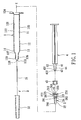
- the first preferred embodiment of a disposable syringe according to the present invention is shown to comprise a barrel 1, a tubular needle seat 2, a needle assembly 3 including a needle cannula 31 and a tip protector 32, and a plunger 4.
- the barrel 1 has a surrounding barrel wall 12 which surrounds an axis (X) in a longitudinal direction and which defines a passage 11 therein that has front and rear open ends 123, 124 opposite to each other.
- the surrounding barrel wall 12 has inner and outer wall surfaces 121, 122.
- the inner wall surface 121 includes a smaller-diameter front surface segment 126 and a larger-diameter rear surface segment 125 proximate to the front and rear open ends 123, 124, respectively, and an intermediate surface segment 127 disposed therebetween and converging from the rear surface segment 125 to the front surface segment 126.
- the intermediate surface segment 127 has a retaining region 14 which is axially rearwardly disposed from the front surface segment 126 and which extends radially and outwardly to form an annular recess 14.
- An annular shoulder abutment 13 is formed on the intermediate surface segment 127 rearwardly of the retaining region 14.
- the intermediate surface segment 127 defines first and second friction diminishing regions 1271, 1272 which are respectively interposed between the retaining region 14 and the front surface segment 126, and between the retaining region 14 and the rear surface segment 125 to be described in greater detail hereinafter.
- the outer wall surface 122 of the barrel 1 has a rib portion 129 extending in the longitudinal direction and disposed adjacent to the front open end 123.
- the tip protector 32 of the needle assembly 3 is disposed to sleeve on the outer wall surface 122 from the front open end 123, and is frictionally retained by the rib portion 129 for shielding the needle cannula 31.
- the needle seat 2 is insertable into the passage 11 from the rear open end 124 to surround the axis (X) .
- the needle seat 2 includes a front engaging portion 22, a retaining portion 23, a rear engaging portion 25, a surrounding sealing flange 251, a plurality of radially yieldable catches 263, and a plurality of axially extending ribs 262.
- the front engaging portion 22 is configured to be in fluid-tight engagement with the front surface segment 126, and is disposed to fix the needle cannula 31 of the needle assembly 3 along the axis (X) .
- the front engaging portion 22 has a filling hole 292 filled with an adhesive to affix a secured segment 311 of the needle cannula 31 to the front engaging portion 22 (see Fig. 3) .
- the front surface segment 126 of the barrel 1 is configured to converge toward the front open end 123 to form a narrow opening 128 in the front open end 123 for passage of a sharp segment 312 of the needle cannula 31, thereby preventing removal of the needle seat 2 from the front open end 123.
- the retaining portion 23 is disposed rearwardly of the front engaging portion 22, and is retained at the retaining region 14 by virtue of a first frictional force when the needle seat 2 is in a position of use.
- the retaining portion 23 has a plurality of fins 272 which are angularly displaced from one another about the axis (X), and which are spaced apart from the first friction diminishing region 1271 radially so as to form a first movement space 273 therebetween.
- Each fin 272 is configured such that a contour constituted by the fins 272 about the axis (X) serves as a protrusion 28.
- the protrusion 28 is retained in the annular recess 14 by virtue of the first frictional force.
- the rear engaging portion 25 extends rearwardly from the retaining portion 23 to terminate at a rearwardly facing wall 212.
- the surrounding sealing flange 251 extends from the rearwardly facing wall 212 radially and outwardly to be in fluid-tight engagement with the rear surface segment 125, and extends forwardly to terminate at a surrounding flange surface 253.
- the surrounding flange surface 253 is spaced apart from the shoulder abutment 13 by the second friction diminishing region 1272 so as to forma second movement space 252 therebetween.
- the rear engaging portion 25 has an inner tubular wall surface 261 which surrounds the axis (X) to define a cavity 26 that extends from the rearwardly facing wall 212 towards the front engaging portion 22 and that terminates at a ceiling wall 24.
- the ceiling wall 24 has an axial hole 291 which is in fluid communication with the filling hole 292 to establish a fluid communication between the needle cannula 31 and the cavity 26.
- the radiallyyieldable catches 263 and the axially extending ribs 262 are formed on the inner tubular wall surface 261 distal from and proximate to the ceiling wall 24, respectively, and are angularly displaced from one another about the axis (X) .
- the radially yieldable catches 263 are yieldable radially and outwardly in response to a kinetic frictional force to be described in greater detail hereinafter.
- the plunger 4 is disposed to be movable in the passage 11 along the rear surface segment 125, and has a front end wall 41, an engaging head 43 which is opposite to the front end wall 41 in the longitudinal direction and which has a plurality of axially extending grooves 432, a neck 44 which is interposed between the engaging head 43 and the front end wall 41, and which is of a dimension such that a rearwardly facing shoulder wall 431 is formed between the engaging head 43 and the neck 44, and such that the aforesaid kinetic frictional force is generated as a result of axial movement of the engaging head 43 relative to the radially yieldable catches 263 towards the ceiling wall 24, and an axially extending stem 42 which is interposed between the neck 44 and the front end wall 41.
- a deformable sealing member 45 is sleeved on the engaging head 43 and the neck 44, is in frictional engagement with the engaging head 43 with a second frictional force, and is sealingly slidable relative to the rear surface segment 125. Furthermore, the deformable sealing member 45 is spaced apart from the front end wall 41 so as to permit relative movement of the deformable sealing member 45 towards the front end wall 41 when a pushing force is applied to the plunger 4 to overcome the second frictional force to be described in greater detail hereinafter.
- the deformable sealing member 45 is moved forward by virtue of forward movement of the plunger 4 to abut against the rearwardly facing wall 212, while the engaging head 43 extends into the cavity 26. The syringe is thus placed in an injection completed state.
- the engaging head 43 is kept moving towards the ceiling wall 24 by a pushing force which is applied to the plunger 4, and which, when the deformable sealing member 45 is blocked by the rearwardly facing wall 212 from moving with the engaging head 43 and is moved rearwardly towards the front end wall 41, overcomes the second frictional force, thereby exposing the neck 44 to permit the rearwardly facing shoulder wall 431 to be forced to slip over the radiallyyieldable catches 263 and to be retained thereby such that the rearwardly facing shoulder wall 431 is prevented from moving rearwardly. Meanwhile, the axially extending grooves 432 are brought to mate with the axially extending ribs 262 so as to put the needle seat 2 into splined engagement with the engaging head 43.
- Fig. 7 shows the second preferred embodiment of a disposable syringe according to this invention.
- the disposable syringe of this embodiment further comprises an O-ring 5 which is sleeved tightlyon the front engaging portion 22 of the needle seat 2, and which surrounds the axis (X) so as to enhance fluid-tightness of the engagement between the front surface segment 126 and the front engaging portion 22.
- an O-ring 5 is disposed on the rear engaging portion 25 so as to enhance fluid-tightness of the engagement between the rear surface segment 125 and the surrounding sealing flange 251.
- the fourth preferred embodiment of a disposable syringe according to this invention is similar to the first preferred embodiment in construction.
- the differences reside in that the intermediate surface segment 127 has a plurality of fins 131 which are angularly displaced from one another about the axis (X) and which extend rearwardly to be spaced apart from the surrounding sealing flange 251 by the second friction diminishing region 1272.
- each of the fins 131 extends radially and inwardly to terminate at a distal end 1311.
- the distal ends 1311 of the fins 131 are configured such that a contour constituted by the distal ends 1311 about the axis (X) serves as the annular recess 14.
- the retaining portion 23 is formed with an annular protrusion 28 to be retained in the recess 14 by virtue of the first frictional force. Furthermore, a plurality of fins 272 are formed on the ceiling wall 24, and are angularly displaced from one another.
- Fig. 10 shows the fifth preferred embodiment of a disposable syringe according to this invention, which is substantially similar to the fourth preferred embodiment.
- an O-ring 5 is further sleeved tightly on the front engaging portion 22 of the needle seat 2, and is disposed to surround the axis (X) so as to enhance the fluid-tightness of the engagement between the front surface segment 126 and the front engaging portion 22.
- the sixth preferred embodiment of a disposable syringe is shown to include a selected one of the needle seats 2 of the above embodiments.
- the outer wall surface 122 of the barrel 1 has an annular step portion 120 that faces forwardly, and that is distal from the front open end 123, and a surrounding front segment 1221 interposed between the front open end 123 and the annular step portion 120.
- the ribs 129 are formed rearwardly of the surrounding front segment 1221 so as to retainingly engage the tip protector 32.
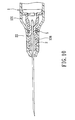
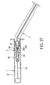
- the disposable syringe further comprises a catheter hub 33 and a tubular catheter 34 for performing an intravenous catheter introducing process.
- the catheter hub 33 includes a surrounding hub wall whichhas a sleeve portion that is sleeved on the surrounding front segment 1221 and that has a terminal edge abutting against the step portion 120, and a tip portion opposite to the sleeve portion along the axis (X) .
- the tubular catheter 34 includes a proximate segment which is disposed in the tip portion and which extends along the axis (X), and a distal segment which extends from the proximate segment along the axis (X) to project outwardly of the tip portion.
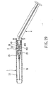
- the barrel 1 is separated from the catheter hub 33 so as to complete the intravenous catheter introducing process.
- the needle cannula 31 is then retracted into the barrel 1 in the same manner as described above, as shown in Fig. 12.
- the seventh preferred embodiment of a disposable syringe is shown to be similar to the sixth preferred embodiment in construction and function, except that the barrel 1 and the needle seat 2 are the same as those of the fourth and fifth preferred embodiments shown in Figs. 9 and 10. Furthermore, the front engaging portion 22 of the needle seat 2 is filled with an adhesive to affix a secured segment 311 of the needle cannula 31 to the front engagingportion 22.
- the disposable syringe of the eighth preferred embodiment is adapted for injecting medication of an extremely small volume, such as 1 ml. That is, the barrel 1 and the plunger 4 have relatively smaller diameters.
- the needle seat 2 may have an O-ring 5 or fins 272 disposed on the ceiling wall 24.
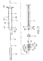
- the ninth preferred embodiment of a disposable syringe according to this invention is shown to be similar to the first preferred embodiment in construction.
- the differences therebetween are as follows.
- the front engaging portion 22 of the needle seat 2 has a seat segment which is configured to extend outwardly of the barrel 1 from the front open end 123 when the needle seat 2 is in the position of use.
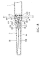
- the intermediate surface segment 127 has a plurality of barriers 15 which are angularly displaced from one another about the axis (X) so as to define a recessed access 151 between two adjacent ones of the barriers 15.
- the retaining region 14 has a plurality of recesses 141 which are angularly displaced from one another about the axis (X) and which are spaced apart from one another by protrusions 142, and a plurality of bumps 143 respectively extending from the recesses 141 inwardly and radially.
- the retaining portion 23 of the needle seat 2 has a plurality of partitions 272 in the form of fins 272 which are angularly displaced from one another about the axis (X), and a plurality of blocking segments 29 which respectively extend from the partitions 272 radially and outwardly.
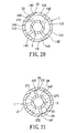
- each of the partitions 272 is turned a predetermined angle in one of clockwise and counterclockwise directions such that each of the blocking segments 29 is received in and is engaged with a respective one of the recesses 141 by virtue of the first frictional force, as shown in Fig. 20, while being prevented by the corresponding barrier 15 from axial movement relative to the second diminishing region 1272, thereby placing the needle seat 2 firmly in the position of use.
- the user can rotate the needle seat 2 so that the partitions 272 are turned the predetermined angle in a corresponding one of the counterclockwise and clockwise directions, as indicated by dotted lines in Fig. 21 so that the blocking segments 29 slip over the bumps 143, respectively (as indicated by solid lines in Fig. 21) .
- the user can be aware of the approaching of the blocking segments 29 to a position where the blocking segments 2 9 are unrestrained by the barriers 15 and are permitted to perform the axial movement. Therefore, the needle seat 2 is allowed to be pulled rearwardly so as to retract the needle cannula 31 into the passage 11, as shown in Fig. 22.
- the needle seat 2 has a plurality of fins 272 formed on the ceiling wall 24 and on the seat segment of the front engaging portion 22.
- the tipprotector 32 is disposed to sleeve on and is frictionally retained onto the seat segment of the front engaging portion 22 for shielding the sharp segment 312 of the needle cannula 31.
- the tenth preferred embodiment of a disposable syringe according to this invention is similar to the ninth preferred embodiment, and further comprises an O-ring 5 which is disposed on the front engaging portion 22 of the needle seat 2 so as to enhance fluid-tightness of the engagement between the front engaging portion 22 and the front surface segment 126 of the barrel 1.
- a catheter hub 33 and a tubular catheter 34 are further provided for performing an intravenous catheter introducing process.
- the catheter hub 33 includes a surrounding hub wall which has a sleeve portion that is sleeved on the seat segment of the front engaging portion 22, and a tip portion opposite to the sleeve portion along the axis (X).
- the tubular catheter 34 includes a proximate segment which is disposed in the tip portion and which extends along the axis (X), and a distal segment which extends from the proximate segment along the axis (X) and outwardly of the tip portion.
- the sleeve portion of the catheter hub 33 is sleeved on the seat segment of the front engaging portion 22, there is no need to form fins on the seat segment.
- the needle seat 2 further includes a hub segment 35 which is configured to fix the secured segment 311 of the needle cannula 31 along the axis (X), and which is sleeved on the seat segment of the front engaging portion 22 to establish fluid communication between the needle cannula 31 and the axial hole 291 through the filling hole 292 which is free fromadhesive .
- the hub segment 35 has a rib portion 353 formed on an outer surface 351 thereof so as to retain the tip protector 32 for shielding the sharp segment 312 of the needle cannula 31.
- the thirteenth preferred embodiment of a disposable syringe according to this invention is shown to be similar to the twelfth preferred embodiment in construction, and further comprises a catheter hub 33 and a tubular catheter 34 for performing an intravenous catheter introducing process. That is, the catheter hub 33 includes a surrounding hub wall which has a sleeve portion sleeved on the hub segment 35, and a tip portion opposite to the sleeve portion along the axis (X) .
- the tubular catheter 34 includes a proximate segment which is disposed in the tip portion and which extends along the axis (X), and a distal segment which extends from the proximate segment along the axis (X) and outwardly of the tip portion.
- the tip protector 32 is sleeved retainingly on the surrounding hub wall of the catheter hub 33.
- an O-ring 5 is additionally disposed on the front engaging portion 22 of the needle seat 2.
- any forms of the needle assembles 3, such as that including the catheter hub 33 and the tubular catheter 34 , that including the hub segment 35, and that including the catheter hub 33, the tubular catheter 34 and the hub segment 35, can be provided for use with the needle seat 2 as required.
Landscapes
- Health & Medical Sciences (AREA)
- Engineering & Computer Science (AREA)
- Heart & Thoracic Surgery (AREA)
- Vascular Medicine (AREA)
- Anesthesiology (AREA)
- Biomedical Technology (AREA)
- Environmental & Geological Engineering (AREA)
- Hematology (AREA)
- Life Sciences & Earth Sciences (AREA)
- Animal Behavior & Ethology (AREA)
- General Health & Medical Sciences (AREA)
- Public Health (AREA)
- Veterinary Medicine (AREA)
- Infusion, Injection, And Reservoir Apparatuses (AREA)
Claims (19)
- Einwegspritze, die Folgendes umfasst:einen Zylinder (1) mit einer umrandenden Zylinderwand (12), die eine Achse (X) in einer Längsrichtung umgibt und die einen Durchgang (11) darin definiert, der ein vorderes undein hinteres offenes Ende (123, 124) hat, die einander entgegengesetzt sind, wobei die umrandende Zylinderwand (12) eine Innenwandfläche (121) hat, die vordere und hintere Oberflächensegmente (126, 125) nahe dem vorderen bzw. hinteren offenen Ende (123, 124) und ein dazwischen angeordnetes Oberflächenzwischensegment (127) aufweist,eine Hohlnadel (31);einen röhrenförmigen Nadelsitz (2), der von dem hinteren offenen Ende (124) herin den Durchgang (11) einsetzbar konfiguriert ist und die Achse (X) umgibt; undeinen Kolben (4), der in dem Durchgang (11) entlang dem hinteren Oberflächensegment (125) bewegbar angeordnet ist; wobei:das Oberflächenzwischensegment (127) des Zylinders (1) eine Halteregion (14), die axial rückwärts von dem vorderen Oberflächensegment (126) angeordnet ist, und eine erste und eine zweite Reibungsminderungsregion (1271, 1272) hat, die zwischen der Halteregion (14) und dem vorderen Oberflächensegment (126) bzw. zwischen der Halteregion (14) und dem hinteren Oberflächensegment (125) angeordnet sind;der Nadelsitz (2) Folgendes aufweist:einen vorderen Eingriffsabschnitt (22), der für fluiddichten Eingriff mit dem vorderen Oberflächensegment (126) konfiguriert ist und zum Befestigen der Hohlnadel (31) entlang der Achse (X) angeordnet ist,einen Halteabschnitt (23), der rückwärts von dem vorderen Eingriffsabschnitt (22) angeordnet ist und der aufgrund einer ersten Reibungskraft an der Halteregion (14) gehalten wird, wenn der Nadelsitz (2) in einer Gebrauchsposition ist,einen hinteren Eingriffsabschnitt (25), der sich rückwärts ab dem Halteabschnitt (23) erstreckt, um an einer nach hinten gekehrten Wand (212) zu enden,einen umrandenden Dichtungsflansch (251), der sich ab der nach hinten gekehrten Wand (212) radial und nach außen erstreckt, um in fluiddichtem Eingriff mit dem hinteren Oberflächensegment (125) zu sein, und nach vorn verläuft, um an einer umrandenden Flanschfläche (253) zu enden, die in Richtung auf die zweite Reibungsminderungsregion (1272) in der Längsrichtung bewegbar ist, wobei der hintere Eingriffsabschnitt (25) eine innere röhrenförmige Wandfläche (261) hat, die die Achse (X) umgibt, zum Definieren eines Hohlraums (26), der von der nach hinten gekehrten Wand (212) in Richtung auf den vorderen Eingriffsabschnitt (22) verläuft und an einer Deckenwand (24) endet, wobei die Deckenwand (24) ein axiales Loch (291) hat, das eine Fluidkommunikation zwischen der Hohlnadel (31) und dem Hohlraum (26) herstellt, undein radial nachgiebiges Schnappelement (263), das an der inneren röhrenförmigen Wandfläche (261) rückwärts von der Deckenwand (24) angeordnet ist und das als Reaktion auf eine kinetische Reibungskraft radial und nach außen nachgiebig ist;
der Kolben (4) eine vordere Endwand (41), einen Eingriffskopf (43), der der vorderen Endwand (41) in der Längsrichtung entgegengesetzt ist, einen Hals (44), der zwischen dem Eingriffskopf (43) und der vorderen Endwand (41) angeordnet ist und eine solche Abmessung hat, dass zwischen dem Eingriffskopf (43) und dem Hals (44) eine nach hinten gekehrte Schulterwandung (431) gebildet wird und dass die kinetische Reibungskraft infolge einer axialen Bewegung des Eingriffkopfs (43) relativ zum radial nachgiebigen Schnappelement (263) in Richtung auf die Deckenwand (24) erzeugt wird, und ein verformbares Dichtungselement (45) hat, das auf den Eingriffskopf (43) und den Hals (44) aufgeschoben ist, das mit einer zweiten Reibungskraft mit dem Eingriffskopf (43) in Reibungseingriff ist und das relativ zu dem hinteren Oberflächensegment (125) dichtend gleitfähig ist, so dass
in der Gebrauchsposition das verformbare Dichtungselement (45) aufgrund einer Vorwärtsbewegung des Kolbens (4) vorwärtsbewegt wird, um an der nach hinten gekehrten Wand (212) in Anlage zu kommen, während der Eingriffskopf (43) in den Hohlraum (26) ausgefahren wird, und so dass,
wenn der Kolben (4) in eine Entsorgungsstellung zu bringen ist, der Eingriffskopf (43) von einer Schubkraft in Richtung auf die Deckenwand (24) weiterbewegt wird, die auf den Kolben (4) ausgeübt wird und die, wenn das verformbare Dichtungselement (45) von der nach hinten gekehrten Wand (212) am Bewegen mit dem Eingriffskopf (43) gehindert wird, die zweite Reibungskraft überwindet, wodurch der Hals (44) freigelegt wird, um zuzulassen, dass die nach hinten gekehrte Schulterwandung (431) gezwungen wird, über das radial nachgiebige Schnappelement hinweg zu gleiten und von dem radial nachgiebigen Schnappelement (263) so festgehalten zu werden, dass die nach hinten gekehrte Schulterwandung (431) am Rückwärtsbewegen gehindert wird,
der Eingriffskopf (43) und die innere röhrenförmige Wandfläche (261) so konfiguriert sind, dass, nachdem die nach hinten gekehrte Schulterwandung (431) über das radial nachgiebige Schnappelement (263) geglitten ist, ein Weiterbewegen des Eingriffskopfs (43) in Richtung auf die Deckenwand (24) gegen die erste Reibungskraft den Halteabschnitt (23) und den umrandenden Dichtungsflansch (251) zum Vorbeibewegen an der ersten bzw. zweiten Reibungsminderungsregion (1271, 1272) zwingt, um eine nachfolgende Ziehwirkung des Kolbens (4) zu erleichtern, wodurch der Nadelsitz (2) aufgrund der Festhaltung der rückwärts gekehrten Schulterwandung (431) durch das radial nachgiebige Schnappelement (263) in Richtung auf das hintere offene Ende (124) gebracht wird, wodurch die Hohlnadel (31) in den Durchgang (11) zurückgezogen wird. - Einwegspritze nach Anspruch 1 dadurch gekennzeichnet, dass der Nadelsitz (2) so angeordnet ist, dass er mit dem Eingriffskopf (43) in verzahntem Eingriff ist, so dass, wenn die nach hinten gekehrte Schulterwandung (431) von dem radial nachgiebigen Schnappelement (263) festgehalten wird und wenn der Halteabschnitt (23) und der umrandende Dichtungsflansch (251) an der ersten bzw. zweiten Reibungsminderungsregion (1271, 1272) vorbeibewegt worden sind, der Nadelsitz (2) mit dem Kolben (4) gedreht werden kann, um dadurch Reibung zwischen dem Nadelsitz (2) und der Innenwandfläche (121) weiter zu vermindern, um die nachfolgende Ziehwirkung des Kolbens (4) zu erleichtern.
- Einwegspritze nach Anspruch 2, dadurch gekennzeichnet, dass der Nadelsitz (2) eine Mehrzahl von axial verlaufenden Rippen (262) hat, die an der inneren röhrenförmigen Wandfläche (261) nahe der Deckenwand (24) ausgebildet sind und die winklig voneinander versetzt um eine Achse (X) angeordnet sind, der Eingriffskopf (43) eine Mehrzahl von axial verlaufenden Nuten (432) hat, die zum Zusammenpassen mit den axial verlaufenden Rippen (262) ausgebildet sind, um den Nadelsitz (2) in den verzahnten Eingriff mit dem Eingriffskopf (42) zu bringen.
- Einwegspritze nach Anspruch 1, dadurch gekennzeichnet, dass der vordere Eingriffsabschnitt (22) ein Füllloch (292) hat, das mit dem axialen Loch (291) in Fluidkommunikation steht und mit einem Klebstoff zum Befestigen der Hohlnadel an dem vorderen Eingriffsabschnitt (22) gefüllt ist.
- Einwegspritze nach Anspruch 1, dadurch gekennzeichnet, dass das Oberflächenzwischensegment ein Schulterwiderlager (13) hat, das zwischen der Halteregion (14) und der zweiten Reibungsminderungsregion (1272) angeordnet ist, damit die umrandende Flanschfläche (253), unmittelbar nachdem der umrandende Dichtungsflansch (251) an der zweiten Reibungsminderungsregion (1272) vorbeibewegt worden ist, daran in Anlage kommen kann.
- Einwegspritze nach Anspruch 1, dadurch gekennzeichnet, dass die Halteregion (14) radial und nach außen verläuft, um eine ringförmige Aussparung (14) zu bilden, wobei der Nadelsitz (2) einen an dem Halteabschnitt (23) ausgebildeten Vorsprung (28) hat, um aufgrund der ersten Reibungskraft in der Aussparung (14) gehalten zu werden.
- Einwegspritze nach Anspruch 6, dadurch gekennzeichnet, dass der Halteabschnitt (23) eine Mehrzahl von Stegen (272) hat, die winklig voneinander versetzt um die Achse (X) angeordnet sind und die von der ersten Reibungsminderungsregion radial beabstandet sind, wobei die Stege (272) jeweils so konfiguriert sind, dass eine von den Stegen (272) um die Achse (X) gebildete Kontur als der genannte Vorsprung (28) dient.
- Einwegspritze nach Anspruch 6, dadurch gekennzeichnet, dass das Oberflächenzwischensegment (127) eine Mehrzahl von Stegen (131) hat, die winklig voneinander versetzt um die Achse (X) angeordnet sind und die sich rückwärts erstrecken, um durch die zweite Reibungsminderungsregion (1272) von dem umrandenden Dichtungsflansch (251) beabstandet zu sein, wobei die Stege (131) jeweils radial und einwärts verlaufen, um an einem distalen Ende (1311) zu enden, wobei die distalen Enden (1311) so konfiguriert sind, dass eine von den distalen Enden (1311) um die Achse (X) gebildete Kontur als der genannte Vorsprung (14) dient.
- Einwegspritze nach Anspruch 1, dadurch gekennzeichnet, dass das vordere Oberflächensegment (126) so konfiguriert ist, dass es in Richtung auf das vordere offene Ende (123) konvergiert, um das Entfernen des Nadelsitzes (2) aus dem vorderen offenen Ende (123) zu verhindern.
- Einwegspritze nach Anspruch 1, dadurch gekennzeichnet, dass die umrandende Zylinderwand (12) eine Außenwandfläche (122) hat, die einen Rippenabschnitt (129) hat, der in der Längsrichtung verläuft und neben dem vorderen offenen Ende (123) angeordnet ist, wobei die Einwegspritze ferner einen Spitzenschutz (32) umfasst, der zum aufgeschobenen Sitzen auf der Außenwandfläche (122) angeordnet ist und reibschlüssig von dem Rippenabschnitt (129) festgehalten wird zum Abschirmen der Hohlnadel (31).
- Einwegspritze nach Anspruch 1, ferner gekennzeichnet durch einen O-Ring (5), der an dem Nadelsitz (2) angeordnet ist, der die Achse (X) umgibt und der zum Verbessern der Fluiddichtheit des Eingriffs zwischen dem vorderen Oberflächensegment (126) und dem vorderen Eingriffsabschnitt (22) oder zwischen dem hinteren Oberflächensegment (125) und dem umrandenden Dichtungsflansch (251) konfiguriert ist.
- Einwegspritze nach Anspruch 1, dadurch gekennzeichnet, dass die umrandende Zylinderwand (12) eine Außenwandfläche (122), die einen ringförmigen Stufenabschnitt (120) hat, der nach vorn gekehrt ist und der von dem vorderen offenen Ende (123) distal ist, und ein umrandendes vorderes Segment (1221) hat, das zwischen dem vorderen offenen Ende (123) und dem ringförmigen Stufenabschnitt (120) angeordnet ist, wobei die Einwegspritze ferner Folgendes umfasst:einen Katheteransatz (33) mit einer umrandenden Ansatzwand, die einen Muffenabschnitt hat, der auf das umrandende vordere Segment (1221) aufgeschoben ist und einen Endrand, der am Stufenabschnitt (120) in Anlage ist, und einen Spitzenabschnitt aufweist, der dem Muffenabschnitt entlang der Achse (X) entgegengesetzt ist; undeinen röhrenförmigen Katheter (34), der ein proximales Segment, das in dem Spitzenabschnitt angeordnet ist und entlang der Achse (X) verläuft, und ein distales Segment aufweist, das von dem proximalen Segment entlang der Achse (X) verläuft, um nach außen aus dem Spitzenabschnitt herauszuragen.
- Einwegspritze nach Anspruch 1, dadurch gekennzeichnet, dass der vordere-Eingriffsabschnitt (22) ein Sitzsegment hat, das so konfiguriert ist, dass es sich außerhalb des Zylinders (1) von dem vorderen offenen Ende (123) erstreckt, wenn der Nadelsitz (2) in der Gebrauchsposition ist.
- Einwegspritze nach Anspruch 13, ferner gekennzeichnet durch einen Spitzenschutz (32), der zum aufgeschobenen Sitzen angeordnet ist und reibschlüssig von dem Sitzsegment des vorderen Eingriffsabschnitts (22) festgehalten wird zum Abschirmen der Hohlnadel (31).
- Einwegspritze nach Anspruch 13, dadurch gekennzeichnet, dass der vordere Eingriffsabschnitt (22) ferner ein Ansatzsegment (35) hat, das zum Befestigen der Hohlnadel entlang der Achse (X) konfiguriert ist und das auf das Sitzsegment aufgeschoben ist zum Herstellen einer Fluidkommunikation zwischen der Hohlnadel (31) und dem axialen Loch (291).
- Einwegspritze nach Anspruch 15, ferner gekennzeichnet durch:einen Katheteransatz (33), der eine umrandende Ansatzwand, die einen Muffenabschnitt hat, der auf das Ansatzsegment (35) aufgeschoben ist, und einen Spitzenabschnitt aufweist, der dem Muffenabschnitt entlang der Achse (X) entgegengesetzt ist; undeinen röhrenförmigen Katheter (34), der ein proximales Segment, das in dem Spitzenabschnitt angeordnet ist und entlang der Achse (X) verläuft, und ein distales Segment aufweist, das von dem proximalen Segment entlang der Achse (X) verläuft, um nach außen aus dem Spitzenabschnitt herauszuragen.
- Einwegspritze nach Anspruch 13, dadurch gekennzeichnet, dass die Halteregion (14) eine Mehrzahl von Aussparungen (141) hat, die winklig voneinander versetzt um die Achse (X) angeordnet sind,
das Oberflächenzwischensegment (127) ferner eine Mehrzahl von Sperren (15) hat, die winklig voneinander versetzt um die Achse (X) angeordnet sind,
der Halteabschnitt (23) des Nadelsitzes (2) eine Mehrzahl von Trennwänden (272), die winklig voneinander versetzt um die Achse (X) angeordnet sind, und eine Mehrzahl von Sperrsegmenten (29) hat, die jeweils von den Trennwänden (272) radial und nach außen verlaufen, wobei jedes der Sperrsegmente (29) so konfiguriert ist, dass jede der Trennwände (272), wenn der Nadelsitz (2) zum Einsetzen in den Durchgang (11) vom hinteren offenen Ende (124) her gebracht wird und unmittelbar nachdem jede der Trennwände (272) zum Hindurchführen zwischen zwei benachbarten der Sperren (15) gebracht worden ist, um einen vorbestimmten Winkel im Uhrzeigersinn oder entgegen dem Uhrzeigersinn gedreht wird, so dass jedes der Sperrsegmente (28) aufgrund der ersten Reibungskraft in einer jeweiligen der Aussparungen (141) aufgenommen wird und in Eingriff kommt, während es von einer der zwei benachbarten Sperren (15) an axialer Bewegung relativ zu dem zweiten Minderungsabschnitt (252) gehindert wird, wodurch der Nadelsitz (2) fest in die Gebrauchsposition gesetzt wird. - Einwegspritze nach Anspruch 17, dadurch gekennzeichnet, dass die Halteregion (14) eine Mehrzahl von Erhebungen (143) hat, die sich jeweils einwärts und radial von den Aussparungen (141) erstrecken, so dass, wenn die Trennwände (272) um den vorbestimmten Winkel in einer entsprechenden Richtung entgegen dem Uhrzeigersinn bzw. im Uhrzeigersinn gedreht werden, die Sperrsegmente (29) jeweils über die Erhebungen (143) gleiten, so dass der Benutzer sich der Bewegung der Sperrsegmente (29) auf eine Position bewusst ist, in der die Sperrsegmente (29) von den Sperren (15) nicht festgehalten werden und eine axiale Bewegung durchführen können.
- Einwegspritze nach Anspruch 1, dadurch gekennzeichnet, dass das verformbare Dichtungselement (45) angeordnet ist, um von der vorderen Endwand (41) beabstandet zu sein, um relative Bewegung des verformbaren Dichtungselements (45) in Richtung auf die vordere Endwand (41) zuzulassen, wenn die Schubkraft zum Überwinden der zweiten Reibungskraft ausgeübt wird.
Priority Applications (4)
| Application Number | Priority Date | Filing Date | Title |
|---|---|---|---|
| AT04256241T ATE353684T1 (de) | 2004-10-08 | 2004-10-08 | Einwegspritze mit zurückziehbarer nadel |
| EP04256241A EP1645302B1 (de) | 2004-10-08 | 2004-10-08 | Einwegspritze mit zurückziehbarer Nadel |
| ES04256241T ES2282812T3 (es) | 2004-10-08 | 2004-10-08 | Jeringa desechable con una aguja retractable. |
| DE602004004789T DE602004004789T2 (de) | 2004-10-08 | 2004-10-08 | Einwegspritze mit zurückziehbarer Nadel |
Applications Claiming Priority (1)
| Application Number | Priority Date | Filing Date | Title |
|---|---|---|---|
| EP04256241A EP1645302B1 (de) | 2004-10-08 | 2004-10-08 | Einwegspritze mit zurückziehbarer Nadel |
Publications (2)
| Publication Number | Publication Date |
|---|---|
| EP1645302A1 EP1645302A1 (de) | 2006-04-12 |
| EP1645302B1 true EP1645302B1 (de) | 2007-02-14 |
Family
ID=34930725
Family Applications (1)
| Application Number | Title | Priority Date | Filing Date |
|---|---|---|---|
| EP04256241A Expired - Lifetime EP1645302B1 (de) | 2004-10-08 | 2004-10-08 | Einwegspritze mit zurückziehbarer Nadel |
Country Status (4)
| Country | Link |
|---|---|
| EP (1) | EP1645302B1 (de) |
| AT (1) | ATE353684T1 (de) |
| DE (1) | DE602004004789T2 (de) |
| ES (1) | ES2282812T3 (de) |
Cited By (1)
| Publication number | Priority date | Publication date | Assignee | Title |
|---|---|---|---|---|
| WO2020264057A1 (en) * | 2019-06-27 | 2020-12-30 | Sharps Technology, Inc. | Ultra-low waste disposable safety syringe for low dose injections |
Families Citing this family (2)
| Publication number | Priority date | Publication date | Assignee | Title |
|---|---|---|---|---|
| US8617120B2 (en) * | 2011-02-17 | 2013-12-31 | Arrow International, Inc. | Integrated syringe device with self-capping connector |
| US12589211B2 (en) | 2021-01-29 | 2026-03-31 | Plasto Technology Group Llc | Needle and syringe system with automatic safety shield that renders a needle safe |
Family Cites Families (4)
| Publication number | Priority date | Publication date | Assignee | Title |
|---|---|---|---|---|
| AU638040B2 (en) * | 1989-07-11 | 1993-06-17 | Graham Hugh Williams | Disposable hypodermic syringe with retractable needle |
| EP0979660B1 (de) * | 1997-04-25 | 2004-09-01 | Yoshikuni Saito | Spritze |
| US5938641A (en) * | 1998-01-07 | 1999-08-17 | Villanueva; George | Safety syringe |
| US20040153035A1 (en) * | 2002-11-22 | 2004-08-05 | Life-Shield Products Inc. | Retractable type safety syringe |
-
2004
- 2004-10-08 EP EP04256241A patent/EP1645302B1/de not_active Expired - Lifetime
- 2004-10-08 DE DE602004004789T patent/DE602004004789T2/de not_active Expired - Lifetime
- 2004-10-08 ES ES04256241T patent/ES2282812T3/es not_active Expired - Lifetime
- 2004-10-08 AT AT04256241T patent/ATE353684T1/de not_active IP Right Cessation
Cited By (2)
| Publication number | Priority date | Publication date | Assignee | Title |
|---|---|---|---|---|
| WO2020264057A1 (en) * | 2019-06-27 | 2020-12-30 | Sharps Technology, Inc. | Ultra-low waste disposable safety syringe for low dose injections |
| AU2020304062B2 (en) * | 2019-06-27 | 2025-06-26 | Plasto Technology Group Llc | Ultra-low waste disposable safety syringe for low dose injections |
Also Published As
| Publication number | Publication date |
|---|---|
| DE602004004789T2 (de) | 2007-11-22 |
| DE602004004789D1 (de) | 2007-03-29 |
| ES2282812T3 (es) | 2007-10-16 |
| ATE353684T1 (de) | 2007-03-15 |
| EP1645302A1 (de) | 2006-04-12 |
Similar Documents
| Publication | Publication Date | Title |
|---|---|---|
| US7303550B2 (en) | Disposable syringe with a retractable needle | |
| EP1558311B1 (de) | Sicherheitsnadel | |
| US6186980B1 (en) | Single-use device for injection | |
| TWI639452B (zh) | 具有阻尼器的雙本體注射器載體總成 | |
| JP4937139B2 (ja) | 医療用針のための安全装置 | |
| EP0734738B1 (de) | Spritze mit Sicherheitsnadelhülse | |
| US8636688B2 (en) | Universal syringe with retractable needle | |
| AU2015207514B2 (en) | Automatic injector | |
| JP5969396B2 (ja) | 通路の有効穴部を狭めるため通路に配置された突出部を備える注射装置 | |
| ES2938565T3 (es) | Mecanismo de captura de cánula | |
| CN102046229A (zh) | 具有径向可动锁定元件的针保护组件 | |
| US7066906B2 (en) | Disposable syringe | |
| EP1645302A1 (de) | Einwegspritze mit zurückziehbarer Nadel | |
| US6409703B1 (en) | Safety syringe for intravenous injection | |
| EP1356839B9 (de) | Anordnung einer Flüssigkeitsinjektionsspritze und Hülse für diese Anordnung | |
| KR102695110B1 (ko) | 수축 가능한 주사기. | |
| KR102808763B1 (ko) | 다기능 바늘 홀더 및 리테이너 링 조립체를 가지는 주사기 | |
| US20080167612A1 (en) | Intravenous catheter introducing device | |
| CA2429753C (en) | Disposable syringe | |
| CA2408757C (en) | Disposable syringe | |
| EP1457221B1 (de) | Einwegspritze | |
| EP1410816B1 (de) | Wegwerfspritze | |
| CN118541183A (zh) | 具有可折叠柱塞的可缩回预填充注射器 | |
| AU2003204251B2 (en) | Disposable syringe | |
| AU2002301469B2 (en) | Disposable syringe |
Legal Events
| Date | Code | Title | Description |
|---|---|---|---|
| PUAI | Public reference made under article 153(3) epc to a published international application that has entered the european phase |
Free format text: ORIGINAL CODE: 0009012 |
|
| AK | Designated contracting states |
Kind code of ref document: A1 Designated state(s): AT BE BG CH CY CZ DE DK EE ES FI FR GB GR HU IE IT LI LU MC NL PL PT RO SE SI SK TR |
|
| AX | Request for extension of the european patent |
Extension state: AL HR LT LV MK |
|
| GRAP | Despatch of communication of intention to grant a patent |
Free format text: ORIGINAL CODE: EPIDOSNIGR1 |
|
| 17P | Request for examination filed |
Effective date: 20060418 |
|
| GRAS | Grant fee paid |
Free format text: ORIGINAL CODE: EPIDOSNIGR3 |
|
| RAP1 | Party data changed (applicant data changed or rights of an application transferred) |
Owner name: SHUE, PHILIP Owner name: SHUE, MING-JENG Owner name: HUANG, DEBORAH |
|
| RIN1 | Information on inventor provided before grant (corrected) |
Inventor name: SHUE, MING-JENG Inventor name: HUANG, DEBORAH Inventor name: SHUE, PHILIP |
|
| AKX | Designation fees paid |
Designated state(s): AT BE BG CH CY CZ DE DK EE ES FI FR GB GR HU IE IT LI LU MC NL PL PT RO SE SI SK TR |
|
| GRAA | (expected) grant |
Free format text: ORIGINAL CODE: 0009210 |
|
| AK | Designated contracting states |
Kind code of ref document: B1 Designated state(s): AT BE BG CH CY CZ DE DK EE ES FI FR GB GR HU IE IT LI LU MC NL PL PT RO SE SI SK TR |
|
| PG25 | Lapsed in a contracting state [announced via postgrant information from national office to epo] |
Ref country code: PL Free format text: LAPSE BECAUSE OF FAILURE TO SUBMIT A TRANSLATION OF THE DESCRIPTION OR TO PAY THE FEE WITHIN THE PRESCRIBED TIME-LIMIT Effective date: 20070214 Ref country code: NL Free format text: LAPSE BECAUSE OF FAILURE TO SUBMIT A TRANSLATION OF THE DESCRIPTION OR TO PAY THE FEE WITHIN THE PRESCRIBED TIME-LIMIT Effective date: 20070214 Ref country code: AT Free format text: LAPSE BECAUSE OF FAILURE TO SUBMIT A TRANSLATION OF THE DESCRIPTION OR TO PAY THE FEE WITHIN THE PRESCRIBED TIME-LIMIT Effective date: 20070214 Ref country code: SI Free format text: LAPSE BECAUSE OF FAILURE TO SUBMIT A TRANSLATION OF THE DESCRIPTION OR TO PAY THE FEE WITHIN THE PRESCRIBED TIME-LIMIT Effective date: 20070214 Ref country code: FI Free format text: LAPSE BECAUSE OF FAILURE TO SUBMIT A TRANSLATION OF THE DESCRIPTION OR TO PAY THE FEE WITHIN THE PRESCRIBED TIME-LIMIT Effective date: 20070214 Ref country code: LI Free format text: LAPSE BECAUSE OF FAILURE TO SUBMIT A TRANSLATION OF THE DESCRIPTION OR TO PAY THE FEE WITHIN THE PRESCRIBED TIME-LIMIT Effective date: 20070214 Ref country code: DK Free format text: LAPSE BECAUSE OF FAILURE TO SUBMIT A TRANSLATION OF THE DESCRIPTION OR TO PAY THE FEE WITHIN THE PRESCRIBED TIME-LIMIT Effective date: 20070214 Ref country code: CH Free format text: LAPSE BECAUSE OF FAILURE TO SUBMIT A TRANSLATION OF THE DESCRIPTION OR TO PAY THE FEE WITHIN THE PRESCRIBED TIME-LIMIT Effective date: 20070214 |
|
| REG | Reference to a national code |
Ref country code: GB Ref legal event code: FG4D |
|
| REG | Reference to a national code |
Ref country code: CH Ref legal event code: EP |
|
| REG | Reference to a national code |
Ref country code: GR Ref legal event code: EP Ref document number: 20070400583 Country of ref document: GR |
|
| REF | Corresponds to: |
Ref document number: 602004004789 Country of ref document: DE Date of ref document: 20070329 Kind code of ref document: P |
|
| REG | Reference to a national code |
Ref country code: RO Ref legal event code: EPE |
|
| REG | Reference to a national code |
Ref country code: IE Ref legal event code: FG4D |
|
| REG | Reference to a national code |
Ref country code: SE Ref legal event code: TRGR |
|
| PG25 | Lapsed in a contracting state [announced via postgrant information from national office to epo] |
Ref country code: BG Free format text: LAPSE BECAUSE OF FAILURE TO SUBMIT A TRANSLATION OF THE DESCRIPTION OR TO PAY THE FEE WITHIN THE PRESCRIBED TIME-LIMIT Effective date: 20070515 |
|
| PG25 | Lapsed in a contracting state [announced via postgrant information from national office to epo] |
Ref country code: PT Free format text: LAPSE BECAUSE OF FAILURE TO SUBMIT A TRANSLATION OF THE DESCRIPTION OR TO PAY THE FEE WITHIN THE PRESCRIBED TIME-LIMIT Effective date: 20070716 |
|
| NLV1 | Nl: lapsed or annulled due to failure to fulfill the requirements of art. 29p and 29m of the patents act | ||
| ET | Fr: translation filed | ||
| REG | Reference to a national code |
Ref country code: CH Ref legal event code: PL |
|
| REG | Reference to a national code |
Ref country code: ES Ref legal event code: FG2A Ref document number: 2282812 Country of ref document: ES Kind code of ref document: T3 |
|
| PG25 | Lapsed in a contracting state [announced via postgrant information from national office to epo] |
Ref country code: SK Free format text: LAPSE BECAUSE OF FAILURE TO SUBMIT A TRANSLATION OF THE DESCRIPTION OR TO PAY THE FEE WITHIN THE PRESCRIBED TIME-LIMIT Effective date: 20070214 |
|
| PLBE | No opposition filed within time limit |
Free format text: ORIGINAL CODE: 0009261 |
|
| STAA | Information on the status of an ep patent application or granted ep patent |
Free format text: STATUS: NO OPPOSITION FILED WITHIN TIME LIMIT |
|
| PG25 | Lapsed in a contracting state [announced via postgrant information from national office to epo] |
Ref country code: CZ Free format text: LAPSE BECAUSE OF FAILURE TO SUBMIT A TRANSLATION OF THE DESCRIPTION OR TO PAY THE FEE WITHIN THE PRESCRIBED TIME-LIMIT Effective date: 20070214 |
|
| 26N | No opposition filed |
Effective date: 20071115 |
|
| PG25 | Lapsed in a contracting state [announced via postgrant information from national office to epo] |
Ref country code: IE Free format text: LAPSE BECAUSE OF NON-PAYMENT OF DUE FEES Effective date: 20071008 |
|
| PGFP | Annual fee paid to national office [announced via postgrant information from national office to epo] |
Ref country code: RO Payment date: 20080912 Year of fee payment: 5 |
|
| PG25 | Lapsed in a contracting state [announced via postgrant information from national office to epo] |
Ref country code: EE Free format text: LAPSE BECAUSE OF FAILURE TO SUBMIT A TRANSLATION OF THE DESCRIPTION OR TO PAY THE FEE WITHIN THE PRESCRIBED TIME-LIMIT Effective date: 20070214 |
|
| PGFP | Annual fee paid to national office [announced via postgrant information from national office to epo] |
Ref country code: MC Payment date: 20081002 Year of fee payment: 5 |
|
| PGFP | Annual fee paid to national office [announced via postgrant information from national office to epo] |
Ref country code: ES Payment date: 20081121 Year of fee payment: 5 |
|
| PGFP | Annual fee paid to national office [announced via postgrant information from national office to epo] |
Ref country code: IT Payment date: 20081025 Year of fee payment: 5 Ref country code: SE Payment date: 20081022 Year of fee payment: 5 Ref country code: BE Payment date: 20081009 Year of fee payment: 5 |
|
| PGFP | Annual fee paid to national office [announced via postgrant information from national office to epo] |
Ref country code: FR Payment date: 20081014 Year of fee payment: 5 |
|
| PGFP | Annual fee paid to national office [announced via postgrant information from national office to epo] |
Ref country code: GR Payment date: 20081002 Year of fee payment: 5 |
|
| PG25 | Lapsed in a contracting state [announced via postgrant information from national office to epo] |
Ref country code: CY Free format text: LAPSE BECAUSE OF FAILURE TO SUBMIT A TRANSLATION OF THE DESCRIPTION OR TO PAY THE FEE WITHIN THE PRESCRIBED TIME-LIMIT Effective date: 20070214 |
|
| PG25 | Lapsed in a contracting state [announced via postgrant information from national office to epo] |
Ref country code: LU Free format text: LAPSE BECAUSE OF NON-PAYMENT OF DUE FEES Effective date: 20071008 |
|
| PG25 | Lapsed in a contracting state [announced via postgrant information from national office to epo] |
Ref country code: HU Free format text: LAPSE BECAUSE OF FAILURE TO SUBMIT A TRANSLATION OF THE DESCRIPTION OR TO PAY THE FEE WITHIN THE PRESCRIBED TIME-LIMIT Effective date: 20070815 |
|
| BERE | Be: lapsed |
Owner name: SHUE, MING-JENG Effective date: 20091031 Owner name: HUANG, DEBORAH Effective date: 20091031 Owner name: SHUE, PHILIP Effective date: 20091031 |
|
| PG25 | Lapsed in a contracting state [announced via postgrant information from national office to epo] |
Ref country code: MC Free format text: LAPSE BECAUSE OF NON-PAYMENT OF DUE FEES Effective date: 20091031 |
|
| EUG | Se: european patent has lapsed | ||
| REG | Reference to a national code |
Ref country code: FR Ref legal event code: ST Effective date: 20100630 |
|
| PG25 | Lapsed in a contracting state [announced via postgrant information from national office to epo] |
Ref country code: FR Free format text: LAPSE BECAUSE OF NON-PAYMENT OF DUE FEES Effective date: 20091102 |
|
| PG25 | Lapsed in a contracting state [announced via postgrant information from national office to epo] |
Ref country code: GR Free format text: LAPSE BECAUSE OF NON-PAYMENT OF DUE FEES Effective date: 20100504 Ref country code: BE Free format text: LAPSE BECAUSE OF NON-PAYMENT OF DUE FEES Effective date: 20091031 |
|
| PG25 | Lapsed in a contracting state [announced via postgrant information from national office to epo] |
Ref country code: RO Free format text: LAPSE BECAUSE OF NON-PAYMENT OF DUE FEES Effective date: 20091008 |
|
| REG | Reference to a national code |
Ref country code: ES Ref legal event code: FD2A Effective date: 20110307 |
|
| PG25 | Lapsed in a contracting state [announced via postgrant information from national office to epo] |
Ref country code: IT Free format text: LAPSE BECAUSE OF NON-PAYMENT OF DUE FEES Effective date: 20091008 |
|
| PG25 | Lapsed in a contracting state [announced via postgrant information from national office to epo] |
Ref country code: SE Free format text: LAPSE BECAUSE OF NON-PAYMENT OF DUE FEES Effective date: 20091009 |
|
| PG25 | Lapsed in a contracting state [announced via postgrant information from national office to epo] |
Ref country code: ES Free format text: LAPSE BECAUSE OF NON-PAYMENT OF DUE FEES Effective date: 20110304 |
|
| PG25 | Lapsed in a contracting state [announced via postgrant information from national office to epo] |
Ref country code: ES Free format text: LAPSE BECAUSE OF NON-PAYMENT OF DUE FEES Effective date: 20091009 |
|
| PGFP | Annual fee paid to national office [announced via postgrant information from national office to epo] |
Ref country code: TR Payment date: 20080918 Year of fee payment: 5 |
|
| PG25 | Lapsed in a contracting state [announced via postgrant information from national office to epo] |
Ref country code: TR Free format text: LAPSE BECAUSE OF NON-PAYMENT OF DUE FEES Effective date: 20091008 |
|
| PGFP | Annual fee paid to national office [announced via postgrant information from national office to epo] |
Ref country code: GB Payment date: 20180921 Year of fee payment: 15 |
|
| PGFP | Annual fee paid to national office [announced via postgrant information from national office to epo] |
Ref country code: DE Payment date: 20180925 Year of fee payment: 15 |
|
| REG | Reference to a national code |
Ref country code: DE Ref legal event code: R119 Ref document number: 602004004789 Country of ref document: DE |
|
| PG25 | Lapsed in a contracting state [announced via postgrant information from national office to epo] |
Ref country code: DE Free format text: LAPSE BECAUSE OF NON-PAYMENT OF DUE FEES Effective date: 20200501 |
|
| GBPC | Gb: european patent ceased through non-payment of renewal fee |
Effective date: 20191008 |
|
| PG25 | Lapsed in a contracting state [announced via postgrant information from national office to epo] |
Ref country code: GB Free format text: LAPSE BECAUSE OF NON-PAYMENT OF DUE FEES Effective date: 20191008 |