EP1645397B1 - Vorrichtung zur Herstellung eines Koffers - Google Patents
Vorrichtung zur Herstellung eines Koffers Download PDFInfo
- Publication number
- EP1645397B1 EP1645397B1 EP05256209A EP05256209A EP1645397B1 EP 1645397 B1 EP1645397 B1 EP 1645397B1 EP 05256209 A EP05256209 A EP 05256209A EP 05256209 A EP05256209 A EP 05256209A EP 1645397 B1 EP1645397 B1 EP 1645397B1
- Authority
- EP
- European Patent Office
- Prior art keywords
- punch
- blow
- wall
- cavity
- mold
- Prior art date
- Legal status (The legal status is an assumption and is not a legal conclusion. Google has not performed a legal analysis and makes no representation as to the accuracy of the status listed.)
- Expired - Lifetime
Links
Images

Classifications
-
- B—PERFORMING OPERATIONS; TRANSPORTING
- B29—WORKING OF PLASTICS; WORKING OF SUBSTANCES IN A PLASTIC STATE IN GENERAL
- B29C—SHAPING OR JOINING OF PLASTICS; SHAPING OF MATERIAL IN A PLASTIC STATE, NOT OTHERWISE PROVIDED FOR; AFTER-TREATMENT OF THE SHAPED PRODUCTS, e.g. REPAIRING
- B29C49/00—Blow-moulding, i.e. blowing a preform or parison to a desired shape within a mould; Apparatus therefor
- B29C49/42—Component parts, details or accessories; Auxiliary operations
- B29C49/48—Moulds
- B29C49/50—Moulds having cutting or deflashing means
-
- B—PERFORMING OPERATIONS; TRANSPORTING
- B29—WORKING OF PLASTICS; WORKING OF SUBSTANCES IN A PLASTIC STATE IN GENERAL
- B29C—SHAPING OR JOINING OF PLASTICS; SHAPING OF MATERIAL IN A PLASTIC STATE, NOT OTHERWISE PROVIDED FOR; AFTER-TREATMENT OF THE SHAPED PRODUCTS, e.g. REPAIRING
- B29C49/00—Blow-moulding, i.e. blowing a preform or parison to a desired shape within a mould; Apparatus therefor
- B29C49/42—Component parts, details or accessories; Auxiliary operations
- B29C49/48—Moulds
- B29C49/50—Moulds having cutting or deflashing means
- B29C2049/503—Moulds having cutting or deflashing means being independently movable during the mould closing
-
- B—PERFORMING OPERATIONS; TRANSPORTING
- B29—WORKING OF PLASTICS; WORKING OF SUBSTANCES IN A PLASTIC STATE IN GENERAL
- B29C—SHAPING OR JOINING OF PLASTICS; SHAPING OF MATERIAL IN A PLASTIC STATE, NOT OTHERWISE PROVIDED FOR; AFTER-TREATMENT OF THE SHAPED PRODUCTS, e.g. REPAIRING
- B29C2793/00—Shaping techniques involving a cutting or machining operation
- B29C2793/0009—Cutting out
-
- B—PERFORMING OPERATIONS; TRANSPORTING
- B29—WORKING OF PLASTICS; WORKING OF SUBSTANCES IN A PLASTIC STATE IN GENERAL
- B29L—INDEXING SCHEME ASSOCIATED WITH SUBCLASS B29C, RELATING TO PARTICULAR ARTICLES
- B29L2031/00—Other particular articles
- B29L2031/7418—Suitcases
-
- Y—GENERAL TAGGING OF NEW TECHNOLOGICAL DEVELOPMENTS; GENERAL TAGGING OF CROSS-SECTIONAL TECHNOLOGIES SPANNING OVER SEVERAL SECTIONS OF THE IPC; TECHNICAL SUBJECTS COVERED BY FORMER USPC CROSS-REFERENCE ART COLLECTIONS [XRACs] AND DIGESTS
- Y10—TECHNICAL SUBJECTS COVERED BY FORMER USPC
- Y10T—TECHNICAL SUBJECTS COVERED BY FORMER US CLASSIFICATION
- Y10T428/00—Stock material or miscellaneous articles
- Y10T428/13—Hollow or container type article [e.g., tube, vase, etc.]
Definitions
- the present invention relates to a method and apparatus for creating blow molded cases. More specifically, the invention relates to a method and apparatus for creating double wall cases with a punched area for housing an object.
- blow-molding as a method for manufacturing various sorts of articles is generally well known.
- this process involves the use of a mold consisting of two separate halves or portions having cavities of particularly desired shapes and sizes.
- a mold consisting of two separate halves or portions having cavities of particularly desired shapes and sizes.
- one extrudes a large-diameter, sealed tube of molten material commonly referred to as a "parison"
- places the tube between the mold halves places the tube between the mold halves, and closes the mold around the tube.
- Fluid pressure is then introduced into the tube, forcing the molten tube against the walls of the cavities, conforming the tube to the shape thereof.
- the pressure is maintained until the molten material cools and solidifies.
- the pressure is then released, the mold halves are pulled apart, and the hardened article is ejected therefrom.
- cases are double wall cases.
- cases By producing cases in this manner, one is able to produce a device that is capable of carrying and protecting tools placed inside the case that has a multitude of desirable physical characteristics ⁇ such as rigidity, scuff resistance, and impact absorption ⁇ yet that is relatively inexpensive to manufacture.
- these cases will be formed using the process described above, where one mold half forms the exterior of both the base and lid portions of the case, while the other mold half forms the interior of both base and lid portions.
- the mold half forming the exterior of the case forms a wall with a smooth, attractive shape
- the mold half that forms the interior of the case is often molded with compartments to hold specific contents, such as, for example, a pistol-type soldering iron and various tips therefore.
- a particular advantage of manufacturing cases in this way is that the walls formed by the two mold halves do not need to match, as the space between these walls is filled with air.
- one problem with removing wall sections in blow-molded cases as shown in these disclosures is that, because the blow molding process involves the use of a parison with a continuous, unbroken surface, the mold itself cannot produce any holes in the blow-molded wall other than the hole or holes through which the fluid pressure is introduced. Therefore, removing these sections typically involves an additional manufacturing step, where these wall sections are cut or burned after the blow molding process is completed and the case has been ejected from the mold. For example, cutting the inner wall was often accomplished with the use of a small circular saw blade mounted to a router and guided by a molded vertical lip surrounding the area to be cut. The router was fixed and the case was moved around the router axis by hand or by mechanical means.
- Round holes are often cut with hole saws, or occasionally, are burned. Cutting or burning these holes after the blow molding process is completed, however, requires additional tooling and additional manufacturing steps, entailing further difficulty, time, and expense. Moreover, the process produces unwanted sawdust or charred material around the cutout lip.
- draining the blowing fluid through one or more needle orifices at the end of the blowing cycle is a relatively slow process, and because the case cannot be ejected from the mold until he internal air pressure has returned nearly to atmospheric pressure, the process is somewhat slow.
- blow-molded case that is double walled, but is not heavy or cumbersome. What is also desired is a case that is easy and inexpensive to manufacture. What is further desired is a blow-molded case that does not produce residual sawdust and/or charred plastic. What is also desired is a case that does not require a long blow molding cycle.
- US-A-2003/0104098 discloses an apparatus in accordance with the preamble of claim 1 with a mold for the formation of punched, blind holes through one wall of a double wall structure.
- the invention comprises an apparatus as set out in claim 1.
- the invention comprises a method as set out in claim 14.
- Figure 1A is a perspective view of a tool case in the open position made in accordance with the invention.
- Figure 1B is a perspective view of the tool case of Figure 1 in the closed position.
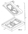
- Figure 2 is a perspective view of an apparatus in accordance with invention for making the tool case of Figure 1 .
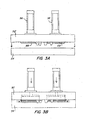
- Figure 3A is a side view of one embodiment of the apparatus of Figure 2 in an open position.
- Figure 3B is a side view of the apparatus of Figure 3A in a closed position.
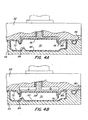
- Figure 4A is a cut-away, cross-sectional view of part of one embodiment of the apparatus of Figure 3B where a punch is in an unactivated position.
- Figure 4B is a cut-away, cross-sectional view of the apparatus of Figure 4A where a punch is in an activated position.
- FIG. 1A The basic components of one embodiment of a double wall blow molded tool case made in accordance with the invention are illustrated in Figure 1A .
- the terms “top,” “bottom,” “above,” “below,” “over,” “under,” “above,” “beneath,” “on top,” “underneath,” “up,” “down,” “upper,” “lower,” “front,” “rear,” “back,” “forward” and “backward” refer to the objects referenced when in the orientation illustrated in the drawings, which orientation is not necessary for achieving the objects of the invention.
- the case 10 includes a double wall base portion 12 and a double wall lid portion 14.
- the base portion 12 has a punched hole 20 in its inner wall 22 that corresponds to the outline of an object, such as a tool, to be housed by the tool case 10. Accordingly, the hole 20 and the space between the inner wall 22 and the outer wall 24 provide a cavity 26 in which the tool can be placed.
- the lid portion 14 includes a punched hole 30 in its inner wall 32. Accordingly, the hole 30 and the space between the inner wall 32 and outer wall 34 provide a cavity 36 for accommodating the top of the tool when the tool case 10 is closed, as shown in Figure 1B .
- the hole 30, like the hole 20 corresponds to the outline of the tool to provide a more secure fit.
- a sidewall 40 substantially perpendicular to the plane of the punched hole 20 runs along the perimeter of the hole 20, providing a press fit insertion of the tool into the cavity 26.
- an additional punched aperture 42 which may be a through hole or a blind hole, is provided to permit accessories ⁇ such as, for example, drill bits, or, as another example, a power cord ⁇ to be stored therein.
- a flange 44 is provided adjacent the hole 20 and aperture 42 in order to provide for greater rigidity.
- at least one boss 46 in the outer wall 24 is provided to engage a particular shape or aperture in the tool, such as a handle.
- one or more of the above-described features may be provided in the lid portion 14 in addition to, or in lieu of, the presence of these features in the base portion 12.
- an apparatus for creating the tool case 10 of Figure 1 comprises a mold 50 including a first mold portion 52 and a second mold portion 54.
- the first mold portion 52 includes first and second punches 56, 58 having first and second punching surfaces 66, 68, respectively.
- the first and second punches 56, 58 are in an unactivated position, as shown in Figure 3A .
- first and second punches 56, 58 remain in the unactivated position while the parison is being injected with blowing fluid. Accordingly, portions of the first and second punches 56, 58 form part of the surfaces against which the walls of the blow molded case are blown. Later, when it is desired to punch holes in the walls of the blow molded case, the first and second punches 56, 58 are moved to an activated position, as shown in phantom in Figure 3B .
- FIGs 4A-B The operation of the mold portion 52, 54 and punches 56, 58 is illustrated in Figures 4A-B .
- a cavity 70 is formed in each of the base and lid portions of the mold 50.
- the cavity 70 has a cavity surface 80 comprised of the mold surface 72 of the mold portions 52, 54 and part of the punch 56. This cavity surface 80 defines the cavity 70.
- blowing fluid is injected into the parison, the wall of the blow molded case is blown against the cavity surface 80.
- the punch 56 is moved from an unactivated position to an activated position, as illustrated in Figure 4B .
- the punch 56 is extended past the wall of the blow molded case and into the cavity 70, thereby creating a hole in the wall of the blow molded case.
- the punch 56 has a punching surface 76 corresponding to the outline of the tool to be housed in the tool case 10, and thus, a hole in the shape of the tool is created in the wall of the blow molded case 10.
- the punching surfaces of both punches 56 and 58 correspond to the outline of the tool.
- the punch 56 when the punch 56 is in the unactivated position, the punch 56 protrudes out beyond the mold surface 72 into the cavity 70, as shown in Figure 4A .
- the wall of the blow molded case 10 is blown against the cavity surface 80 (which includes part of the punch 56)
- the wall of the case 10 is formed around the punch 56.
- a recessed portion is formed in the wall of the case.
- the sidewall 40 when the punch is moved to the activated position (thereby punching the tool-shaped hole 20 in the wall of the case 10 as shown in Figure 4B ) the sidewall 40 remains along the perimeter of the tool-shaped hole 20. This permits a tighter, press-fit insertion of the tool into the cavity 26.
- the second mold portion 54 includes a boss 84 that extends into the cavity 70. Accordingly, when the wall of the blow molded case is blown against the cavity surface 80, a boss, such as boss 46, is created.
- the boss 84 corresponds to the outline of an aperture of the tool to be housed in the case 10, such as a handle.
- the first mold portion 54 includes a boss 86 so that the wall of the blow molded case 10 is formed therearound in a manner similar to boss 84, thereby producing an aperture in the wall of the case 10, such as aperture 42.
- the boss 86 is specifically configured to produce an aperture adapted to receive an accessory of the tool, such as a power cord, drill bits, etc.
- At least one additional punch is provided in addition to the first and second punches 56, 58. Like punches 56, 58, these additional punches, when in an unactivated position, form part of the cavity surface 80 and, when in an activated position, extend out beyond the mold surface 72 to create an aperture in the wall of the blow molded case.
- the aperture can be a through hole or a blind hole, and can be specifically configured to produce an aperture adapted to receive an accessory of the tool.
- the mold surface 72 includes a recess 88 adjacent the punch 56 so that, when the wall of the blow molded case is blown against the mold surface 72, flange 44 is formed, thereby providing greater rigidity to the inner wall 32 of the case 10.
Landscapes
- Engineering & Computer Science (AREA)
- Manufacturing & Machinery (AREA)
- Mechanical Engineering (AREA)
- Blow-Moulding Or Thermoforming Of Plastics Or The Like (AREA)
- Moulds For Moulding Plastics Or The Like (AREA)
- Containers Having Bodies Formed In One Piece (AREA)
Claims (26)
- Vorrichtung zur Herstellung eines blasgeformten Koffers (10) zur Aufnahme eines Objekts, aufweisend:eine Form (50) mit ersten und zweiten Formabschnitten (52, 54), die, wenn diese aneinandergrenzend angeordnet sind, erste und zweite Formoberflächen aufweisen, die zumindest teilweise erste und zweite Matrizenhohlräume (70) definieren, wobei die Matrizenhohlräume jeweils erste und zweite Matrizenhohlraumoberflächen (80) aufweisen, gegen welche erste und zweite Wände (22, 32) des blasgeformten Koffers jeweils durch Blasformen angeformt werden, dadurch gekennzeichnet, dass die Vorrichtung des weiteren aufweist:einen ersten Stempel (56) mit einer Stempeloberfläche (66), von der zumindest ein Abschnitt zumindest einem Abschnitt der Kontur des Objekts entspricht, wobei, wenn sich der erste Stempel (56) in einer Ruhestellung befindet, die erste Matrizenhohlraumoberfläche (80) die erste Formoberfläche und zumindest einen Teil des ersten Stempels (56) beinhaltet, und, wenn sich der Stempel in einer Betriebsstellung befindet, zumindest ein Teil des ersten Stempels sich über die erste Wand (12) des blasgeformten Koffers (10) hinaus und in das Innere des ersten Matrizenhohlraums erstreckt derart, dass ein erstes Loch (20), von welchem zumindest ein Abschnitt zumindest einem Abschnitt der Kontur des Objekts entspricht, in der ersten Wand (22) des blasgeformten Koffers hergestellt wird, und wobei der zweite Formabschnitt (54) zumindest einen Ansatz (84) umfasst, der sich zumindest in einen der ersten und zweiten Matrizenhohlräume (70) derart erstreckt, dass zumindest eine der ersten und zweiten Wände (22, 32) des blasgeformten Koffers (10) um diesen herum geformt wird, wobei die äußere Oberfläche des zumindest einen Ansatzes (84) einer Kontur einer Öffnung in dem Objekt entspricht.
- Vorrichtung nach Anspruch 1, des weiteren aufweisend einen zweiten Stempel (58), wobei, wenn sich der zweite Stempel (58) in einer Ruhestellung befindet, die zweite Matrizenhohlraumoberfläche (80) die zweite Formoberfläche und zumindest einen Teil des zweiten Stempels beinhaltet, und, wenn sich der zweite Stempel (58) in einer Betriebsstellung befindet, zumindest ein Teil des zweiten Stempels sich über die zweite Wand (32) des blasgeformten Koffers (10) hinaus und in das Innere des zweiten Matrizenhohlraums (70) derart erstreckt, dass ein zweites Loch (30) in der zweiten Wand (32) des blasgeformten Koffers hergestellt wird.
- Vorrichtung nach Anspruch 2, bei welcher der zweite Stempel (58) eine Stempeloberfläche (68) aufweist, von der zumindest ein Abschnitt zumindest einem Abschnitt der Kontur des Objekts derart entspricht, dass, wenn der zweite Stempel (58) von der Ruhestellung in die Betriebsstellung bewegt wird, zumindest ein Abschnitt des zweiten Lochs (30) zumindest einem Abschnitt der Kontur des Objekts entspricht.
- Vorrichtung nach einem der Ansprüche 1 bis 3, bei welcher die Kontur des Objekts die Kontur eines Werkzeugs ist.
- Vorrichtung nach einem der Ansprüche 1 bis 4, bei welcher der vollständige Umfang des ersten Lochs der vollständigen Kontur des Objekts entspricht.
- Vorrichtung nach einem der Ansprüche 1 bis 5, bei welcher, wenn sich der erste Stempel (56) in der Ruhestellung befindet, ein Teil des ersten Stempels (56) über die erste Formoberfläche in den ersten Matrizenhohlraum (70) derart hinaussteht, dass, wenn sich der erste Stempel in der Ruhestellung befindet, die erste Wand (22) des blasgeformten Koffers um diesen herum geformt wird, und, wenn sich der erste Stempel (56) in der Betriebsstellung befindet und das erste Loch (20) hergestellt wurde, eine Seitenwand (40), die der Kontur des Objekts entspricht, entlang des Umfang des Lochs (20) existiert.
- Vorrichtung nach einem der Ansprüche 1 bis 6, bei welcher der erste Formabschnitt (52) zumindest einen Ansatz (86) beinhaltet, der sich zumindest in einen der ersten und zweiten Matrizenhohlräume (70) derart erstreckt, dass zumindest eine der ersten und zweiten Wände (22, 32) des blasgeformten Koffers (10) um diesen herum geformt wird.
- Vorrichtung nach Anspruch 7, bei welcher die äußere Oberfläche des zumindest einen Ansatzes (86) konfiguriert ist, um eine Öffnung in zumindest einer der ersten und zweiten Wände (22, 32) des blasgeformten Koffers (10) auszubilden, die geeignet ist, ein Zubehör des Objekts aufzunehmen.
- Vorrichtung nach einem der Ansprüche 1 bis 8, weiter aufweisend einen zusätzlichen Stempel, wobei, wenn sich der zusätzliche Stempel in einer Ruhestellung befindet, die erste Matrizenhohlraumoberfläche (72) zumindest einen Teil des zusätzlichen Stempels beinhaltet, und, wenn sich der zusätzliche Stempel in einer Betriebsstellung befindet, sich der zusätzliche Stempel über die erste Formoberfläche hinaus um ein größeres Maß erstreckt, als wenn sich dieser in der Ruhestellung befindet, derart, dass eine Öffnung in der ersten Wand (22) hergestellt wird.
- Vorrichtung nach Anspruch 9, bei welcher, wenn sich der zusätzliche Stempel in der Betriebsstellung befindet, sich der zusätzliche Stempel über die erste Wand (22) des blasgeformten Koffers (10) hinaus und in das Innere des ersten Matrizenhohlraums (70) erstreckt.
- Vorrichtung nach Anspruch 9 oder Anspruch 10, bei welcher der zusätzliche Stempel eine Stempeloberfläche aufweist, die konfiguriert ist, um eine Öffnung in der ersten Wand (22) des blasgeformten Koffers (10) auszubilden, die geeignet ist, um ein Zubehör des Objekts aufzunehmen.
- Vorrichtung nach einem der Ansprüche 1 bis 11, bei welcher die erste Formoberfläche (72) eine Ausnehmung (88) angrenzend an den ersten Stempel (56) umfasst derart, dass ein Flansch (44) in der ersten Wand (22) des blasgeformten Koffers (10) angrenzend an das erste Loch ausgeformt wird.
- Vorrichtung nach einem der Ansprüche 1 bis 12, bei welcher der blasgeformte Koffer einen Basisabschnitt (12), der in dem ersten Matrizenhohlraum ausgeformt wird, und einen Deckelabschnitt (14) aufweist, der in dem zweiten Matrizenhohlraum ausgeformt wird.
- Verfahren zur Herstellung eines blasgeformten Koffers (10) zur Aufnahme eines Objekts, aufweisend:Bereitstellen einer Form (50) mit ersten und zweiten Formabschnitten (52, 54);Bereitstellen eines ersten Stempels (56), wobei der erste Stempel eine Stempeloberfläche (66) aufweist, von welcher zumindest ein Abschnitt zumindest einem Abschnitt der Kontur des Objektes entspricht;Bewegen des ersten Formabschnitts (52) in die Nähe des zweiten Formabschnitts (54) und dabei zumindest teilweise Einschließen der ersten und zweiten Matrizenhohlräume (70), die jeweils erste und zweite Matrizenhohlraumoberflächen (80) aufweisen;Blasformen einer ersten Wand (22) des blasgeformten Koffers (10) gegen die erste Matrizenhohlraumoberfläche (80) und einer zweiten Wand (32) des blasgeformten Koffers (10) gegen die zweite Matrizenhohlraumoberfläche (80); undAusfahren zumindest eines Teils des ersten Stempels (56) durch die erste Wand (22) des blasgeformten Koffers und in den ersten Matrizenhohlraum und dabei Ausbilden eines ersten Lochs (20) in der ersten Wand des blasgeformten Koffers, wobei der zweite Formabschnitt (54) zumindest einen Ansatz (84) umfasst, der sich zumindest in einen der ersten und zweiten Matrizenhohlräume (70) derart erstreckt, dass zumindest eine der ersten und zweiten Wände (22, 32) um diesen herum ausgebildet wird, wenn gegen zumindest eine der ersten und zweiten Matrizenhohlraumoberflächen (80) blasgeformt wird, und wobei die äußere Oberfläche des zumindest einen Ansatzes (84) einer Kontur einer Öffnung in dem Objekt entspricht.
- Verfahren nach Anspruch 14, weiter aufweisend die Schritte:Bereitstellen eines zweiten Stempels (58); undAusfahren zumindest einen Teils des zweiten Stempels (58) durch die zweite Wand (32) des blasgeformten Koffers und in den zweiten Matrizenhohlraum und dabei Ausbilden eines zweiten Lochs (30) in der zweiten Wand (32) des blasgeformten Koffers.
- Verfahren nach Anspruch 15, bei welchem der zweite Stempel (58) eine Stempeloberfläche (68) aufweist, von welcher zumindest ein Abschnitt zumindest einem Abschnitt der Kontur des Objekts entspricht.
- Verfahren nach einem der Ansprüche 14 bis 16, bei welchem die Kontur des Objekts die Kontur eines Werkzeugs ist.
- Verfahren nach einem der Ansprüche 14 bis 17, bei welchem der vollständige Umfang des ersten Lochs (22) der vollständigen Kontur des Objekts entspricht.
- Verfahren nach einem der Ansprüche 14 bis 18, bei welchem der erste Formabschnitt (52) eine erste Formoberfläche aufweist, die zumindest teilweise den ersten Matrizenhohlraum (70) definiert, weiter aufweisend
Positionieren des ersten Stempels (56) derart, dass sich ein Teil des ersten Stempels über die erste Formoberfläche hinaus in den ersten Matrizenhohlraum erstreckt, wenn die erste Wand (22) gegen die erste Matrizenhohlraumoberfläche blasgeformt wird, so dass die erste Wand (22) um diesen herum ausgeformt wird, und, so dass, wenn zumindest ein Teil des ersten Stempels (52) sich durch die erste Wand erstreckt und dabei das erste Loch (20) ausgebildet wird, eine Seitenwand (40), die der Kontur des Objekts entspricht, entlang des Umfangs des ersten Lochs (20) existiert. - Verfahren nach einem der Ansprüche 14 bis 19, bei welchem der erste Formabschnitt (52) zumindest einen Ansatz (86) beinhaltet, der sich zumindest in einen der ersten und zweiten Matrizenhohlräume (70) derart erstreckt, dass zumindest eine der ersten und zweiten Wände (22, 32) um diesen herum ausgeformt wird, wenn gegen zumindest eine der ersten und zweiten Matrizenhohlraumoberflächen (80) blasgeformt wird.
- Verfahren nach Anspruch 20, bei welchem die äußere Oberfläche des zumindest einen Ansatzes (86) konfiguriert ist, um eine Öffnung in zumindest einer der ersten und zweiten Wände (22, 32) auszubilden, die geeignet ist, um ein Zubehör des Objekts aufzunehmen.
- Verfahren nach einem der Ansprüche 14 bis 21, bei welchem der erste Formabschnitt (52) eine erste Formoberfläche aufweist, die zumindest teilweise den ersten Matrizenhohlraum (70) definiert, weiter aufweisend:Bereitstellen eines zusätzlichen Stempels in einer Ruhestellung; undAusfahren des zusätzlichen Stempels über die erste Formoberfläche hinaus um ein größeres Maß, als wenn sich dieser in der Ruhestellung befindet, und dabei Ausbilden einer Öffnung in der ersten Wand (22).
- Verfahren nach Anspruch 22, bei welchem der Schritt des Ausfahrens des zusätzlichen Stempels umfasst:Ausfahren des zusätzlichen Stempels über die erste Wand (22) des blasgeformten Koffers (10) hinaus und in den ersten Matrizenhohlraum.
- Verfahren nach Anspruch 22 oder Anspruch 23, bei welchem der zusätzliche Stempel eine Stempeloberfläche aufweist, die konfiguriert ist, um eine Öffnung in der ersten Wand (22) auszubilden, die geeignet ist, um ein Zubehör des Objekts aufzunehmen.
- Verfahren nach einem der Ansprüche 14 bis 24, bei welchem die ersten und zweiten Formabschnitte (52, 54) eine erste Formoberfläche (72) aufweisen, die zumindest teilweise den ersten Matrizenhohlraum (70) definiert, weiter aufweisend:Bereitstellen einer Ausnehmung (88) angrenzend an den ersten Stempel, so dass ein Flansch (44) in der ersten Wand angrenzend an das erste Loch ausgebildet wird.
- Verfahren nach einem der Ansprüche 14 bis 25, bei welchem der blasgeformte Koffer einen Basisabschnitt (12), der in dem ersten Matrizenhohlraum ausgeformt wird, und einen Deckelabschnitt (14) aufweist, der in dem zweiten Matrizenhohlraum ausgeformt wird.
Applications Claiming Priority (1)
| Application Number | Priority Date | Filing Date | Title |
|---|---|---|---|
| US10/958,824 US20060073289A1 (en) | 2004-10-05 | 2004-10-05 | Blow molded case and method and apparatus for creating same |
Publications (3)
| Publication Number | Publication Date |
|---|---|
| EP1645397A2 EP1645397A2 (de) | 2006-04-12 |
| EP1645397A3 EP1645397A3 (de) | 2008-06-25 |
| EP1645397B1 true EP1645397B1 (de) | 2010-09-15 |
Family
ID=35614194
Family Applications (1)
| Application Number | Title | Priority Date | Filing Date |
|---|---|---|---|
| EP05256209A Expired - Lifetime EP1645397B1 (de) | 2004-10-05 | 2005-10-05 | Vorrichtung zur Herstellung eines Koffers |
Country Status (4)
| Country | Link |
|---|---|
| US (3) | US20060073289A1 (de) |
| EP (1) | EP1645397B1 (de) |
| CN (1) | CN1817617B (de) |
| DE (1) | DE602005023565D1 (de) |
Families Citing this family (18)
| Publication number | Priority date | Publication date | Assignee | Title |
|---|---|---|---|---|
| US20060290492A1 (en) * | 2005-06-28 | 2006-12-28 | Jidas Forrest P | Gun case with alarm |
| US8857351B2 (en) | 2005-08-25 | 2014-10-14 | Custom-Pak, Inc. | Modular support assembly with fortifying flange |
| US20070235423A1 (en) * | 2006-04-04 | 2007-10-11 | Bornemann Brian J | Protective case for plasma cutter |
| US7905305B2 (en) * | 2006-07-07 | 2011-03-15 | Mattel, Inc. | Blow-molded wheels having undulating treads, methods for producing the same, and children's ride-on vehicles including the same |
| US20080079198A1 (en) * | 2006-10-03 | 2008-04-03 | Custom-Pak, Inc. | Dynamic device and method for forming a blow-molded article |
| CA2682142C (en) * | 2007-03-28 | 2013-01-22 | Custom-Pak, Inc. | Soft plastic insert for use in protective case |
| US8037649B2 (en) * | 2007-03-29 | 2011-10-18 | Vermont Juvenile Furniture Mfg., Inc. | Portable steps |
| US7523516B1 (en) | 2008-02-29 | 2009-04-28 | Skamper Industries Llc | Extended water escape ramp device for animals |
| DE102009001491B4 (de) * | 2009-03-11 | 2025-11-27 | Robert Bosch Gmbh | Werkzeugkoffer |
| CN101987504B (zh) * | 2010-08-09 | 2012-06-27 | 无锡吉兴汽车声学部件科技有限公司 | 聚丙烯粒子熔融吹气成型的制作行李箱的生产工艺 |
| US10272561B2 (en) | 2013-09-26 | 2019-04-30 | Custom-Pak, Inc. | Hybrid single and double wall chainsaw case |
| JP6068756B2 (ja) * | 2014-03-18 | 2017-01-25 | 豊田鉄工株式会社 | 分岐部付き中空部品の製造方法および製造装置 |
| CN103921430B (zh) * | 2014-04-08 | 2016-03-23 | 宁波方正汽车模具有限公司 | 一种吹塑模具的自动冲孔装置 |
| WO2015184647A1 (en) * | 2014-06-06 | 2015-12-10 | Techtronic Industries Company Limited | Blow molded container |
| USD780385S1 (en) * | 2015-10-15 | 2017-02-28 | Vermont Juvenile Furniture Mfg., Inc. | Pet step |
| USD906674S1 (en) * | 2019-02-26 | 2021-01-05 | Threaded Bliss, LLC | Layered insert |
| USD906675S1 (en) * | 2019-02-26 | 2021-01-05 | Threaded Bliss, LLC | Layered insert |
| USD906676S1 (en) * | 2019-02-27 | 2021-01-05 | Threaded Bliss, LLC | Layered insert |
Family Cites Families (20)
| Publication number | Priority date | Publication date | Assignee | Title |
|---|---|---|---|---|
| US3263009A (en) * | 1959-12-29 | 1966-07-26 | Phillips Petroleum Co | Method of making a carrying case |
| US3327841A (en) * | 1964-09-09 | 1967-06-27 | Grace W R & Co | Plastic container |
| US3339781A (en) * | 1965-03-22 | 1967-09-05 | Grace W R & Co | Hollow wall container |
| SE314188B (de) * | 1964-05-21 | 1969-09-01 | Grace W R & Co | |
| US3317955A (en) * | 1964-12-21 | 1967-05-09 | Grace W R & Co | Apparatus for blow molding hollow containers |
| US3317995A (en) * | 1965-03-11 | 1967-05-09 | Bord Max | Slidable blade type safety razor having an adjustable razor head and blade exposure means |
| US3822083A (en) * | 1973-02-08 | 1974-07-02 | Scm Corp | Typewriter case |
| US4166833A (en) * | 1973-10-23 | 1979-09-04 | The Plastic Forming Company, Inc. | Method and apparatus for molding a plastic article |
| US3933381A (en) * | 1974-11-04 | 1976-01-20 | The Plastic Forming Company, Inc. | Plastic container and latch |
| US4340139A (en) * | 1981-02-19 | 1982-07-20 | Show-Pak, Incorporated | Blow molded carrying case |
| JPS61171322A (ja) * | 1985-01-24 | 1986-08-02 | Mazda Motor Corp | プラスチツクタンクの製造方法 |
| WO1999002322A2 (en) * | 1997-07-14 | 1999-01-21 | Confer Plastics, Inc. | Blow molded articles and method of making |
| US6375891B1 (en) * | 1997-07-18 | 2002-04-23 | Asmo Co., Ltd. | Method of manufacturing a resinous tank |
| CN2385853Y (zh) * | 1999-08-06 | 2000-07-05 | 刘煌 | 结构改良的工具箱 |
| US6267238B1 (en) * | 1999-12-30 | 2001-07-31 | Hand Tools International, Llc | Case for power tool having attached power cord |
| FR2817790B1 (fr) * | 2000-12-11 | 2003-02-28 | Normatec | Procede et dispositif de formation d'une bonde ainsi que moule de fabrication d'un corps creux equipe d'un tel dispositif |
| CN1169663C (zh) * | 2001-08-22 | 2004-10-06 | 刘煌 | 工具箱吹塑制品铰链成型方法 |
| US20030104098A1 (en) * | 2001-11-30 | 2003-06-05 | Brent Schrader | Formation of punched, blind holes through one wall of a double wall blow molded structure |
| US7229587B2 (en) * | 2003-04-03 | 2007-06-12 | Custom - Pak, Inc. | Blow molded container having holes therein and method and apparatus for facilitating the creation thereof |
| US20050084648A1 (en) * | 2003-10-16 | 2005-04-21 | Olsen Robert F. | Process for forming a part having an integral feature, a part produced thereby and apparatus therefor |
-
2004
- 2004-10-05 US US10/958,824 patent/US20060073289A1/en not_active Abandoned
-
2005
- 2005-04-14 US US11/105,721 patent/US20060073290A1/en not_active Abandoned
- 2005-10-05 EP EP05256209A patent/EP1645397B1/de not_active Expired - Lifetime
- 2005-10-05 DE DE602005023565T patent/DE602005023565D1/de not_active Expired - Lifetime
- 2005-10-08 CN CN200510116537.5A patent/CN1817617B/zh not_active Expired - Fee Related
-
2008
- 2008-01-18 US US12/016,729 patent/US7578959B2/en not_active Expired - Lifetime
Also Published As
| Publication number | Publication date |
|---|---|
| CN1817617B (zh) | 2010-12-08 |
| US20060073290A1 (en) | 2006-04-06 |
| DE602005023565D1 (de) | 2010-10-28 |
| EP1645397A2 (de) | 2006-04-12 |
| US20080111285A1 (en) | 2008-05-15 |
| US7578959B2 (en) | 2009-08-25 |
| US20060073289A1 (en) | 2006-04-06 |
| CN1817617A (zh) | 2006-08-16 |
| EP1645397A3 (de) | 2008-06-25 |
Similar Documents
| Publication | Publication Date | Title |
|---|---|---|
| US7578959B2 (en) | Method and apparatus for creating a blow molded case | |
| US20090065515A1 (en) | Blow Molded Case and System for Creating Same | |
| US7422269B2 (en) | Multi-insert cap blow-molding method and spoiler for vehicle manufactured using the same | |
| CA2426788A1 (en) | Method of making a can having a recessed base | |
| US7727455B2 (en) | Apparatus and method for creation of a blow molded container having holes therein | |
| US6808674B1 (en) | Enclosed area on a blow molded article and method of making the same | |
| JP2010076297A (ja) | ブロー成形品の開口部形成方法 | |
| CN105799121A (zh) | 一种汽车工程模具 | |
| EP0736245A1 (de) | Aus Kunststoff hergestellte Schutzhülle, beziehungsweise für Heckenschereklingen, und Verfahren zu deren Herstellung | |
| JP2006205686A (ja) | 合成樹脂製中空体および合成樹脂製中空体の補強材挿入口加工方法 | |
| US8283007B2 (en) | Blow molded receptacle and system for making same | |
| JP3644676B2 (ja) | 中空成形品の不要部分型内切断方法 | |
| CN104842522B (zh) | 汽油锯前挡板的加工模具 | |
| JP3201494U (ja) | 金型装置 | |
| CN216782547U (zh) | 一种汽车内饰塑胶件高精度塑胶模具 | |
| CN208946574U (zh) | 一种高熔点塑料的注塑模结构 | |
| JPH09216259A (ja) | 内壁に凹陥部が形成されたプラスチック筒の成形方法とその装置 | |
| JPH07125058A (ja) | 中空成形品の孔形成方法 | |
| KR19990021544U (ko) | 냉장고의 도어 트리밍 지그 | |
| JP2016112730A (ja) | ブロー成形方法 | |
| CN113352549A (zh) | 一种加快注塑模具冷却的结构 | |
| JP2005205621A (ja) | ブロー成形パネル | |
| JP2005297369A (ja) | 合成樹脂製容器及びその製造方法並びに金型 | |
| JPH0994844A (ja) | 中空状成形品製造装置および中空状成形品製造方法 | |
| JPH11334669A (ja) | 巻掛伝動体ケースとその製造方法及び装置 |
Legal Events
| Date | Code | Title | Description |
|---|---|---|---|
| PUAI | Public reference made under article 153(3) epc to a published international application that has entered the european phase |
Free format text: ORIGINAL CODE: 0009012 |
|
| 17P | Request for examination filed |
Effective date: 20051025 |
|
| AK | Designated contracting states |
Kind code of ref document: A2 Designated state(s): AT BE BG CH CY CZ DE DK EE ES FI FR GB GR HU IE IS IT LI LT LU LV MC NL PL PT RO SE SI SK TR |
|
| AX | Request for extension of the european patent |
Extension state: AL BA HR MK YU |
|
| PUAL | Search report despatched |
Free format text: ORIGINAL CODE: 0009013 |
|
| AK | Designated contracting states |
Kind code of ref document: A3 Designated state(s): AT BE BG CH CY CZ DE DK EE ES FI FR GB GR HU IE IS IT LI LT LU LV MC NL PL PT RO SE SI SK TR |
|
| AX | Request for extension of the european patent |
Extension state: AL BA HR MK YU |
|
| AKX | Designation fees paid |
Designated state(s): DE FR GB |
|
| 17Q | First examination report despatched |
Effective date: 20090217 |
|
| RTI1 | Title (correction) |
Free format text: BLOW MOLDING METHOD AND APPARATUS FOR CREATING A CASE |
|
| RTI1 | Title (correction) |
Free format text: APPARATUS FOR CREATING A CASE |
|
| GRAP | Despatch of communication of intention to grant a patent |
Free format text: ORIGINAL CODE: EPIDOSNIGR1 |
|
| GRAC | Information related to communication of intention to grant a patent modified |
Free format text: ORIGINAL CODE: EPIDOSCIGR1 |
|
| GRAS | Grant fee paid |
Free format text: ORIGINAL CODE: EPIDOSNIGR3 |
|
| GRAA | (expected) grant |
Free format text: ORIGINAL CODE: 0009210 |
|
| AK | Designated contracting states |
Kind code of ref document: B1 Designated state(s): DE FR GB |
|
| REG | Reference to a national code |
Ref country code: GB Ref legal event code: FG4D |
|
| REF | Corresponds to: |
Ref document number: 602005023565 Country of ref document: DE Date of ref document: 20101028 Kind code of ref document: P |
|
| PLBE | No opposition filed within time limit |
Free format text: ORIGINAL CODE: 0009261 |
|
| STAA | Information on the status of an ep patent application or granted ep patent |
Free format text: STATUS: NO OPPOSITION FILED WITHIN TIME LIMIT |
|
| 26N | No opposition filed |
Effective date: 20110616 |
|
| REG | Reference to a national code |
Ref country code: DE Ref legal event code: R097 Ref document number: 602005023565 Country of ref document: DE Effective date: 20110616 |
|
| REG | Reference to a national code |
Ref country code: FR Ref legal event code: PLFP Year of fee payment: 11 |
|
| REG | Reference to a national code |
Ref country code: FR Ref legal event code: PLFP Year of fee payment: 12 |
|
| REG | Reference to a national code |
Ref country code: FR Ref legal event code: PLFP Year of fee payment: 13 |
|
| REG | Reference to a national code |
Ref country code: FR Ref legal event code: PLFP Year of fee payment: 14 |
|
| P01 | Opt-out of the competence of the unified patent court (upc) registered |
Effective date: 20230530 |
|
| PGFP | Annual fee paid to national office [announced via postgrant information from national office to epo] |
Ref country code: GB Payment date: 20230927 Year of fee payment: 19 |
|
| PGFP | Annual fee paid to national office [announced via postgrant information from national office to epo] |
Ref country code: FR Payment date: 20240821 Year of fee payment: 20 |
|
| PGFP | Annual fee paid to national office [announced via postgrant information from national office to epo] |
Ref country code: DE Payment date: 20240820 Year of fee payment: 20 |
|
| GBPC | Gb: european patent ceased through non-payment of renewal fee |
Effective date: 20241005 |
|
| PG25 | Lapsed in a contracting state [announced via postgrant information from national office to epo] |
Ref country code: GB Free format text: LAPSE BECAUSE OF NON-PAYMENT OF DUE FEES Effective date: 20241005 |
|
| REG | Reference to a national code |
Ref country code: DE Ref legal event code: R071 Ref document number: 602005023565 Country of ref document: DE |