EP1645703A2 - Türschlossanordnung und Kupplung für eine Türschlossanordnung - Google Patents
Türschlossanordnung und Kupplung für eine Türschlossanordnung Download PDFInfo
- Publication number
- EP1645703A2 EP1645703A2 EP05021716A EP05021716A EP1645703A2 EP 1645703 A2 EP1645703 A2 EP 1645703A2 EP 05021716 A EP05021716 A EP 05021716A EP 05021716 A EP05021716 A EP 05021716A EP 1645703 A2 EP1645703 A2 EP 1645703A2
- Authority
- EP
- European Patent Office
- Prior art keywords
- coupling
- door lock
- lock arrangement
- clutch
- spring assembly
- Prior art date
- Legal status (The legal status is an assumption and is not a legal conclusion. Google has not performed a legal analysis and makes no representation as to the accuracy of the status listed.)
- Withdrawn
Links
Images


Classifications
-
- E—FIXED CONSTRUCTIONS
- E05—LOCKS; KEYS; WINDOW OR DOOR FITTINGS; SAFES
- E05B—LOCKS; ACCESSORIES THEREFOR; HANDCUFFS
- E05B17/00—Accessories in connection with locks
- E05B17/0054—Fraction or shear lines; Slip-clutches, resilient parts or the like for preventing damage when forced or slammed
- E05B17/0058—Fraction or shear lines; Slip-clutches, resilient parts or the like for preventing damage when forced or slammed with non-destructive disengagement
-
- E—FIXED CONSTRUCTIONS
- E05—LOCKS; KEYS; WINDOW OR DOOR FITTINGS; SAFES
- E05B—LOCKS; ACCESSORIES THEREFOR; HANDCUFFS
- E05B47/00—Operating or controlling locks or other fastening devices by electric or magnetic means
- E05B47/06—Controlling mechanically-operated bolts by electro-magnetically-operated detents
- E05B47/0676—Controlling mechanically-operated bolts by electro-magnetically-operated detents by disconnecting the handle
- E05B47/068—Controlling mechanically-operated bolts by electro-magnetically-operated detents by disconnecting the handle axially, i.e. with an axially disengaging coupling element
-
- E—FIXED CONSTRUCTIONS
- E05—LOCKS; KEYS; WINDOW OR DOOR FITTINGS; SAFES
- E05B—LOCKS; ACCESSORIES THEREFOR; HANDCUFFS
- E05B15/00—Other details of locks; Parts for engagement by bolts of fastening devices
- E05B15/04—Spring arrangements in locks
- E05B2015/0465—Cup- or dished-disc springs
-
- E—FIXED CONSTRUCTIONS
- E05—LOCKS; KEYS; WINDOW OR DOOR FITTINGS; SAFES
- E05B—LOCKS; ACCESSORIES THEREFOR; HANDCUFFS
- E05B65/00—Locks or fastenings for special use
- E05B65/10—Locks or fastenings for special use for panic or emergency doors
- E05B65/1086—Locks with panic function, e.g. allowing opening from the inside without a ley even when locked from the outside
Definitions
- the invention relates to a door lock arrangement, in particular a panic lock arrangement, with an electromechanical coupling for locking or releasing a door handle of the door lock arrangement for actuating the door lock arrangement. Furthermore, the invention relates to a coupling for a door lock, in particular a panic lock, which has a split mandrel, in particular a square, for receiving in each case a door handle.
- the door handle By means of the electromechanical coupling, the door handle can be switched to a locked or released state. In the locked state, no actuation of the door lock arrangement is possible by means of the door handle, so that a door equipped with it can not be opened by a person.
- the locked state may be e.g. then be brought about if a person does not have sufficient access authorization.
- an operation of the door lock assembly by means of the door handle is possible in the released state.
- the released state can be brought about, for example, if a person can provide sufficient access authorization.
- the invention is therefore based on the invention to provide a door lock assembly and a coupling for a door lock assembly, by which the risk of damage to the door lock assembly can be reduced.
- the basic idea of the invention is thus to provide, in addition to the electromechanical clutch, an overload clutch which is connected upstream of the electromechanical clutch.
- a nominal torque can be specified, beyond which the overload clutch disengages.
- the nominal torque of the overload clutch is set so that damage to the electromechanical clutch or the door lock assembly is avoided in any case. This can be done, for example, that the rated torque of the overload clutch corresponds to the maximum permissible torque of the electromechanical clutch, in which no damage to the electromechanical clutch occurs.
- the rated torque compared to the maximum permissible torque of the electromechanical clutch can be provided with a safety discount.
- the nominal torque of the overload clutch should expediently be selected so that minimum values for the torque transmission for the respective present door lock arrangement are met. For example, in panic locks it is usually required that a torque of at least 7 Nm can be transmitted between the split mandrels. In this case, the size of the rated torque should be at least 7 Nm.
- an overload clutch basically all known from the prior art overload clutches, which are suitable for use in a door lock assembly can be used.
- the overload clutch is designed such that its rated torque is adjustable. This has the advantage that such overload clutch is flexible adjustable for different door lock arrangements and thus can be used universally.
- the overload clutch is designed as a slip clutch.
- Such a coupling is particularly suitable for use in the door lock assembly according to the invention, since this coupling effectively and reliably separates the adhesion between the mandrel parts upon reaching the rated torque.
- the clutch disengages after disengaging again when the torque acting on the door lock assembly is again smaller than the predetermined nominal torque.
- the normal functionality of the door lock assembly is provided again as soon as the applied torque is smaller than the predetermined nominal torque and thus there is no longer a risk of damage to the electromechanical coupling.
- a coupling for a door lock arrangement in particular a panic lock arrangement, which has a split mandrel, in particular a split square, for receiving in each case a door handle, wherein at the opposite ends of the split mandrel two positively plugged coupling halves are provided , The two coupling halves are pressed together by means of a spring assembly and biased and the coupling is formed in such a way that disengage the two coupling halves as soon as a torque acts on the clutch that is greater than the holding force or contact force of the spring assembly.
- Advantageous embodiments are specified in the claims dependent on claim 5.
- the basic idea of the invention is thus to apply a spring force to the coupling, with the coupling disengaging as soon as the force applied to the coupling is greater than the spring force.
- the force of the spring thus specifies the maximum force or the maximum torque (nominal torque) with which the clutch can be acted upon without it disengaging. This avoids that the door lock assembly is damaged if too large torques are applied to it.
- different nominal torques for the coupling can be specified.
- the spring assembly is designed so that its holding or contact pressure and thus the nominal torque and the disengagement of the clutch by means of an actuator are adjustable.
- An actuator may be, for example, a set screw or an adjusting nut. The adjustment can be made steplessly or stepwise.
- the spring assembly is designed as a plate spring.
- This type of spring is particularly suitable for the coupling according to the invention, since this results in an extremely compact arrangement. This is advantageous because only a limited space is available in door lock arrangements.
- At least one contact surface of one of the coupling halves is at least partially formed as a wedge surface and the contact surfaces of the two coupling halves form a wedge gear in such a way that when disengaging the clutch, a movable coupling half slides along the wedge surfaces and thereby move against the effective direction the contact pressure of the spring package executes, whereby the spring assembly is additionally loaded.
- the basic idea in this embodiment is therefore that at least one contact surface of a coupling half is formed at least partially in the manner of an inclined plane. If the external torque exceeds the rated torque, the movable coupling half slides along the wedge surface.
- the wedge surface thus also acts simultaneously as a control surface, which sets the direction of movement or the rotation of the two coupling halves against each other.
- the advantage here is that by sliding along the wedge surface, the movable coupling half performs a movement against the contact force of the spring assembly, which adjusts an additional burden of the spring assembly.
- the wedge or control surfaces are thus designed so that a corresponding movement of the movable coupling half is established. This additional load ensures that once the external torque is reduced, the movable coupling half slides back to its original position. The door handle is thus automatically turned back to the starting position.
- wedge or control surfaces which correspond to one another are provided on both coupling halves.
- Wedge surfaces can be both linear and different, such as curved, be formed.
- the degree of curvature of a curved wedge surface can be predetermined, for example, as a function of a gradient. From the formation of the wedge surfaces depends on how the control cam on the Verwindweg the two coupling halves looks against each other. If, for example, the at least one wedge surface is linear, a constant force curve over the entire control curve results.
- it is therefore possible to influence the magnitude of the force which is required in certain stages of the movement for example, the start or end point of the control cam
- the contact surfaces of the coupling halves each have a conical shape, wherein the tapered region is in each case approximately in the middle of the coupling half. It is advantageous here that a self-centering of the two coupling halves is achieved, so that they can not slip in the twisting plane against each other or move in the case of rotation. As a result, therefore, can be dispensed with the use of brackets, housings or the like for fixing the position in the plane of rotation.
- the coupling is designed so that the movement when disengaging the clutch against the effective direction of the contact pressure of the spring assembly is an axial movement along the mandrel of the door opener assembly.
- the coupling halves are arranged in this embodiment, approximately orthogonal to the mandrel of the door opener arrangement and the wedge surfaces extend substantially in the circumferential direction of the coupling halves.
- the coupling In order to achieve a compact design of the door lock assembly, it is expedient to form the coupling so that it can be arranged in an outer fitting of the door lock assembly. This is also optically advantageous, since this conceals a user the presence of the coupling and this perceives only the outer fitting and thus a closed unit.
- the coupling can be arranged both in the door inside as well as in the outside door outside door fitting.
- the coupling In a panic lock the coupling is preferably arranged in the outer fitting, which is located on the panic side.
- the coupling can be used with any known door lock arrangement.
- the clutch is used as an overload clutch in such a door lock assembly having an electromechanical coupling for locking or releasing a door handle of the door lock assembly for actuating the door lock assembly.
- the coupling is connected upstream of the electromechanical coupling and disengages when a specified nominal torque is exceeded.
- a stop for the rotary movement of the door handle is normally provided, so that a maximum angle of rotation is predetermined.
- the wedge surfaces are formed such that the sliding path of the wedge surfaces or its control curve is at least as long as the sliding path, which corresponds to the maximum angle of rotation. This ensures that even at the maximum angle of rotation of the door handle, the movable coupling half does not slide over a wedge surface. Otherwise, the additional burden of the spring package could be reduced. This embodiment thus ensures at all times that the additional holding force of the spring assembly is sufficient to return the coupling halves, after reducing the external torque, back to the starting position.
- FIG. 1 shows the same door lock arrangement in a horizontal section.
- the two four-edge 1, 1 ' are interconnected via a designed as a slip clutch overload clutch 12.
- the coupling 12 comprises two coupling halves 6, 7, which can be plugged into one another in a form-fitting manner and which are each attached to one of the opposite ends of the divided square edge 1, 1 '.
- the two coupling halves 6, 7 each have an inner contact surface 9, 10, with which the two coupling halves 6, 7 lie positively against one another.
- the two coupling halves 6, 7 are pressed together by means of a spring assembly 8, which is designed as a plate spring, and biased.
- the contact surface 9 is bordered by the end of a coupling half 6 belonging to the sleeve 13.
- This sleeve 13 serves as a housing for the clutch 12 and encloses both the other coupling half 7 and the plate spring 8. It ensures that the two coupling halves 6, 7 in the radial direction, relative to the longitudinal direction of the square 1, 1 ', do not slip against each other or move.
- the sleeve 13 is thus at the same time housing and guide.
- At the free end 4 of the square 1 is in the longitudinal direction approximately centrally before a substantially cylindrical nose 14 before. This nose 14 is designed to engage in a recess 15 which is provided at the free end 5 of the square 1 '.
- the nose 14 engages in the recess 15 and thus prevents the four-edge 1, 1 'can be moved in the transverse direction against each other. A rotation of the four-edge 1, 1 'against each other, however, is not hindered by the introduced into the recess 15 nose 14. Further, the nose 14 serves to position the two square edge 1, 1 ', when the clutch 12 is assembled for the first time.
- Figure 3 shows a detailed view of the coupling 12, as shown in Figure 2.
- the contact surface 9 of the coupling half 6 consists of a plurality of wedge surfaces 11 arranged one behind the other in the circumferential direction.
- the wedge surfaces 11 are each formed of the same size and distributed uniformly over the contact surface 9 in the circumferential direction. They each run as inclined planes with respect to the plane of rotation, which extends between the two coupling halves 6, 7 and perpendicular to the longitudinal axis of the mandrel 1, 1 ' stands.
- the wedge surfaces 11 thus extend obliquely to this plane of rotation.
- the pitch of the individual wedge surfaces 11 is oriented so that a wedge surface 11 extends into the coupling half 6 and its two adjacent wedge surfaces 11 each again out of this and vice versa.
- This results in the circumferential direction of the contact surface 9 of the coupling half 6 is a kind of uniform wave profile having mountains 16 and valleys 17.
- the contact surface 10 of the movable coupling half 7 is also provided with wedge surfaces, which also form a wave profile with mountains 16 'and valleys 17'.
- the movable coupling half 7 slides on the wedge surfaces 11 of the contact surface 9 of the other coupling half 6 along.
- the two coupling halves 6, 7 are thus rotated against each other.
- the movable coupling half 7 carries out an axial movement out of the other coupling half 6 and thereby additionally loads the spring assembly 8, which is further compressed.
- the plate spring 8 relaxes again and pushes the movable coupling half 7 in the axial direction into the other coupling half 6.
- the movable coupling half 7 thus slides back on the wedge surfaces 11, up to their starting position.
- FIGS. 4 and 5 likewise show a partial view of the coupling 12, wherein the coupling 12 is cut horizontally.
- the clutch 12 is in the assembled state, that is, the coupling halves 6, 7 are pressed together by the plate spring 8 and all three components are enclosed by the sleeve 13 of the coupling half 6.
- the ends 4, 5 of the mandrel 1, 1 ' are located within the coupling 12 and the nose 14 of the mandrel 1 is inserted into the recess 15 of the mandrel 1'.
- the clutch 12 is not assembled in the illustration in Figure 5 and the movable coupling half 7 is spaced from the coupling half 6.
- the plate spring 8 and the coupling half 7 are located outside of the sleeve 13 of the coupling half. 6
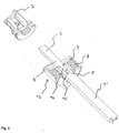
- Figure 6 shows a perspective view of a door lock assembly with two door handles 2, 3 and an overload clutch 12 in the assembled state.
- an electromechanical coupling (not shown here) can be arranged in the free area of the mandrel part 1 '.
- the mandrel part 1 ' can be divided again in the area of the electromechanical coupling.
Landscapes
- Lock And Its Accessories (AREA)
Abstract
Description
- Die Erfindung betrifft eine Türschlossanordnung, insbesondere eine Panikschlossanordnung, mit einer elektromechanischen Kupplung zum Sperren bzw. Freigeben eines Türdrückers der Türschlossanordnung zur Betätigung der Türschlossanordnung. Ferner betrifft die Erfindung eine Kupplung für ein Türschloss, insbesondere ein Panikschloss, welches einen geteilten Dorn, insbesondere einen Vierkant, zur Aufnahme jeweils eines Türdrückers aufweist.
- Derartige Türöffneranordnungen sind aus dem Stand der Technik hinreichend bekannt. Mittels der elektromechanischen Kupplung kann der Türdrücker in einen gesperrten bzw. freigegebenen Zustand geschaltet werden. Im gesperrten Zustand ist mittels des Türdrückers keine Betätigung der Türschlossanordnung möglich, so dass eine damit ausgerüstete Tür von einer Person nicht geöffnet werden kann. Der gesperrte Zustand kann z.B. dann herbeigeführt werden, wenn eine Person nicht über eine ausreichende Zutrittsberechtigung verfügt. Demgegenüber ist im freigegebenen Zustand eine Bedienung der Türschlossanordnung mittels des Türdrückers möglich. Der freigegebene Zustand kann beispielsweise dann herbeigeführt werden, wenn eine Person eine ausreichende Zutrittsberechtigung vorweisen kann.
- Bei Türschlossanordnungen der oben genannten Art und insbesondere bei Panikschlossanordnungen kann das Problem auftreten, dass über die Türdrücker (Außen- und Innendrücker) sehr große Drehmomente auf die Schlossanordnung aufgebracht werden, die unter Umständen von der elektromechanischen Kupplung nicht übertragen werden können. Dies kann dann zu einer Zerstörung der elektromechanischen Kupplung bzw. der Schlossanordnung führen. So wird beispielsweise von der Materialprüfanstalt gefordert, dass Panikschlösser, trotz eines Drehmoments von 50 Nm, dass auf den Dorn einwirkt, nicht zerstört werden. Besonders problematisch kann es in Situationen werden, bei der ein großes Drehmoment auf die Schlossanordnung aufgebracht wird und gleichzeitig dieses Drehmoment nicht über die festen Anschläge an den Beschlägen der Schlossanordnung aufgenommen werden kann. Dies kann beispielsweise dann der Fall sein, wenn der Außendrücker von einer Person blockiert bzw. festgehalten wird und zur selben Zeit eine weitere Person auf den Innendrücker ein großes Drehmoment aufbringt.
- Der Erfindung liegt daher die A u f g a b e zugrunde, eine Türschlossanordnung sowie eine Kupplung für eine Türschlossanordnung anzugeben, durch die die Gefahr einer Beschädigung der Türschlossanordnung reduziert werden.
- Die Lösung dieser Aufgabe gelingt mit einer Türschlossanordnung, die die Merkmale des Anspruchs 1 aufweist. Vorteilhafte Ausführungsformen der Türschlossanordnung sind in den vom Anspruch 1 abhängigen Ansprüchen angegeben.
- Der Grundgedanke der Erfindung besteht also darin, zusätzlich zur elektromechanischen Kupplung eine Überlastkupplung vorzusehen, die der elektromechanischen Kupplung vorgeschaltet ist. Bei der Überlastkupplung ist ein Nenndrehmoment vorgebbar, bei dessen Überschreitung die Überlastkupplung auskuppelt. Durch die Auskupplung wird also die Kraftübertragung zwischen den beiden Türdrückern aufgehoben und das von außen auf die Türschlossanordnung eingeleitete Drehmoment wirkt nicht mehr auf die elektromechanische Kupplung und kann diese somit auch nicht mehr beschädigen. Zweckmäßigerweise wird das Nenndrehmoment der Überlastkupplung so vorgegeben, dass eine Beschädigung der elektromechanischen Kupplung bzw. der Türschlossanordnung in jedem Fall vermieden wird. Dies kann beispielsweise dadurch geschehen, dass das Nenndrehmoment der Überlastkupplung dem maximal zulässigen Drehmoment der elektromechanischen Kupplung entspricht, bei dem noch keine Beschädigung der elektromechanischen Kupplung auftritt. Auch kann das Nenndrehmoment gegenüber dem maximal zulässigen Drehmoment der elektromechanischen Kupplung mit einem Sicherheitsabschlag versehen werden. Weiterhin sollte das Nenndrehmoment der Überlastkupplung zweckmäßigerweise so gewählt werden, dass Mindestwerte für die Drehmomentübertragung für die jeweilig vorliegende Türschlossanordnung erfüllt werden. So wird beispielsweise üblicherweise bei Panikschlössern gefordert, dass zwischen den geteilten Dornen ein Drehmoment von mindestens 7 Nm übertagen werden kann. In diesem Fall sollte also die Größe des Nenndrehmoments mindestens 7 Nm betragen. Als Überlastkupplung können grundsätzlich alle aus dem Stand der Technik bekannten Überlastkupplungen, die für den Einsatz in einer Türschlossanordnung geeignet sind, verwendet werden.
- Zweckmäßigerweise ist die Überlastkupplung derart ausgebildet, dass ihr Nenndrehmoment einstellbar ist. Dies hat den Vorteil, dass eine derartige Überlastkupplung flexibel für verschiedene Türschlossanordnungen einstellbar ist und somit universell verwendet werden kann.
- Bevorzugterweise ist die Überlastkupplung als Rutschkupplung ausgebildet. Eine solche Kupplung ist besonders zur Verwendung in der erfindungsgemäßen Türschlossanordnung geeignet, da diese Kupplung den Kraftschluss zwischen den Dornteilen effektiv und zuverlässig bei Erreichen des Nenndrehmoments trennt.
- Zweckmäßigerweise kuppelt die Überlastkupplung nach der Auskupplung wieder ein, wenn das auf die Türschlossanordnung wirkende Drehmoment wieder kleiner ist als das vorgegebene Nenndrehmoment. Hierdurch wird die normale Funktionalität der Türschlossanordnung wieder bereitgestellt, sobald das einwirkende Drehmoment kleiner ist als das vorgegebene Nenndrehmoment und somit keine Gefahr einer Beschädigung der elektromechanischen Kupplung mehr besteht.
- Die Lösung der Aufgabe gelingt ferner mit einer Kupplung für eine Türschlossanordnung, insbesondere eine Panikschlossanordnung, welche einen geteilten Dorn, insbesondere einen geteilten Vierkant, zur Aufnahme jeweils eines Türdrückers aufweist, wobei an den sich gegenüberliegenden Enden des geteilten Dorns zwei formschlüssig ineinander steckbare Kupplungshälften vorgesehen sind. Die beiden Kupplungshälften werden mittels eines Federpakets ineinandergedrückt und vorgespannt und die Kupplung ist in der Weise ausgebildet, dass die beiden Kupplungshälften auskuppeln, sobald ein Drehmoment auf die Kupplung einwirkt, dass größer ist als die Haltekraft- bzw. Anpresskraft des Federpakets. Vorteilhafte Ausführungsformen sind in den von Anspruch 5 abhängigen Ansprüchen angegeben.
- Der Grundgedanke der Erfindung besteht also darin, die Kupplung mit einer Federkraft zu beaufschlagen, wobei die Kupplung auskuppelt, sobald die auf die Kupplung aufgebrachte Kraft größer ist als die Federkraft. Die Kraft der Feder gibt also die maximale Kraft bzw. das maximale Drehmoment (Nenndrehmoment) vor, mit dem die Kupplung beaufschlagt werden kann, ohne dass sie auskuppelt. Hierdurch wird vermieden, dass die Türschlossanordnung beschädigt wird, wenn zu große Drehmomente auf sie aufgebracht werden. Durch Austauschen des Federpakets sind verschiedene Nenndrehmomente für die Kupplung vorgebbar.
- Zweckmäßigerweise ist das Federpaket so ausgebildet, dass seine Halte- bzw. Anpresskraft und somit das Nenndrehmoment bzw. das Ausrückmoment der Kupplung mittels eines Stellglieds einstellbar sind. Ein Stellglied kann beispielsweise eine Stellschraube oder eine Einstellmutter sein. Die Verstellung kann stufenlos oder schrittweise erfolgen.
- Bevorzugt ist das Federpaket als Tellerfeder ausgebildet. Die Verwendung dieser Art von Feder ist für die erfindungsgemäße Kupplung besonders geeignet, da sich dadurch eine äußerst kompakte Anordnung ergibt. Dies ist vorteilhaft, da bei Türschlossanordnungen nur ein begrenzter Bauraum zur Verfügung steht.
- In einer bevorzugten Ausführungsform der Erfindung ist zumindest eine Berührfläche einer der Kupplungshälften zumindest teilweise als Keilfläche ausgebildet und die Berührflächen der beiden Kupplungshälften bilden ein Keilgetriebe in der Weise, dass beim Auskuppeln der Kupplung eine bewegliche Kupplungshälfte an den Keilflächen entlanggleitet und dabei eine Bewegung entgegen der Wirkrichtung der Anpresskraft des Federpakets ausführt, wodurch das Federpaket zusätzlich belastet wird. Der Grundgedanke bei dieser Ausführungsform ist also, dass zumindest eine Berührfläche einer Kupplungshälfte zumindest teilweise in der Art einer schiefen Ebene ausgebildet ist. Übersteigt das äußere Drehmoment das Nenndrehmoment, gleitet die bewegliche Kupplungshälfte an der Keilfläche entlang. Die Keilfläche wirkt also gleichzeitig auch als Steuerfläche, die die Richtung der Bewegung bzw. der Verdrehung der beiden Kupplungshälften gegeneinander vorgibt. Vorteil ist hierbei, dass durch das Entlanggleiten an der Keilfläche die bewegliche Kupplungshälfte eine Bewegung entgegen der Anpresskraft des Federpakets ausführt, wodurch sich eine zusätzliche Belastung des Federpakets einstellt. Die Keil- bzw. Steuerflächen sind also so auszubilden, dass sich eine entsprechende Bewegung der beweglichen Kupplungshälfte einstellt. Diese zusätzliche Belastung sorgt dafür, dass, sobald die äußere Drehmomentbeaufschlagung reduziert wird, die bewegliche Kupplungshälfte wieder in ihre Ausgangsstellung zurückgleitet. Der Türdrücker wird also selbsttätig in die Ausgangsposition zurückgedreht.
- Vorteilhafterweise sind an beiden Kupplungshälften Keil- bzw. Steuerflächen vorgesehen, die miteinander korrespondieren. Keilflächen können sowohl linear als auch andersartig, beispielsweise gekrümmt, ausgebildet sein. Der Krümmungsgrad einer gekrümmten Keilfläche kann beispielsweise in Abhängigkeit eines Gradienten vorgegeben werden. Von der Ausbildung der Keilflächen hängt ab, wie die Steuerkurve über den Verdrehweg der beiden Kupp-lungshälften gegeneinander aussieht. Ist die mindestens eine Keilfläche beispielsweise linear ausgebildet, ergibt sich ein konstanter Kraftverlauf über die gesamte Steuerkurve. Durch eine entsprechende Ausbildung der mindestens einen Keilfläche kann also die Größe der Kraft beeinflusst werden, die in gewissen Stadien der Bewegung (beispielsweise Anfangs - oder Endpunkt der Steuerkurve) benötigt wird, um die Kupplungshälften gegeneinander zu verdrehen.
- Bevorzugterweise weisen die Berührflächen der Kupplungshälften jeweils eine konische Form auf, wobei sich der verjüngende Bereich jeweils in etwa der Mitte der Kupplungshälfte befindet. Vorteilhaft ist hierbei, dass eine Selbstzentrierung der beiden Kupplungshälften erreicht wird, so dass sie auch im Falle einer Verdrehung nicht in der Verdrehebene gegeneinander verrutschen oder sich verschieben können. Hierdurch kann also auf den Einsatz von Halterungen, Gehäusen oder Ähnlichem zur Positionsfixierung in der Drehebene verzichtet werden.
- Zweckmäßigerweise ist die Kupplung so ausgebildet, dass die Bewegung beim Auskuppeln der Kupplung entgegen der Wirkrichtung der Anpresskraft des Federpakets eine axiale Bewegung entlang des Dornes der Türöffneranordnung ist. Dadurch ergibt sich eine kompakte Anordnung der Kupplung und derjenigen Türschlossanordnung, in der die Kupplung verwendet wird. Zweckmäßig sind die Kupplungshälften bei dieser Ausführungsform in etwa orthogonal zum Dorn der Türöffneranordnung angeordnet und die Keilflächen verlaufen im Wesentlichen in Umfangsrichtung der Kupplungshälften.
- Bevorzugterweise sind an den Berührflächen jeweils mehrere, gleichmäßig über den Berührflächenumfang verteilt angeordnete Keilflächen ausgebildet. Dies ist vorteilhaft, da dadurch eine symmetrische Kraftverteilung über die gesamte Berührfläche erreicht wird. Außerdem wird durch das Vorhandensein mehrerer Steuerflächen die Führung der Kupplungshälften bei einer Verdrehung verbessert.
- Um eine möglichst kompakte Ausbildung der Türschlossanordnung zu erreichen, ist es zweckmäßig, die Kupplung so auszubilden, dass sie in einem Außenbeschlag der Türschlossanordnung anordbar ist. Dies ist ferner optisch vorteilhaft, da dadurch einem Benutzer das Vorhandensein der Kupplung verborgen bleibt und dieser nur den Außenbeschlag und somit eine abgeschlossenen Einheit wahrnimmt. Grundsätzlich kann die Kupplung sowohl im türinnenseitigen als auch im türaußenseitigen Außenbeschlag angeordnet sein. Bei einem Panikschloss ist die Kupplung bevorzugt in dem Außenbeschlag angeordnet, der sich auf der Panikseite befindet.
- Grundsätzlich ist die Kupplung mit jeder bekannten Türschlossanordnung verwendbar. Bevorzugt wird die Kupplung als Überlastkupplung bei solch einer Türschlossanordnung eingesetzt, die eine elektromechanische Kupplung zum Sperren bzw. Freigeben eines Türdrückers der Türschlossanordnung zur Betätigung der Türschlossanordnung aufweist. Die Kupplung wird der elektromechanischen Kupplung vorgeschaltet und kuppelt bei Überschreitung eines vorgegebenen Nenndrehmoments aus.
- Bei bekannten Türschlossanordnungen ist normalerweise ein Anschlag für die Drehbewegung der Türdrücker vorgesehen, so dass ein maximaler Drehwinkel vorgegeben wird. Zweckmäßigerweise sind die Keilflächen derart ausgebildet, dass der Gleitweg der Keilflächen bzw. dessen Steuerkurve mindestens so lang ist wie der Gleitweg, der dem maximalen Drehwinkel entspricht. Dadurch wird sichergestellt, dass auch bei maximalem Drehwinkel der Türdrücker die bewegliche Kupplungshälfte nicht über eine Keilfläche hinweg gleitet. Ansonsten könnte die zusätzliche Belastung des Federpakets reduziert werden. Durch diese Ausführungsform ist also jederzeit gewährleistet, dass die zusätzliche Haltekraft des Federpakets ausreichend ist, um die Kupplungshälften, nach Reduzierung des äußeren Drehmoments, wieder in die Ausgangsstellung zurückzubewegen.
- Nachfolgend wird die Erfindung anhand eines in der Zeichnung dargestellten Ausführungsbeispiels weiter beschrieben. Es zeigen schematisch:
- Figur 1:
- eine perspektivische Explosionsansicht eines Horizontalschnitts durch eine Türschlossanordnung;
- Figur 2:
- eine perspektivische Explosionsansicht der Türschlossanordnung aus Figur 1;
- Figur 3:
- eine perspektivische Detailansicht der Türschlossanordnung aus Figur 2;
- Figur 4:
- eine perspektivische Ansicht eines Horizontalschnitts durch die Überlastkupplung der Türschlossanordnung mit ineinandergedrückten Kupplungshälften;
- Figur 5:
- die Ansicht aus Figur 4, wobei die beiden Kupplungshälften beabstandet voneinander angeordnet sind; und
- Figur 6:
- eine perspektivische Ansicht der Türschlossanordnung aus den Figuren 1 und 2.
- [0022] Figur 2 zeigt eine Explosionsansicht einer Türschlossanordnung mit zwei Türdrückern 2, 3, die an einem geteilten, als Vierkant ausgebildeten, Dorn 1, 1' angebracht sind. Figur 1 zeigt die gleiche Türschlossanordnung in einem Horizontalschnitt. Die beiden Vierkante 1, 1' sind über eine als Rutschkupplung ausgebildete Überlastkupplung 12 miteinander verbunden. Die Kupplung 12 umfasst zwei formschlüssig ineinander steckbare Kupplungshälften 6, 7, die jeweils an einem der sich gegenüberliegenden Enden der geteilten Vierkante 1, 1' angebracht sind. Die beiden Kupplungshälften 6, 7 weisen jeweils eine innenliegende Berührfläche 9, 10 auf, mit denen die beiden Kupplungshälften 6, 7 formschlüssig aneinander anliegen. Die beiden Kupplungshälften 6, 7 werden mittels eines Federpakets 8, das als Tellerfeder ausgebildet ist, aufeinandergedrückt und vorgespannt. Der Dorn 1, 1' verläuft jeweils in Längsrichtung etwa mittig durch die Kupplungshälften 6, 7 sowie durch die Tellerfeder 8.
- Die Berührfläche 9 wird vom Ende einer zur Kupplungshälfte 6 gehörenden Hülse 13 eingefasst. Diese Hülse 13 dient als Gehäuse für die Kupplung 12 und umschließt sowohl die andere Kupplungshälfte 7 als auch die Tellerfeder 8. Sie gewährleistet, dass die beiden Kupplungshälften 6, 7 in Radialrichtung, bezogen auf die Längsrichtung des Vierkants 1, 1', nicht gegeneinander verrutschen oder sich verschieben. Die Hülse 13 ist also gleichzeitig Gehäuse und Führung. Am freien Ende 4 des Vierkants 1 steht in Längsrichtung in etwa mittig eine im Wesentlichen zylinderförmig ausgebildete Nase 14 vor. Diese Nase 14 ist zum Eingriff in eine Ausnehmung 15 ausgebildet, die am freien Ende 5 des Vierkants 1' vorgesehen ist. Im zusammengesetzten Zustand der Kupplung 12 greift die Nase 14 in die Ausnehmung 15 ein und verhindert somit, dass die Vierkante 1, 1' in Querrichtung gegeneinander verschoben werden können. Eine Verdrehung der Vierkante 1, 1' gegeneinander wird dagegen durch die in die Ausnehmung 15 eingeführte Nase 14 nicht behindert. Ferner dient die Nase 14 zur Positionierung der beiden Vierkante 1, 1', wenn die Kupplung 12 erstmalig zusammengesetzt wird.
- Figur 3 zeigt eine Detailansicht der Kupplung 12, wie sie in Figur 2 dargestellt ist. In Figur 3 ist erkennbar, dass die Berührfläche 9 der Kupplungshälfte 6 aus mehreren, in Umfangsrichtung hintereinander angeordneten Keilflächen 11 besteht. Die Keilflächen 11 sind jeweils gleich groß ausgebildet und in Umfangsrichtung gleichmäßig über die Berührfläche 9 verteilt. Sie verlaufen jeweils als schiefe Ebenen mit Bezug auf die Drehebene, die zwischen den beiden Kupplungshälften 6, 7 verläuft und senkrecht auf der Längsachse des Dorns 1, 1' steht. Die Keilflächen 11 verlaufen also schräg zu dieser Drehebene. Die Steigung der einzelnen Keilflächen 11 ist so ausgerichtet, dass eine Keilfläche 11 in die Kupplungshälfte 6 hinein verläuft und ihre beiden benachbarten Keilflächen 11 jeweils wieder aus dieser heraus und umgekehrt. Dadurch ergibt sich in Umfangsrichtung der Berührfläche 9 der Kupplungshälfte 6 eine Art gleichmäßiges Wellenprofil, das Berge 16 und Täler 17 aufweist. Die Berührfläche 10 der beweglichen Kupplungshälfte 7 ist ebenfalls mit Keilflächen versehen, die ebenso ein Wellenprofil mit Bergen 16' und Tälern 17' bilden. Im eingekuppelten Zustand der Kupplung 12 werden die beiden Berührflächen 9, 10 der beiden Kupplungshälften 6, 7 ineinandergedrückt, wobei ein Berg 16' der Berührfläche 10 in ein Tal 17 der Berührfläche 9 eingreift und umgekehrt, ein Berg 16 der Berührfläche 9 in ein Tal 17' der Berührfläche 10 eingreift.
- Wird nun das durch die Anpresskraft der Tellerfeder 8 vorgegebene Nenndrehmoment überschritten, gleitet die bewegliche Kupplungshälfte 7 an den Keilflächen 11 der Berührfläche 9 der anderen Kupplungshälfte 6 entlang. Die beiden Kupplungshälften 6, 7 werden also gegeneinander verdreht. Durch das Entlanggleiten an den Keilflächen 11 führt die bewegliche Kupplungshälfte 7 eine axiale Bewegung aus der anderen Kupplungshälfte 6 heraus aus und belastet dadurch das Federpaket 8 zusätzlich, welches weiter zusammengedrückt wird. Wird das von außen auf die Türschlossanordnung aufgebrachte Drehmoment reduziert, entspannt sich die Tellerfeder 8 wieder und drückt die bewegliche Kupplungshälfte 7 in axialer Richtung in die andere Kupplungshälfte 6 hinein. Die bewegliche Kupplungshälfte 7 gleitet also an den Keilflächen 11 zurück, bis zu ihrer Ausgangsstellung.
- In den Figuren 4 und 5 ist ebenfalls eine Teilansicht der Kupplung 12 dargestellt, wobei die Kupplung 12 horizontal geschnitten ist. In der in Figur 4 gezeigten Darstellung befindet sich die Kupplung 12 im zusammengesetzten Zustand, das heißt, die Kupplungshälften 6, 7 sind von der Tellerfeder 8 ineinandergedrückt und alle drei Bauteile werden von der Hülse 13 der Kupplungshälfte 6 umschlossen. Die Enden 4, 5 des Dorns 1, 1' befinden sich innerhalb der Kupplung 12 und die Nase 14 des Dorns 1 ist in die Ausnehmung 15 des Dorns 1' eingeführt. Im Unterschied zu der in Figur 4 gezeigten Darstellung ist bei der Darstellung in Figur 5 die Kupplung 12 nicht zusammengesetzt und die bewegliche Kupplungshälfte 7 ist beabstandet zur Kupplungshälfte 6. Die Tellerfeder 8 und die Kupplungshälfte 7 befinden sich außerhalb der Hülse 13 der Kupplungshälfte 6.
- Figur 6 zeigt eine perspektivische Ansicht einer Türschlossanordnung mit zwei Türdrückern 2, 3 und einer Überlastkupplung 12 im zusammengesetzten Zustand. Im freien Bereich des Dornteils 1' kann eine elektromechanische Kupplung (hier nicht dargestellt) angeordnet werden. Hierfür kann der Dornteil 1' im Bereich der elektromechanischen Kupplung nochmals geteilt sein.
Claims (14)
- Türschlossanordnung, insbesondere Panikschlossanordnung, mit einer elektromechanischen Kupplung zum Sperren bzw. Freigeben eines Türdrückers (2, 3) der Türschlossanordnung zur Betätigung der Türschlossanordnung,
dadurch gekennzeichnet,
dass der elektromechanischen Kupplung eine Überlastkupplung (12) vorgeschaltet ist, die bei Überschreitung eines vorgegebenen Nenndrehmoments zur Vermeidung einer Beschädigung der elektromechanischen Kupplung auskuppelt. - Türschlossanordnung gemäß Anspruch 1,
dadurch gekennzeichnet,
dass das Nenndrehmoment einstellbar ist. - Türschlossanordnung gemäß Anspruch 1 oder 2,
dadurch gekennzeichnet,
dass die Überlastkupplung (12) als Rutschkupplung ausgebildet ist. - Türschlossanordnung gemäß einem der vorhergehenden Ansprüche,
dadurch gekennzeichnet,
dass die Überlastkupplung (12) ausgebildet ist, nach dem Auskuppeln wieder einzukuppeln, sobald das auf die Türschlossanordnung wirkende Drehmoment kleiner als das vorgegebene Nenndrehmoment ist. - Kupplung für eine Türschlossanordnung, insbesondere eine Panikschlossanordnung, welches einen geteilten Dorn (1, 1'), insbesondere einen Vierkant, zur Aufnahme jeweils eines Türdrückers (2, 3) aufweist,
dadurch gekennzeichnet,
dass an den sich gegenüberliegenden Enden (4, 5) des geteilten Dorns (1, 1') zwei formschlüssig ineinander steckbare Kupplungshälften (6, 7) vorgesehen sind;
dass die beiden Kupplungshälften (6, 7) mittels eines Federpakets (8) ineinandergedrückt und vorgespannt werden; und
dass die Kupplung (12) in der Weise ausgebildet ist, dass die beiden Kupplungshälften (6, 7) auskuppeln, sobald ein Drehmoment auf die Kupplung einwirkt, das größer ist als die Anpresskraft des Federpakets (8). - Kupplung gemäß Anspruch 5,
dadurch gekennzeichnet,
dass die Haltekraft des Federpakets (8) einstellbar ist. - Kupplung gemäß Anspruch 6,
dadurch gekennzeichnet,
dass ein Stellglied, insbesondere eine Stellschraube, vorgesehen ist, mittels dessen die Haltekraft des Federpakets (8) einstellbar ist. - Kupplung gemäß einem der Ansprüche 5 bis 7,
dadurch gekennzeichnet,
dass das Federpaket (8) als Tellerfeder ausgeführt ist. - Kupplung gemäß einem der Ansprüche 5 bis 8,
dadurch gekennzeichnet,
dass mindestens eine Berührfläche (9, 10) einer der Kupplungshälften (6, 7) zumindest teilweise als Keilfläche (11) ausgebildet ist und die Berührflächen (9, 10) ein Keilgetriebe in der Weise bilden, dass beim Auskuppeln der Kupplung (12) eine bewegliche Kupplungshälfte (7) an den Keilflächen (11) entlang gleitet und dabei eine Bewegung entgegen der Wirkrichtung der Anpresskraft des Federpakets (8) ausführt, die das Federpaket (8) zusätzlich belastet. - Kupplung gemäß Anspruch 9,
dadurch gekennzeichnet,
dass die bewegliche Kupplungshälfte (7) eine axiale Bewegung entlang des Dornes (1, 1') ausführt. - Kupplung gemäß Anspruch 9 oder 10,
dadurch gekennzeichnet,
dass an den Berührflächen (9, 10) jeweils mehrere, gleichmäßig über den Umfang der Berührflächen (8, 9) verteilt angeordnete Keilflächen (11) ausgebildet sind. - Kupplung gemäß einem der Ansprüche 5 bis 11,
dadurch gekennzeichnet,
dass die Kupplung (12) in einem Außenbeschlag einer Türschlossanordnung angeordnet ist. - Türschlossanordnung gemäß einem der Ansprüche 1 bis 4,
dadurch gekennzeichnet,
dass die Überlastkupplung als Kupplung (12) gemäß einem der Ansprüche 5 bis 12 ausgeführt ist. - Türschlossanordnung gemäß Anspruch 13, wobei die Türschlossanordnung einen Anschlag für die Drehbewegung der Türdrücker (2, 3) aufweist, so dass ein maximaler Drehwinkel vorgegeben wird,
dadurch gekennzeichnet,
dass die Berührflächen (9, 10) der Kupplungshälften (6, 7) zumindest teilweise als Keilflächen (11) ausgebildet sind und ein Keilgetriebe in der Weise bilden, dass beim Auskuppeln der Kupplung (12) eine bewegliche Kupplungshälfte (7) an den Keilflächen (11) entlang gleitet und dabei eine Bewegung entgegen der Wirkrichtung der Haltekraft des Federpakets (8) ausführt, die das Federpaket (8) zusätzlich belastet; und
dass die Keilflächen (11) in der Weise ausgebildet sind, dass der Gleitweg der Keilflächen (11) mindestens so lang ist wie der Gleitweg, der dem maximalen Drehwinkel entspricht.
Applications Claiming Priority (1)
| Application Number | Priority Date | Filing Date | Title |
|---|---|---|---|
| DE102004048465 | 2004-10-05 |
Publications (2)
| Publication Number | Publication Date |
|---|---|
| EP1645703A2 true EP1645703A2 (de) | 2006-04-12 |
| EP1645703A3 EP1645703A3 (de) | 2010-06-02 |
Family
ID=35717517
Family Applications (1)
| Application Number | Title | Priority Date | Filing Date |
|---|---|---|---|
| EP05021716A Withdrawn EP1645703A3 (de) | 2004-10-05 | 2005-10-05 | Türschlossanordnung und Kupplung für eine Türschlossanordnung |
Country Status (1)
| Country | Link |
|---|---|
| EP (1) | EP1645703A3 (de) |
Cited By (1)
| Publication number | Priority date | Publication date | Assignee | Title |
|---|---|---|---|---|
| DE102006037779A1 (de) * | 2006-08-11 | 2008-02-14 | Hewi Heinrich Wilke Gmbh | Vierkantstift |
Family Cites Families (3)
| Publication number | Priority date | Publication date | Assignee | Title |
|---|---|---|---|---|
| FR960130A (de) * | 1950-04-13 | |||
| DE10305697B4 (de) * | 2003-02-12 | 2005-03-31 | Karl Simon Gmbh & Co. Kg | Schloss |
| WO2004100082A1 (en) * | 2003-05-08 | 2004-11-18 | Scott A Mccormack | Cylinder insert for a cylinder lock |
-
2005
- 2005-10-05 EP EP05021716A patent/EP1645703A3/de not_active Withdrawn
Cited By (1)
| Publication number | Priority date | Publication date | Assignee | Title |
|---|---|---|---|---|
| DE102006037779A1 (de) * | 2006-08-11 | 2008-02-14 | Hewi Heinrich Wilke Gmbh | Vierkantstift |
Also Published As
| Publication number | Publication date |
|---|---|
| EP1645703A3 (de) | 2010-06-02 |
Similar Documents
| Publication | Publication Date | Title |
|---|---|---|
| DE102014115661B4 (de) | Scharnier mit variabler Reibung | |
| EP3488064B1 (de) | Antriebsanordnung einer verschlusselementanordnung | |
| EP1707307B1 (de) | Schnellspannsystem | |
| EP2098743B1 (de) | Stellmechanismus zum Ein- und Ausrücken einer Trennkupplung mit drehbarem Kurvensegment | |
| DE102019001189B4 (de) | Parksperrensystem für ein Kraftfahrzeug | |
| EP1989960A1 (de) | Rastbeschlag | |
| DE102014019837B3 (de) | Linearaktor | |
| DE1750278B1 (de) | Vorrichtung zum drehmomentabhaengigen entkuppeln von wellen | |
| EP2410110B1 (de) | Schließzylinder, insbesondere Doppelschließzylinder mit freilaufendem Schließglied | |
| DE202015106773U1 (de) | Auswerferanordnung für ein bewegbares Möbelteil | |
| DE69704777T2 (de) | Drehmomentbegrenzungskupplung mit einer einzelnd wiederholenden stellung | |
| WO2009000390A1 (de) | Verbindungsvorrichtung | |
| EP2096027A2 (de) | Klappensteuerung | |
| EP3242985B1 (de) | Motorschloss | |
| EP3665349A1 (de) | Türverschluss | |
| DE102017100731A1 (de) | Entriegelungsvorrichtung zum Öffnen einer Tür mit einem Panikschloss, insbesondere ein Touchbar, mit einem Antrieb zum automatischen Öffnen des Panikschlosses | |
| EP1645703A2 (de) | Türschlossanordnung und Kupplung für eine Türschlossanordnung | |
| CH669636A5 (de) | ||
| EP3725992B1 (de) | Antrieb | |
| EP2213887B1 (de) | Verbindungsvorrichtung | |
| DE2025396C3 (de) | Verschlußschnalle für einen Sicherheitsgurt, insbesondere von Kraftfahrzeugen | |
| DE102017211709B4 (de) | Türkantenschutzeinrichtung | |
| DE9314325U1 (de) | Flügelscharnier | |
| DE10258083B4 (de) | Türöffner mit Lineargetriebe | |
| DE102013213149A1 (de) | Drehmomentübertragungseinrichtung |
Legal Events
| Date | Code | Title | Description |
|---|---|---|---|
| PUAI | Public reference made under article 153(3) epc to a published international application that has entered the european phase |
Free format text: ORIGINAL CODE: 0009012 |
|
| AK | Designated contracting states |
Kind code of ref document: A2 Designated state(s): AT BE BG CH CY CZ DE DK EE ES FI FR GB GR HU IE IS IT LI LT LU LV MC NL PL PT RO SE SI SK TR |
|
| AX | Request for extension of the european patent |
Extension state: AL BA HR MK YU |
|
| PUAL | Search report despatched |
Free format text: ORIGINAL CODE: 0009013 |
|
| AK | Designated contracting states |
Kind code of ref document: A3 Designated state(s): AT BE BG CH CY CZ DE DK EE ES FI FR GB GR HU IE IS IT LI LT LU LV MC NL PL PT RO SE SI SK TR |
|
| AX | Request for extension of the european patent |
Extension state: AL BA HR MK YU |
|
| AKY | No designation fees paid | ||
| STAA | Information on the status of an ep patent application or granted ep patent |
Free format text: STATUS: THE APPLICATION IS DEEMED TO BE WITHDRAWN |
|
| 18D | Application deemed to be withdrawn |
Effective date: 20101203 |