EP1645703A2 - Dispositif de verrouillage de porte et embrayage pour dispositif de verrouillage de porte - Google Patents
Dispositif de verrouillage de porte et embrayage pour dispositif de verrouillage de porte Download PDFInfo
- Publication number
- EP1645703A2 EP1645703A2 EP05021716A EP05021716A EP1645703A2 EP 1645703 A2 EP1645703 A2 EP 1645703A2 EP 05021716 A EP05021716 A EP 05021716A EP 05021716 A EP05021716 A EP 05021716A EP 1645703 A2 EP1645703 A2 EP 1645703A2
- Authority
- EP
- European Patent Office
- Prior art keywords
- coupling
- door lock
- lock arrangement
- clutch
- spring assembly
- Prior art date
- Legal status (The legal status is an assumption and is not a legal conclusion. Google has not performed a legal analysis and makes no representation as to the accuracy of the status listed.)
- Withdrawn
Links
Images


Classifications
-
- E—FIXED CONSTRUCTIONS
- E05—LOCKS; KEYS; WINDOW OR DOOR FITTINGS; SAFES
- E05B—LOCKS; ACCESSORIES THEREFOR; HANDCUFFS
- E05B17/00—Accessories in connection with locks
- E05B17/0054—Fraction or shear lines; Slip-clutches, resilient parts or the like for preventing damage when forced or slammed
- E05B17/0058—Fraction or shear lines; Slip-clutches, resilient parts or the like for preventing damage when forced or slammed with non-destructive disengagement
-
- E—FIXED CONSTRUCTIONS
- E05—LOCKS; KEYS; WINDOW OR DOOR FITTINGS; SAFES
- E05B—LOCKS; ACCESSORIES THEREFOR; HANDCUFFS
- E05B47/00—Operating or controlling locks or other fastening devices by electric or magnetic means
- E05B47/06—Controlling mechanically-operated bolts by electro-magnetically-operated detents
- E05B47/0676—Controlling mechanically-operated bolts by electro-magnetically-operated detents by disconnecting the handle
- E05B47/068—Controlling mechanically-operated bolts by electro-magnetically-operated detents by disconnecting the handle axially, i.e. with an axially disengaging coupling element
-
- E—FIXED CONSTRUCTIONS
- E05—LOCKS; KEYS; WINDOW OR DOOR FITTINGS; SAFES
- E05B—LOCKS; ACCESSORIES THEREFOR; HANDCUFFS
- E05B15/00—Other details of locks; Parts for engagement by bolts of fastening devices
- E05B15/04—Spring arrangements in locks
- E05B2015/0465—Cup- or dished-disc springs
-
- E—FIXED CONSTRUCTIONS
- E05—LOCKS; KEYS; WINDOW OR DOOR FITTINGS; SAFES
- E05B—LOCKS; ACCESSORIES THEREFOR; HANDCUFFS
- E05B65/00—Locks or fastenings for special use
- E05B65/10—Locks or fastenings for special use for panic or emergency doors
- E05B65/1086—Locks with panic function, e.g. allowing opening from the inside without a ley even when locked from the outside
Definitions
- the invention relates to a door lock arrangement, in particular a panic lock arrangement, with an electromechanical coupling for locking or releasing a door handle of the door lock arrangement for actuating the door lock arrangement. Furthermore, the invention relates to a coupling for a door lock, in particular a panic lock, which has a split mandrel, in particular a square, for receiving in each case a door handle.
- the door handle By means of the electromechanical coupling, the door handle can be switched to a locked or released state. In the locked state, no actuation of the door lock arrangement is possible by means of the door handle, so that a door equipped with it can not be opened by a person.
- the locked state may be e.g. then be brought about if a person does not have sufficient access authorization.
- an operation of the door lock assembly by means of the door handle is possible in the released state.
- the released state can be brought about, for example, if a person can provide sufficient access authorization.
- the invention is therefore based on the invention to provide a door lock assembly and a coupling for a door lock assembly, by which the risk of damage to the door lock assembly can be reduced.
- the basic idea of the invention is thus to provide, in addition to the electromechanical clutch, an overload clutch which is connected upstream of the electromechanical clutch.
- a nominal torque can be specified, beyond which the overload clutch disengages.
- the nominal torque of the overload clutch is set so that damage to the electromechanical clutch or the door lock assembly is avoided in any case. This can be done, for example, that the rated torque of the overload clutch corresponds to the maximum permissible torque of the electromechanical clutch, in which no damage to the electromechanical clutch occurs.
- the rated torque compared to the maximum permissible torque of the electromechanical clutch can be provided with a safety discount.
- the nominal torque of the overload clutch should expediently be selected so that minimum values for the torque transmission for the respective present door lock arrangement are met. For example, in panic locks it is usually required that a torque of at least 7 Nm can be transmitted between the split mandrels. In this case, the size of the rated torque should be at least 7 Nm.
- an overload clutch basically all known from the prior art overload clutches, which are suitable for use in a door lock assembly can be used.
- the overload clutch is designed such that its rated torque is adjustable. This has the advantage that such overload clutch is flexible adjustable for different door lock arrangements and thus can be used universally.
- the overload clutch is designed as a slip clutch.
- Such a coupling is particularly suitable for use in the door lock assembly according to the invention, since this coupling effectively and reliably separates the adhesion between the mandrel parts upon reaching the rated torque.
- the clutch disengages after disengaging again when the torque acting on the door lock assembly is again smaller than the predetermined nominal torque.
- the normal functionality of the door lock assembly is provided again as soon as the applied torque is smaller than the predetermined nominal torque and thus there is no longer a risk of damage to the electromechanical coupling.
- a coupling for a door lock arrangement in particular a panic lock arrangement, which has a split mandrel, in particular a split square, for receiving in each case a door handle, wherein at the opposite ends of the split mandrel two positively plugged coupling halves are provided , The two coupling halves are pressed together by means of a spring assembly and biased and the coupling is formed in such a way that disengage the two coupling halves as soon as a torque acts on the clutch that is greater than the holding force or contact force of the spring assembly.
- Advantageous embodiments are specified in the claims dependent on claim 5.
- the basic idea of the invention is thus to apply a spring force to the coupling, with the coupling disengaging as soon as the force applied to the coupling is greater than the spring force.
- the force of the spring thus specifies the maximum force or the maximum torque (nominal torque) with which the clutch can be acted upon without it disengaging. This avoids that the door lock assembly is damaged if too large torques are applied to it.
- different nominal torques for the coupling can be specified.
- the spring assembly is designed so that its holding or contact pressure and thus the nominal torque and the disengagement of the clutch by means of an actuator are adjustable.
- An actuator may be, for example, a set screw or an adjusting nut. The adjustment can be made steplessly or stepwise.
- the spring assembly is designed as a plate spring.
- This type of spring is particularly suitable for the coupling according to the invention, since this results in an extremely compact arrangement. This is advantageous because only a limited space is available in door lock arrangements.
- At least one contact surface of one of the coupling halves is at least partially formed as a wedge surface and the contact surfaces of the two coupling halves form a wedge gear in such a way that when disengaging the clutch, a movable coupling half slides along the wedge surfaces and thereby move against the effective direction the contact pressure of the spring package executes, whereby the spring assembly is additionally loaded.
- the basic idea in this embodiment is therefore that at least one contact surface of a coupling half is formed at least partially in the manner of an inclined plane. If the external torque exceeds the rated torque, the movable coupling half slides along the wedge surface.
- the wedge surface thus also acts simultaneously as a control surface, which sets the direction of movement or the rotation of the two coupling halves against each other.
- the advantage here is that by sliding along the wedge surface, the movable coupling half performs a movement against the contact force of the spring assembly, which adjusts an additional burden of the spring assembly.
- the wedge or control surfaces are thus designed so that a corresponding movement of the movable coupling half is established. This additional load ensures that once the external torque is reduced, the movable coupling half slides back to its original position. The door handle is thus automatically turned back to the starting position.
- wedge or control surfaces which correspond to one another are provided on both coupling halves.
- Wedge surfaces can be both linear and different, such as curved, be formed.
- the degree of curvature of a curved wedge surface can be predetermined, for example, as a function of a gradient. From the formation of the wedge surfaces depends on how the control cam on the Verwindweg the two coupling halves looks against each other. If, for example, the at least one wedge surface is linear, a constant force curve over the entire control curve results.
- it is therefore possible to influence the magnitude of the force which is required in certain stages of the movement for example, the start or end point of the control cam
- the contact surfaces of the coupling halves each have a conical shape, wherein the tapered region is in each case approximately in the middle of the coupling half. It is advantageous here that a self-centering of the two coupling halves is achieved, so that they can not slip in the twisting plane against each other or move in the case of rotation. As a result, therefore, can be dispensed with the use of brackets, housings or the like for fixing the position in the plane of rotation.
- the coupling is designed so that the movement when disengaging the clutch against the effective direction of the contact pressure of the spring assembly is an axial movement along the mandrel of the door opener assembly.
- the coupling halves are arranged in this embodiment, approximately orthogonal to the mandrel of the door opener arrangement and the wedge surfaces extend substantially in the circumferential direction of the coupling halves.
- the coupling In order to achieve a compact design of the door lock assembly, it is expedient to form the coupling so that it can be arranged in an outer fitting of the door lock assembly. This is also optically advantageous, since this conceals a user the presence of the coupling and this perceives only the outer fitting and thus a closed unit.
- the coupling can be arranged both in the door inside as well as in the outside door outside door fitting.
- the coupling In a panic lock the coupling is preferably arranged in the outer fitting, which is located on the panic side.
- the coupling can be used with any known door lock arrangement.
- the clutch is used as an overload clutch in such a door lock assembly having an electromechanical coupling for locking or releasing a door handle of the door lock assembly for actuating the door lock assembly.
- the coupling is connected upstream of the electromechanical coupling and disengages when a specified nominal torque is exceeded.
- a stop for the rotary movement of the door handle is normally provided, so that a maximum angle of rotation is predetermined.
- the wedge surfaces are formed such that the sliding path of the wedge surfaces or its control curve is at least as long as the sliding path, which corresponds to the maximum angle of rotation. This ensures that even at the maximum angle of rotation of the door handle, the movable coupling half does not slide over a wedge surface. Otherwise, the additional burden of the spring package could be reduced. This embodiment thus ensures at all times that the additional holding force of the spring assembly is sufficient to return the coupling halves, after reducing the external torque, back to the starting position.
- FIG. 1 shows the same door lock arrangement in a horizontal section.
- the two four-edge 1, 1 ' are interconnected via a designed as a slip clutch overload clutch 12.
- the coupling 12 comprises two coupling halves 6, 7, which can be plugged into one another in a form-fitting manner and which are each attached to one of the opposite ends of the divided square edge 1, 1 '.
- the two coupling halves 6, 7 each have an inner contact surface 9, 10, with which the two coupling halves 6, 7 lie positively against one another.
- the two coupling halves 6, 7 are pressed together by means of a spring assembly 8, which is designed as a plate spring, and biased.
- the contact surface 9 is bordered by the end of a coupling half 6 belonging to the sleeve 13.
- This sleeve 13 serves as a housing for the clutch 12 and encloses both the other coupling half 7 and the plate spring 8. It ensures that the two coupling halves 6, 7 in the radial direction, relative to the longitudinal direction of the square 1, 1 ', do not slip against each other or move.
- the sleeve 13 is thus at the same time housing and guide.
- At the free end 4 of the square 1 is in the longitudinal direction approximately centrally before a substantially cylindrical nose 14 before. This nose 14 is designed to engage in a recess 15 which is provided at the free end 5 of the square 1 '.
- the nose 14 engages in the recess 15 and thus prevents the four-edge 1, 1 'can be moved in the transverse direction against each other. A rotation of the four-edge 1, 1 'against each other, however, is not hindered by the introduced into the recess 15 nose 14. Further, the nose 14 serves to position the two square edge 1, 1 ', when the clutch 12 is assembled for the first time.
- Figure 3 shows a detailed view of the coupling 12, as shown in Figure 2.
- the contact surface 9 of the coupling half 6 consists of a plurality of wedge surfaces 11 arranged one behind the other in the circumferential direction.
- the wedge surfaces 11 are each formed of the same size and distributed uniformly over the contact surface 9 in the circumferential direction. They each run as inclined planes with respect to the plane of rotation, which extends between the two coupling halves 6, 7 and perpendicular to the longitudinal axis of the mandrel 1, 1 ' stands.
- the wedge surfaces 11 thus extend obliquely to this plane of rotation.
- the pitch of the individual wedge surfaces 11 is oriented so that a wedge surface 11 extends into the coupling half 6 and its two adjacent wedge surfaces 11 each again out of this and vice versa.
- This results in the circumferential direction of the contact surface 9 of the coupling half 6 is a kind of uniform wave profile having mountains 16 and valleys 17.
- the contact surface 10 of the movable coupling half 7 is also provided with wedge surfaces, which also form a wave profile with mountains 16 'and valleys 17'.
- the movable coupling half 7 slides on the wedge surfaces 11 of the contact surface 9 of the other coupling half 6 along.
- the two coupling halves 6, 7 are thus rotated against each other.
- the movable coupling half 7 carries out an axial movement out of the other coupling half 6 and thereby additionally loads the spring assembly 8, which is further compressed.
- the plate spring 8 relaxes again and pushes the movable coupling half 7 in the axial direction into the other coupling half 6.
- the movable coupling half 7 thus slides back on the wedge surfaces 11, up to their starting position.
- FIGS. 4 and 5 likewise show a partial view of the coupling 12, wherein the coupling 12 is cut horizontally.
- the clutch 12 is in the assembled state, that is, the coupling halves 6, 7 are pressed together by the plate spring 8 and all three components are enclosed by the sleeve 13 of the coupling half 6.
- the ends 4, 5 of the mandrel 1, 1 ' are located within the coupling 12 and the nose 14 of the mandrel 1 is inserted into the recess 15 of the mandrel 1'.
- the clutch 12 is not assembled in the illustration in Figure 5 and the movable coupling half 7 is spaced from the coupling half 6.
- the plate spring 8 and the coupling half 7 are located outside of the sleeve 13 of the coupling half. 6
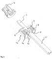
- Figure 6 shows a perspective view of a door lock assembly with two door handles 2, 3 and an overload clutch 12 in the assembled state.
- an electromechanical coupling (not shown here) can be arranged in the free area of the mandrel part 1 '.
- the mandrel part 1 ' can be divided again in the area of the electromechanical coupling.
Landscapes
- Lock And Its Accessories (AREA)
Applications Claiming Priority (1)
| Application Number | Priority Date | Filing Date | Title |
|---|---|---|---|
| DE102004048465 | 2004-10-05 |
Publications (2)
| Publication Number | Publication Date |
|---|---|
| EP1645703A2 true EP1645703A2 (fr) | 2006-04-12 |
| EP1645703A3 EP1645703A3 (fr) | 2010-06-02 |
Family
ID=35717517
Family Applications (1)
| Application Number | Title | Priority Date | Filing Date |
|---|---|---|---|
| EP05021716A Withdrawn EP1645703A3 (fr) | 2004-10-05 | 2005-10-05 | Dispositif de verrouillage de porte et embrayage pour dispositif de verrouillage de porte |
Country Status (1)
| Country | Link |
|---|---|
| EP (1) | EP1645703A3 (fr) |
Cited By (1)
| Publication number | Priority date | Publication date | Assignee | Title |
|---|---|---|---|---|
| DE102006037779A1 (de) * | 2006-08-11 | 2008-02-14 | Hewi Heinrich Wilke Gmbh | Vierkantstift |
Family Cites Families (3)
| Publication number | Priority date | Publication date | Assignee | Title |
|---|---|---|---|---|
| FR960130A (fr) * | 1950-04-13 | |||
| DE10305697B4 (de) * | 2003-02-12 | 2005-03-31 | Karl Simon Gmbh & Co. Kg | Schloss |
| WO2004100082A1 (fr) * | 2003-05-08 | 2004-11-18 | Scott A Mccormack | Piece rapportee de barillet pour une serrure a barillet |
-
2005
- 2005-10-05 EP EP05021716A patent/EP1645703A3/fr not_active Withdrawn
Cited By (1)
| Publication number | Priority date | Publication date | Assignee | Title |
|---|---|---|---|---|
| DE102006037779A1 (de) * | 2006-08-11 | 2008-02-14 | Hewi Heinrich Wilke Gmbh | Vierkantstift |
Also Published As
| Publication number | Publication date |
|---|---|
| EP1645703A3 (fr) | 2010-06-02 |
Similar Documents
| Publication | Publication Date | Title |
|---|---|---|
| DE102014115661B4 (de) | Scharnier mit variabler Reibung | |
| EP3488064B1 (fr) | Dispositif d'entraînement d'un ensemble d'éléments de fermeture | |
| EP1707307B1 (fr) | Système de serrage rapide | |
| EP2098743B1 (fr) | Mécanisme de réglage destiné à l'insertion et l'extraction d'un embrayage de coupure à l'aide d'un segment de came rotatif | |
| DE102019001189B4 (de) | Parksperrensystem für ein Kraftfahrzeug | |
| EP1989960A1 (fr) | Ferrure à cran d'arrêt | |
| DE102014019837B3 (de) | Linearaktor | |
| DE1750278B1 (de) | Vorrichtung zum drehmomentabhaengigen entkuppeln von wellen | |
| EP2410110B1 (fr) | Cylindre de fermeture, notamment cylindre double doté d'un organe de fermeture à roue libre | |
| DE202015106773U1 (de) | Auswerferanordnung für ein bewegbares Möbelteil | |
| DE69704777T2 (de) | Drehmomentbegrenzungskupplung mit einer einzelnd wiederholenden stellung | |
| WO2009000390A1 (fr) | Dispositif de connexion | |
| EP2096027A2 (fr) | Commande de clapets | |
| EP3242985B1 (fr) | Serrure motorisée | |
| EP3665349A1 (fr) | Serrure de porte | |
| DE102017100731A1 (de) | Entriegelungsvorrichtung zum Öffnen einer Tür mit einem Panikschloss, insbesondere ein Touchbar, mit einem Antrieb zum automatischen Öffnen des Panikschlosses | |
| EP1645703A2 (fr) | Dispositif de verrouillage de porte et embrayage pour dispositif de verrouillage de porte | |
| CH669636A5 (fr) | ||
| EP3725992B1 (fr) | Entraînement | |
| EP2213887B1 (fr) | Dispositif de liaison | |
| DE2025396C3 (de) | Verschlußschnalle für einen Sicherheitsgurt, insbesondere von Kraftfahrzeugen | |
| DE102017211709B4 (de) | Türkantenschutzeinrichtung | |
| DE9314325U1 (de) | Flügelscharnier | |
| DE10258083B4 (de) | Türöffner mit Lineargetriebe | |
| DE102013213149A1 (de) | Drehmomentübertragungseinrichtung |
Legal Events
| Date | Code | Title | Description |
|---|---|---|---|
| PUAI | Public reference made under article 153(3) epc to a published international application that has entered the european phase |
Free format text: ORIGINAL CODE: 0009012 |
|
| AK | Designated contracting states |
Kind code of ref document: A2 Designated state(s): AT BE BG CH CY CZ DE DK EE ES FI FR GB GR HU IE IS IT LI LT LU LV MC NL PL PT RO SE SI SK TR |
|
| AX | Request for extension of the european patent |
Extension state: AL BA HR MK YU |
|
| PUAL | Search report despatched |
Free format text: ORIGINAL CODE: 0009013 |
|
| AK | Designated contracting states |
Kind code of ref document: A3 Designated state(s): AT BE BG CH CY CZ DE DK EE ES FI FR GB GR HU IE IS IT LI LT LU LV MC NL PL PT RO SE SI SK TR |
|
| AX | Request for extension of the european patent |
Extension state: AL BA HR MK YU |
|
| AKY | No designation fees paid | ||
| STAA | Information on the status of an ep patent application or granted ep patent |
Free format text: STATUS: THE APPLICATION IS DEEMED TO BE WITHDRAWN |
|
| 18D | Application deemed to be withdrawn |
Effective date: 20101203 |