EP1645764A1 - Fahrzeuglenkvorrichtung - Google Patents
Fahrzeuglenkvorrichtung Download PDFInfo
- Publication number
- EP1645764A1 EP1645764A1 EP04732214A EP04732214A EP1645764A1 EP 1645764 A1 EP1645764 A1 EP 1645764A1 EP 04732214 A EP04732214 A EP 04732214A EP 04732214 A EP04732214 A EP 04732214A EP 1645764 A1 EP1645764 A1 EP 1645764A1
- Authority
- EP
- European Patent Office
- Prior art keywords
- joint
- spherical
- connecting base
- base portion
- intermediate shaft
- Prior art date
- Legal status (The legal status is an assumption and is not a legal conclusion. Google has not performed a legal analysis and makes no representation as to the accuracy of the status listed.)
- Withdrawn
Links
Images








Classifications
-
- B—PERFORMING OPERATIONS; TRANSPORTING
- B62—LAND VEHICLES FOR TRAVELLING OTHERWISE THAN ON RAILS
- B62D—MOTOR VEHICLES; TRAILERS
- B62D1/00—Steering controls, i.e. means for initiating a change of direction of the vehicle
- B62D1/02—Steering controls, i.e. means for initiating a change of direction of the vehicle vehicle-mounted
- B62D1/16—Steering columns
- B62D1/20—Connecting steering column to steering gear
-
- F—MECHANICAL ENGINEERING; LIGHTING; HEATING; WEAPONS; BLASTING
- F16—ENGINEERING ELEMENTS AND UNITS; GENERAL MEASURES FOR PRODUCING AND MAINTAINING EFFECTIVE FUNCTIONING OF MACHINES OR INSTALLATIONS; THERMAL INSULATION IN GENERAL
- F16D—COUPLINGS FOR TRANSMITTING ROTATION; CLUTCHES; BRAKES
- F16D3/00—Yielding couplings, i.e. with means permitting movement between the connected parts during the drive
- F16D3/16—Universal joints in which flexibility is produced by means of pivots or sliding or rolling connecting parts
- F16D3/20—Universal joints in which flexibility is produced by means of pivots or sliding or rolling connecting parts one coupling part entering a sleeve of the other coupling part and connected thereto by sliding or rolling members
- F16D3/22—Universal joints in which flexibility is produced by means of pivots or sliding or rolling connecting parts one coupling part entering a sleeve of the other coupling part and connected thereto by sliding or rolling members the rolling members being balls, rollers, or the like, guided in grooves or sockets in both coupling parts
- F16D3/223—Universal joints in which flexibility is produced by means of pivots or sliding or rolling connecting parts one coupling part entering a sleeve of the other coupling part and connected thereto by sliding or rolling members the rolling members being balls, rollers, or the like, guided in grooves or sockets in both coupling parts the rolling members being guided in grooves in both coupling parts
-
- F—MECHANICAL ENGINEERING; LIGHTING; HEATING; WEAPONS; BLASTING
- F16—ENGINEERING ELEMENTS AND UNITS; GENERAL MEASURES FOR PRODUCING AND MAINTAINING EFFECTIVE FUNCTIONING OF MACHINES OR INSTALLATIONS; THERMAL INSULATION IN GENERAL
- F16D—COUPLINGS FOR TRANSMITTING ROTATION; CLUTCHES; BRAKES
- F16D3/00—Yielding couplings, i.e. with means permitting movement between the connected parts during the drive
- F16D3/16—Universal joints in which flexibility is produced by means of pivots or sliding or rolling connecting parts
- F16D3/20—Universal joints in which flexibility is produced by means of pivots or sliding or rolling connecting parts one coupling part entering a sleeve of the other coupling part and connected thereto by sliding or rolling members
- F16D3/22—Universal joints in which flexibility is produced by means of pivots or sliding or rolling connecting parts one coupling part entering a sleeve of the other coupling part and connected thereto by sliding or rolling members the rolling members being balls, rollers, or the like, guided in grooves or sockets in both coupling parts
- F16D3/223—Universal joints in which flexibility is produced by means of pivots or sliding or rolling connecting parts one coupling part entering a sleeve of the other coupling part and connected thereto by sliding or rolling members the rolling members being balls, rollers, or the like, guided in grooves or sockets in both coupling parts the rolling members being guided in grooves in both coupling parts
- F16D2003/22323—Attachments to the shaft of the inner joint member whereby the attachments are distanced from the core
-
- F—MECHANICAL ENGINEERING; LIGHTING; HEATING; WEAPONS; BLASTING
- F16—ENGINEERING ELEMENTS AND UNITS; GENERAL MEASURES FOR PRODUCING AND MAINTAINING EFFECTIVE FUNCTIONING OF MACHINES OR INSTALLATIONS; THERMAL INSULATION IN GENERAL
- F16D—COUPLINGS FOR TRANSMITTING ROTATION; CLUTCHES; BRAKES
- F16D3/00—Yielding couplings, i.e. with means permitting movement between the connected parts during the drive
- F16D3/16—Universal joints in which flexibility is produced by means of pivots or sliding or rolling connecting parts
- F16D3/20—Universal joints in which flexibility is produced by means of pivots or sliding or rolling connecting parts one coupling part entering a sleeve of the other coupling part and connected thereto by sliding or rolling members
- F16D3/22—Universal joints in which flexibility is produced by means of pivots or sliding or rolling connecting parts one coupling part entering a sleeve of the other coupling part and connected thereto by sliding or rolling members the rolling members being balls, rollers, or the like, guided in grooves or sockets in both coupling parts
- F16D3/223—Universal joints in which flexibility is produced by means of pivots or sliding or rolling connecting parts one coupling part entering a sleeve of the other coupling part and connected thereto by sliding or rolling members the rolling members being balls, rollers, or the like, guided in grooves or sockets in both coupling parts the rolling members being guided in grooves in both coupling parts
- F16D2003/22326—Attachments to the outer joint member, i.e. attachments to the exterior of the outer joint member or to the shaft of the outer joint member
-
- Y—GENERAL TAGGING OF NEW TECHNOLOGICAL DEVELOPMENTS; GENERAL TAGGING OF CROSS-SECTIONAL TECHNOLOGIES SPANNING OVER SEVERAL SECTIONS OF THE IPC; TECHNICAL SUBJECTS COVERED BY FORMER USPC CROSS-REFERENCE ART COLLECTIONS [XRACs] AND DIGESTS
- Y10—TECHNICAL SUBJECTS COVERED BY FORMER USPC
- Y10S—TECHNICAL SUBJECTS COVERED BY FORMER USPC CROSS-REFERENCE ART COLLECTIONS [XRACs] AND DIGESTS
- Y10S464/00—Rotary shafts, gudgeons, housings, and flexible couplings for rotary shafts
- Y10S464/904—Homokinetic coupling
- Y10S464/906—Torque transmitted via radially spaced balls
Definitions
- the present invention relates to a joint apparatus for transmitting rotation between two shafts having different directions, particularly relates to a joint apparatus and a universal ball joint for a vehicular steering.
- a universal joint apparatus is used for transmitting rotation or power between two shafts which are not disposed on a straight line.
- a cross universal joint referred to as a Cardan joint, a hook joint, a cross joint or the like is constituted by coupling two shafts via a cross member having four shaft portions in a cross-like shape. The two shaft portions disposed on sides opposed to each other are supported by yokes of the respective shafts.
- a universal ball joint interposes a torque transmitting ball at guide grooves formed at an inner face of an outer joint member and an outer face of an inner joint member fitted thereto, respectively, to thereby transmit power between two shafts provided with the inner and the outer joint members.
- the cross universal joint is provided with a drawback derived from mechanics that rotation between two shafts is not made an equal velocity when there is an intersecting angle therebetween.
- two sets thereof are used as a pair of combination by interposing anintermediateshaft. Inthiscase, it is necessary to integrate the two sets such that respective intersecting angles thereof are made to be equal to each other and phases in rotational directions of two cross members are set to a predetermined relationship.
- a steering apparatus of a vehicle when vibration from a road face is transmitted to a handle (steering wheel), steering feeling is deteriorated. Therefore,vibration from the road face is devised not to be transmitted to the steering wheel by providing a shock absorber.
- a rubber joint apparatus interposing vibration isolating rubber between the two shafts is used for such a shock absorber as a countermeasure against vibration.
- the rubber joint apparatus is provided at an intermediate shaft of the joint apparatus, a torsional rigidity thereof is comparatively low owing to a structure thereof. Therefore, when the steering wheel is rotated by a strong force, the rubber joint apparatus is significantly twisted.
- the rubber joint apparatus is assembled with the vibration isolating rubber and other parts, and there are large numbers of related many parts, the apparatus is accompanied by considerably large fabrication errors. Owing to the errors, the equal velocity performance which is to be achieved by combining the cross universal joints in consideration of the phases is deteriorated, which amounts to a variation in the transmission torque and a deterioration in the steering feeling. Although the errors are resolved for the time being by promoting accuracy of the rubber joint apparatus and parts related thereto, or selecting combinations of individual parts to integrate (matching), such a countermeasure is not preferable in view of cost.
- the vibration isolating rubber member is provided with a stopper which is operated against a constant amount ormore of torsion, when a stopper angle thereof is reduced in order to promote accuracy, there also poses a problem that it is difficult to achieve a constitution which can be satisfied in view of a vibration isolating function.
- a female joint member is coupled to an input shaft or an output shaft (for example, intermediate shaft) therefor integrally or by a connecting base member integral with the female joint member
- a male joint member is integrally formed with the input shaft or the output shaft therefor.
- a member coupled with the input shaft or the output shaft becomes a male shaft.
- the above-described ball guide groove needs to be subj ected to highly accurate finish grinding (polishing) since the torque transmitting ball is rolled.
- the ball guide groove on a side of the female joint member is formed at inside of an inner space such that the torque transmitting ball and an outer spherical face joint portion of the male joint member are contained to an inner portion thereof.
- the space is formed at an end portion of the input shaft or the output shaft which is integrally solid and therefore, the space is necessarily provided with a bottom portion. That is, a groove having an inner wall face of a bottomed hole needs to be accurately ground. It is not inherently easy to grind the inner wall face of the bottomed hole, further, the groove at inside thereof needs to be accurately ground and therefore, it is a current state that time and cost are taken in grinding the ball guide groove on the side of the female joint member.
- the present invention is an invention which has been carried out in view of the above-described problem and it is a first problem thereof to provide a joint apparatus for a vehicular steering apparatus in which a variation in a steering torque is inconsiderable, a vibration isolating function is excellent and fabrication cost is inexpensive.
- the present invention is an invention which has been carried out in view of the above-described problem and it is a second problem thereof to provide a universal ball joint for a vehicular steering apparatus capable of being coupled with a counterpart of coupling without separately preparing a coupling even when the counterpart of coupling is a shaft (male shaft), constituting a coupling portion on a side of a female joint member and a space of an inner spherical face joint portion by a through hole, and capable of easily grinding a ball guide groove. Further, it is a third problem thereof to provide a universal ball joint at inexpensive cost thereby.
- resolving means of a first aspect of the present invention is a vehicular steering apparatus, a joint apparatus for a vehicular steering apparatus, comprising an input shaft for transmitting rotation from a steering wheel, an intermediate shaft including an upper intermediate shaft, a lower intermediate shaft and a buffer coupling for coupling the upper intermediate shaft and the lower intermediate shaft, an output shaft for driving a steeringmechanismon a side of a vehicle, and universal joints for respectively coupling the input shaft and the upper intermediate shaft as well as the lower intermediate shaft and the output shaft, characterized in that at least one of the universal joints is a constant velocity ball universal joint.
- both of the universal joints are the constant velocity ball universal joints.
- one of the universal joints is the constant velocity ball universal joint and another is a cross universal joint.
- an intersecting angle of the constant velocity ball universal joint is selected to be larger than an intersecting angle of the cross universal joint.
- the buffer coupling is a rubber coupling using rubber as a buffer material.
- resolving means of a sixth aspect of the present invention is a vehicular steering apparatus comprising a male joint member including a first connecting base portion constituting a cylindrical shape and an outer spherical face joint portion provided on an axis line of the first connecting base portion and having a spherical outer face, a female joint member including a second connecting base portion constituting a cylindrical shape and an inner spherical face joint portion provided on an axis line of the second connecting base portion and having a spherical space fitted with the spherical outer face, an outer ball guide groove formed at the spherical outer face of the outer spherical face joint portion, an inner ball guide groove formed at an inner face of the spherical space of the inner spherical face joint portion, a torque transmitting ball guided by the outer ball guide groove and the inner ball guide groove, and a ball retainer for retaining the torque transmitting ball, characterized in that each of the first connecting base portion constituting a cylindrical shape and an outer s
- flanges constituting a pair for fastening are respectively formed on both sides of the slit of each of the first connecting base portion and the second connecting base portion, wherein each pair of the flange is formed coaxially with fastening holes.
- a female serration is formed at an inner face of the cylinder of each of the first connecting base portion and the second connecting base portion.
- an interval between a cylindrical hole of the second connecting base portion and the inner spherical face joint portion is formed with a through hole penetrated coaxially.
- the through hole is attached with a dust preventing cap for preventing dust and dirt from invading inside of the spherical space by passing the cylindrical hole between the cylindrical hole and the spherical space.
- an interval between the male joint member and the female joint member is provided with a dust preventing boot in a cylindrical shape having a flexible fold for preventing dust and dirt from invading inside of the spherical space.
- numeral 1 designates joint apparatus
- numeral 2L, 2U, 2' designate universal ball joints
- numerals 21, 21' designate fasteningbolts
- numeral 22 designates an inner joint portion
- numeral 221 designates a ball guide groove
- numeral 23 designates an outer joint member
- numeral 231 designates a ball guide groove
- numeral 239 designates an outer joint portion
- numeral 24 designates a torque transmittingball
- numeral 25 designates a ball retainer
- numeral 2 6 designates a boot
- numeral 261 designates a coupling cylinder
- numeral 262 designates a rubber bush
- numeral 263 designates a stopper pin
- numeral 264 designates a lateral hole
- numeral 27 designates a shaft hole
- numeral 271 designates a slotting hole
- numeral 272 designates a bolt hole
- numeral 273 designates a clearance hole
- numeral 3 designates an intermediate shaft
- numeral 30 designates
- Fig. 1 is an explanatory view showing a total of a steering mechanism of an automobile to which the present invention is applied.
- the drawing shows a portion upward from the vehicle side steering mechanism 6.
- the steering column 52 is fixed to the vehicle main body 91 such that inclination thereof is adjustable by the adjusting lever 522.
- the wheel shaft 521 is rotatably supported by the steering column 52 to penetrate inside thereof, and the steering wheel 51 is fixed to an upper end of the wheel shaft 521.
- the joint apparatus 1 is coupled to other end, that is, a lower end side of the steering column 52.
- the joint apparatus 1 is provided with the constant velocity ball universal joints 2, 2 on an upper side and a lower side thereof and the intermediate shaft 3 coupling the couplings at a middle thereof.
- the respective universal ball joints 2 are respectively coupled to the wheel shaft 521 and the input shaft 61 of the vehicle body side steering mechanism 6 by the fastening bolts 21.
- Intersecting angles ⁇ and ⁇ are intersecting angles of the constant velocity ball universal joints 2 and angles which are respectively made by center axis lines of the wheel shaft 521 and the input shaft 61 relative to a center axis line of the intermediate shaft 3.
- the intermediate shaft 3 is provided with the buffer coupling 30.
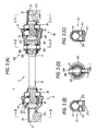
- Fig. 2 illustrates explanatory views of the joint apparatus 1 according to the first embodiment
- Fig.2 (A) is a partially sectional view
- Fig. 2 (B) is a sectional view taken along a line B-B
- Fig.2 (C) is a sectional view taken along a line C-C
- Fig.2 (D) is a sectional taken along a line D-D.
- the joint apparatus 1 is constituted as follows. Both ends of the intermediate shaft 3 are respectively formed with the inner side joint portions 22 constituting portions of the constant velocity ball universal joints 2.
- a vicinity of a front end of the inner joint portion 22 of the constant velocity ball universal joint 2 is formed in a spherical shape, and the ball guide groove 221 is formed with a spherical face thereof.
- the outer joint member 23 is provided with the outer joint portion 239 having a recess portion in a spherical shape, and the ball guide groove 231 is formed the recess portion. Both of the two ball guide grooves 221, 231 are extended along an axial direction of the intermediate shaft 3 and the outer joint member 23, and the inner joint portion 22 and the outer joint member 23 are coupled to each other with regard to rotation by fitting the common torque transmitting ball 24 rollably into the grooves.
- the ball retainer 25 having an inner face complementally with the spherical face of the inner joint portion 22 is made to be rotatable around a center of the spherical face while holding the torque transmitting ball 24.
- the vicinity of a boundary of the inner joint portion 22 and the outer joint portion 239 is covered by the boot 26 constituting a flexible cover to prevent dust and dirt from invading from outside.
- the outer joint members 23 include the shaft holes 27 to be respectively fixed to the wheel shaft 521 and the input shaft 61 of the vehicle body side steering mechanism 6 and the shaft holes 27 are provided with the slotting holes 271.
- the outer joint members 23 are respectively fixed to the wheel shaft 521 and the input shaft 61 by screwing the fastening bolts 21 to the clearance holes 273 and the bolt holes 272 provided on both sides of the slotting holes 271. Operational efficiency can be promoted by providing the clearance holes 273 on the same side of the joint apparatus 1 as shown by Fig. 2 such that operation of fastening the fastening bolts 21 can be carried out from the same direction in integrating to the vehicle body.
- the intermediate shaft 3 according to the first embodiment is split off into the upper intermediate shaft 31 and the lower intermediate shaft 32.
- the rubber coupling 301 shown below is provided as the buffer coupling 30 therebetween. That is, end portions of the upper intermediate shaft 31 and the lower intermediate shaft 32 opposed to each other are respectively formed with the flanges 38 in a shape of an arm.
- the two bolt holes 381 are respectively formed at positions of the respective flanges 38 the same as each other.
- the vibration isolating rubber member 35 in a shape of a circular plate is provided with the four bolt holes 351 in cross directions.
- the two flanges 38 are arranged by shifting phases of the bolt holes 381 of the two flanges 38 alternately by 90 degrees to be opposed to each other by interposing the vibration isolating rubber member 35. Thereby, the four bolt holes 351 of the vibration isolating rubber member 35 and the bolt holes 381 of the respective flanges are aligned on straight lines and the four bolts 352 are respectively passed therethrough to fix.
- the sleeve 354 is fitted to the bolt hole 351 of the vibration isolating rubber member 35 and the spacer 353 in a cylindrical shape is fitted further to a portion of the sleeve 354 projected from the vibration isolating rubber member 35.
- the bolt 352 is inserted into the sleeve 354 and is fastened to fix by the nut 355 along with the stopper 356, mentioned later.
- the upper intermediate shaft 31 and the lower intermediate shaft 32 are coupled by interposing the vibration isolating rubber member 35, metals are not brought into contact with each other and therefore, vibration of the lower intermediate shaft 32 is absorbed by the vibration isolating rubber member 35 to be made difficult to be transmitted to the upper intermediate shaft 31.
- the above-described stoppers 356 are respectively constituted by a shape of a half moon and are fixed at center portions thereof by the above-described bolts 352. Clearances T are respectively formed between the contact sides 357 in correspondence with chords of the half moons of the stopper 356 and the spacers 353.
- the joint apparatus for the vehicular steering apparatus uses two of the constant velocity ball universal joints and therefore, when the couplings and the intermediate shafts are integrated, it is not necessary to carry out complicated phase matching and promote accuracy therefor and cost can be reduced.
- the joint apparatus although the rubber coupling is used, the universal joint is the constant velocity ball universal joint and therefore, a variation in the torque as in using the cross universal joint is not produced and therefore, a feeling of operating the steering wheel is not deteriorated by the variation in the torque. Furthermore, vibration from the vehicle body side is absorbed by the rubber coupling and therefore, operational feeling can be maintained excellently. Further, even when a large torque is applied by steering wheel operation at emergency, the stopper is brought into contact with the spacer and the torque can be transmitted to the lower intermediate shaft and therefore, the safety of the steering apparatus can be promoted also in this respect.
- the joint apparatus 1 according to the second embodiment is provided with the constant velocity ball universal joints 2L, 2U on the upper side and on the lower side and the intermediate shaft 3 connecting the couplings at the middle similar to the first embodiment, a main difference therebetween resides in that with regard to the constant velocity ball universal joint 2U on one side, the relationship between the inner joint portion 22 and the outer joint portion 239 of the first embodiment is reversed and the structure of the buffer coupling 30 differs therefrom.
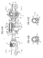
- Fig.3 illustrates explanatory views of the joint apparatus 1 according to the second embodiment
- Fig. 3 (A) is a partially sectional view
- Fig.3 (B) is a sectional view taken along a line B-B
- Fig. 3 (C) is a sectional view taken along a line C-C
- Fig. 3 (D) is a sectional view taken along a line D-D.
- one side (left side of Fig.3) of the intermediate shaft 3 is formed with the inner joint portion 22 constituting a portion of the constant velocity ball universal joint 2L similar to that of the first embodiment, and other side (right side of Fig.3) is formed with the outer joint portion 239.
- a side of the outer joint portion 239 opposed to the recess portion in the spherical shape is provided with the rubber coupling 302 constituting the buffer coupling 30 having a constitution different from that of the first embodiment between the side of the outer joint portion 239 opposed to the recess portion in the spherical shape and the intermediate shaft 3.
- the constitution of the rubber coupling 302 is as follows.
- An inner side of the coupling cylinder 261 integrally formed with the outer joint portion 239 is press-fitted with the rubber bush 262 in a cylindrical shape and an inner side of the rubber bush 2 62 is press-fitted with the upper intermediate shaft 31.
- the upper intermediate shaft 31 is fixed with the stopper pin 263, and the stopper pin 263 is projected into the lateral hole 264 provided at the coupling shaft 261.
- a clearance T is provided between an inner face of the lateral hole 264 and an outer face of the projected portion of the stopper pin 263.
- the outer joint member 23 and the intermediate shaft 3 are coupled via the rubber bush 262 and therefore, when vibration is transmitted from the intermediate shaft 3, the rubber bush 262 is permitted to deform at an interval of the clearance T to operate to absorb vibration. Further, when a large torque is applied, the stopper pin 263 is brought into contact with the inner face of the lateral hole 262 and therefore, the steering torque is firmly transmitted to enable to carry out steering wheel operation safely.
- the joint apparatus for the vehicular steering apparatus uses the two constant velocity ball universal joints and therefore, in integrating the couplings and the intermediate shafts, it is not necessary to carry out complicated phase matching or promote accuracy therefor and the cost can be reduced.
- the joint apparatus although the rubber coupling is used, the universal joint is the constant velocity ball universal joint and therefore, the variation in the torque as in using the cross universal joint is not brought about and therefore, the feeling of operating the steering wheel is not deteriorated by the variation in the torque. Furthermore, vibration from the vehicle body side is absorbed by the rubber coupling and therefore, the operational feeling can excellently be maintained. Further, even when a large torque is applied by steering wheel operation at emergency, the torque can be transmitted by bringing the stopper pin into contact with the inner face of the lateral hole and therefore, safety of the steering apparatus can be promoted also in this respect.
- one of the constant velocityball universal joints according to the first embodiment is substituted for a cross universal joint.
- the output yoke member 44 of the cross universal joint 4 is provided with the shaft hole 47 for fixing to the input shaft 61 of the vehicle body side steering mechanism 6 and the shaft hole 47 is provided with the slotting hole 471.
- the output yoke member 44 is fixed to the input shaft 61 by screwing the fastening bolt 21 to the clearance hole 473 and the bolt hole 472 formed on the both sides of the slotting hole 471.
- the output yoke member 44 is further formed with the second yoke arm pair 43 comprising a pair of arms.
- the cross shaft member 45 is provided with four pieces of shaft portions extended in a cross-like shape and shaft portions on sides opposed to each other are respectively supported axially by the first yoke arm pair 42 and the second yoke arm pair 43.
- the intermediate shaft 3 and the output yoke member 44 are coupled by interposing the cross shaft member 45 to transmit rotation.
- the variation in the torque of the joint apparatus 1 can be reduced, not only an adverse influence can substantially be prevented from being effected on the steering feeling but also the steering feeling can be prevented frombeing deteriorated by absorbing vibration, since the buffer coupling 30 of the rubber coupling 301 or the like is provided.
- the large intersecting angle is assigned to the constant velocity ball universal joint and therefore, the variation in the torque produced at the cross universal joint can be reduced and cost of a total of the joint apparatus can be reduced by using the inexpensive cross universal joint on one side. Further, also in integrating, it is not necessary to carry out complicated phase matching and to promote accuracy therefor, and therefore, the cost can be reduced also in this respect.
- Fig.5 is an explanatory view showing a total of a steering mechanismof an automobile to which a universal ball joint (fourth embodiment) of the present invention is applied.
- the drawing shows a portion upward from the vehicle body side steering mechanism 6.
- the vehicle main body 91 is fixed with the steering column 52 such that inclination thereof is adjustable by the adjusting lever 522.
- the wheel shaft 521 is rotatably supported by the steering column 52 to penetrate inside thereof, and the steering wheel 51 is fixed to an upper portion of the wheel shaft 521.
- the joint apparatus 1 is coupled to other end, that is, the lower end side of the steering column 52.
- the joint apparatus 1 is provided with the constant velocity ball universal joint 2 on the lower side, the constant velocity ball universal joint 2' on the upper side and the intermediate shaft 3 connecting the joints at the middle, and the intermediate shaft 3 is integrally formed with the outer spherical face joint portion of the constant velocity ball universal joint 2'.
- the respective constant velocity ball universal joints 2, 2' are respectively coupled to the wheel shaft 521, the intermediate shaft 3 and the input shaft 61 of the vehicle body side steering mechanism 6.
- the intersecting angles ⁇ and ⁇ are intersecting angles of the constant velocity ball universal joints 2, and are angles made by center axis lines of the wheel shaft 521 and the input shaft 61 relative to the center axis line of the intermediate shaft 3.
- the object of the present invention is shown as the constant velocity ball universal joint 2 on the lower side and an explanation will be given thereof as follows.
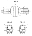
- Fig.6 is a front sectional view of the constant velocity ball universal joint 2 according to the fourth embodiment
- Fig. 7 is a lower side view
- Fig. 4 (A) is a sectional view taken along a line A-A of Fig.6
- Fig.4 (B) is a sectional view taken along a line B-B of the same.
- the male joint member 7 is provided with the first connecting base portion 71 constituting a cylindrical shape, and the outer spherical face joint portion 72 provided on an axis line of the first connecting base portion 71 and having a spherical outer face.
- the female joint member 8 is provided with the second connecting base portion 81 constituting a cylindrical shape, and the inner spherical face joint portion 82 provided on an axis line of the second connecting base portion 81 and having the spherical space 823 fitted with the spherical outer face.
- the spherical outer face of the outer spherical face joint portion 72 is formed with the outer ball guide groove 721 and an inner face of the spherical space 823 of the inner spherical face joint portion 82 is formed with the inner ball guide groove 821, respectively.
- the torque transmitting ball 881 is fitted to the outer ball guide groove 721 and the inner ball guide groove 821, andguidedbytheguidegrooves. Rotation canbe transmitted between the male joint member 7 and the female joint member 8 by three members of the outer ball guide groove 721, the inner ball guide groove 821 and the torque transmitting ball 881, and even when directions of the axis lines of the male joint member 7 and the female joint member 8 differ from each other, a ratio of rotation at this occasion can be maintained constant.
- the ball retainer 882 is fitted to the spherical space 823 from an inner side thereof, further, fitted to the spherical outer face of the outer spherical face joint portion 72 from an outer side thereof, the torque transmitting ball 881 is held at inside of the hole 883 provided at the ball retainer 882 to thereby prevent the torque transmitting ball 881 from being detached from the respective guide grooves.
- the first connecting base portion 71 and the second connecting base portion 81 are provided with the slits 711, 811 having at least one width of 1.5 through 6mm, preferably, 2 through 4mm reaching insides of the respective circular cylinders, and by fastening intervals of the slits, the constant velocity ball universal joint 2 is coupled to male shafts (the input shaft to the constant velocity ball universal joint 2 and the output shaft therefrom) respectively disposed at outside thereof.
- the fastening structure is as follows. That is, both sides of the slits 711, 811 of the first connecting base portion 71 and the second connecting base portion 81 are respectively formed with the flanges 712, 812 constituting pairs for fastening, and the respective pairs of the flanges 712, 812 are coaxially formed with the bolt holes 713, 813 on one side and the clearance holes 714, 814 on other side.
- the bolt hole isM8X1.25or M10X1.2 of JIS.
- the fastening bolts are passed from sides of the clearance holes 714, 814 and screwed to the bolt holes 713, 813.
- the coupling may be produced by a friction force, in order to make the coupling more solid, the female serrations 715, 815 are formed at inner faces of cylinders of the first connecting base portion 71 and the second connecting base portion 81 to be geometrically engaged with male serrations of the male shafts.
- the serrations also coupling by geometrical constraint by shapes of a spline, an elliptical shape, a polygonal shape or the like can also be adopted.
- both of the fastening holes may be constituted by a clearance hole to be fastened by a bolt and a nut.
- the bolt holes 713, 813, and the clearance holes 714, 814 are formed substantially in the same directions, thereby, directions of inserting the bolts 21 become substantially the same, and in integrating to a vehicle, integrating operation is facilitated.
- the inner ball guide groove 821 and the torque transmitting ball 881 not only wear is accelerated but by biting dust and dirt, a very small variation in the torque (rattling feeling) is brought about and therefore, the steering feeling is deteriorated.
- the cylindrical dust preventing boot 95 having flexible folds and made of rubber or resin is provided between the male joint member 7 and the female joint member 8 to cover the portion.
- the cylindrical hole 816 of the second connecting base portion 81 and the spherical space 823 of the inner spherical face joint portion 82 constitute one continuation to thereby form a through hole penetrated coaxially.
- the ball guide grooves 821, 721 need to be subjected to highly accurate finishing grinding (polishing) to roll the torque transmitting ball.
- the inner ball guide groove 821 on the side of the female joint member 8 is formed at inside of the inner space (spherical space 823) to contain the torque transmitting ball 881 and the outer spherical face joint portion 72 of the male joint member 7 at inside thereof.
- the spherical space 823 is bottomed (that is, not penetrated) and therefore, it is very difficult to grind the inner ball guide groove 821 while supplying a grinding solution from one side in the narrow space and simultaneously putting a grindstone thereinto and therefore, it is a current state that time and cost are taken in grinding the inner ball guide groove 821 on the side of the female joint member 8.
- the through hole is formed by the cylindrical hole 816 and the spherical space 823 and therefore, access can be made to the portion to be ground from both sides thereof and therefore, the above-described difficulty is considerably alleviated and time and cost of grinding can be reduced. Further, by penetrating in this way, in working the female serration 815, efficient broaching can be adopted and therefore, the cost can be reduced. Cold forging, hot forging and machining are adopted for the male joint member 7 and the female joint member 8.
- Fig.9 is a front sectional view of the constant velocity ball universal joint 2 according to a fifth embodiment
- Fig.10 (A) is a sectional view taken along a line A-A of Fig.9
- Fig.10 (B) is a sectional view taken along a line B-B of the same.
- the fifth embodiment is an example of making the male joint member 7, the female joint member 8 by hot forging. Since the flange 812 on the side of the female joint member 8 is not provided with a constricted portion between the flange 812 and the inner spherical face joint portion 82, although a weight thereof is slightly increased, there is achieved an advantage that a structure thereof is simple and a total length thereof can be shortened.
- Other of the fifth embodiment is similar to that of the fourth embodiment and therefore, the explanation of the fourth embodiment is referred and a duplicated explanation thereof will be omitted.
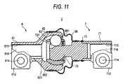
- Fig. 11 is a front sectional view of the constant velocity ball universal joint 2 according to a sixth embodiment.
- the male joint member 7 is constituted by two parts of the first connecting base portion 71 and the outer spherical face joint portion 72 to be fitted to each other and a fitting portion thereof is welded (welded portion 73).
- Other of the sixth embodiment is similar to those of the first and the second embodiments and therefore, the explanation of the first and the second embodiments will be and a duplicated explanation thereof will be omitted.
- the first connecting base portion 71 is produced by cold forging, warm forging, or hot forging and machining.
- Fig. 12 is a front sectional view of the constant velocity ball universal joint 2 according to a seventh embodiment
- Fig.13 is a sectional view taken along a line A-A of Fig.12.
- the male joint member 7 is constituted by two parts of the first connecting base portion 71 and the outer spherical face joint portion 72 to be fitted to each other, and the fitting portion is welded.
- the first connecting base portion 71 is fabricated by a plate member and portions of the respective flanges 712 are folded back.
- the dust preventing cap 96 partitioning the cylindrical hole 816 and the spherical space 823 is provided.
- the dust preventing cap 96 also prevents grease at inside of the spherical space 823 from flowing out.
- the dust preventing cap 96 can be adopted not only for the embodiment but also other embodiments in which the cylindrical hole 816 and the spherical space 823 are continuous to form the through hole.
- Other of the seventh embodiment is similar to those of the above-described embodiments and therefore, the explanation of the other embodiments will be referred and a duplicated explanation thereof will be omitted.
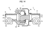
- Fig. 14 is a front sectional view of the constant velocity ball universal joint 2 according to an eighth embodiment.
- a portion of the dust preventing boot 95 is opened.
- a boot having such a structure is frequently sufficient.
- the dust preventing boot 95 is only brought into slightly contact with an outer side of the inner spherical face joint portion 82 or is not brought into contact therewith at all and therefore, there is achieves an advantage that a load torque (fold-bend torque) having a magnitude as in completely enclosing the constant velocity ball universal joint 2 is not generated.
- the dust preventing boot 95 can also be provided to the side of the inner spherical face j oint portion 82.
- Other of the eighth embodiment is similar to those of the above-described embodiments and therefore, the explanation of the other embodiments will be referred and the duplicating explanation thereof will be omitted.
- the joint apparatus of the present invention it is not necessary to carry out complicated phase matching in integrating operation and promote accuracy therefor and therefore, not only the cost can be reduced but also the feeling of operating the steeringwheel is not deteriorated by a variation in the torque since large variation in the torque as in using only the cross universal joint is not generated because the constant velocity ball universal joint is used for the universal joint while using the rubber coupling. Further, vibration from the vehicle body side is absorbed by the rubber coupling and therefore, the operational feeling can be maintained excellent. Further, even when a large torque is applied by steering wheel operation at emergency, the torque can be transmitted by operating the stopper and therefore, safety of the steering apparatus can be promoted.
- the constant velocity ball universal joint of the present invention can be coupled to a counterpart of coupling without separately preparing a coupling even when the counterpart of coupling is a shaft (male shaft), further, the joint portion on the side of the female joint member and the space of the inner spherical face joint portion constitute the through hole and therefore, there is achieved an effect of capable of comparatively easily grinding the ball guide groove. Further, thereby, there is achieved an effect of capable of providing the constant velocity ball universal joint at inexpensive cost.
Landscapes
- Engineering & Computer Science (AREA)
- General Engineering & Computer Science (AREA)
- Mechanical Engineering (AREA)
- Chemical & Material Sciences (AREA)
- Combustion & Propulsion (AREA)
- Transportation (AREA)
- Steering Controls (AREA)
Applications Claiming Priority (3)
| Application Number | Priority Date | Filing Date | Title |
|---|---|---|---|
| JP2003195986A JP2005028996A (ja) | 2003-07-11 | 2003-07-11 | 車両ステアリング装置用の軸継手装置 |
| JP2003199536A JP2005036865A (ja) | 2003-07-18 | 2003-07-18 | 車両ステアリング装置用の等速ボール自在継手 |
| PCT/JP2004/006607 WO2005005850A1 (ja) | 2003-07-11 | 2004-05-11 | 車両ステアリング装置 |
Publications (2)
| Publication Number | Publication Date |
|---|---|
| EP1645764A1 true EP1645764A1 (de) | 2006-04-12 |
| EP1645764A4 EP1645764A4 (de) | 2007-08-22 |
Family
ID=34067344
Family Applications (1)
| Application Number | Title | Priority Date | Filing Date |
|---|---|---|---|
| EP04732214A Withdrawn EP1645764A4 (de) | 2003-07-11 | 2004-05-11 | Fahrzeuglenkvorrichtung |
Country Status (3)
| Country | Link |
|---|---|
| US (1) | US7429216B2 (de) |
| EP (1) | EP1645764A4 (de) |
| WO (1) | WO2005005850A1 (de) |
Cited By (3)
| Publication number | Priority date | Publication date | Assignee | Title |
|---|---|---|---|---|
| EP1760347A1 (de) * | 2005-08-30 | 2007-03-07 | Ntn Corporation | Welle für Gleichlaufgelenk |
| DE102007011661A1 (de) * | 2007-03-09 | 2008-09-11 | Zf Lenksysteme Gmbh | Lenkwelle |
| EP2172666A4 (de) * | 2007-06-29 | 2017-07-05 | NTN Corporation | Gelenk für lenkung |
Families Citing this family (6)
| Publication number | Priority date | Publication date | Assignee | Title |
|---|---|---|---|---|
| JP2006199249A (ja) * | 2005-01-24 | 2006-08-03 | Nsk Ltd | ステアリング装置 |
| US20150123391A1 (en) * | 2013-11-04 | 2015-05-07 | Readylift Suspension, Inc. | Steering correction and support device and methods of making and using same |
| JP6156113B2 (ja) * | 2013-12-12 | 2017-07-05 | 株式会社ジェイテクト | シャフトと自在継手との結合構造 |
| JP6174775B1 (ja) * | 2016-03-31 | 2017-08-02 | 東芝機械株式会社 | シート・フィルム成形ロール装置、シート・フィルム成形方法 |
| JP6311054B1 (ja) | 2017-07-20 | 2018-04-11 | 東芝機械株式会社 | 両面転写式シート・フィルム成形ロール装置、両面転写式シート・フィルム成形方法 |
| JP6512388B1 (ja) | 2017-10-19 | 2019-05-15 | 日本精工株式会社 | 伸縮リンク及びサスペンション |
Family Cites Families (15)
| Publication number | Priority date | Publication date | Assignee | Title |
|---|---|---|---|---|
| US2325460A (en) * | 1940-09-20 | 1943-07-27 | Walter E Amberg | Constant velocity universal joint |
| GB1288745A (de) * | 1968-10-11 | 1972-09-13 | ||
| US4685897A (en) * | 1985-02-22 | 1987-08-11 | Gkn Automotive Components Inc. | Universal joint for tilt steering wheel |
| JPH0325445Y2 (de) | 1985-07-22 | 1991-06-03 | ||
| JPH0743494Y2 (ja) | 1987-08-21 | 1995-10-09 | 日本精工株式会社 | 弾性軸継手 |
| DE4306121C2 (de) * | 1993-02-27 | 2000-09-21 | Man Nutzfahrzeuge Ag | Umlenkeinrichtung zur Übertragung des vom Lenkrad eingeleiteten Radlenkausschlages bei Nutzfahrzeugen |
| JP3536296B2 (ja) * | 1999-01-22 | 2004-06-07 | トヨタ自動車株式会社 | 車両用操舵制御装置 |
| JP4157213B2 (ja) * | 1999-03-03 | 2008-10-01 | 株式会社ジェイテクト | 自在継手におけるヨークとシャフトとの連結構造 |
| JP4219468B2 (ja) | 1999-03-04 | 2009-02-04 | Ntn株式会社 | 等速自在継手 |
| JP4219472B2 (ja) | 1999-03-12 | 2009-02-04 | Ntn株式会社 | 等速自在継手 |
| JP2001199352A (ja) * | 2000-01-18 | 2001-07-24 | Nsk Ltd | 車両用ステアリング装置 |
| JP2002144155A (ja) | 2000-11-14 | 2002-05-21 | Takehiko Watanabe | 液体中での超音波振動付加による引張残留応力の除去方法 |
| US6579187B2 (en) * | 2001-04-30 | 2003-06-17 | Gkn Automotive, Inc. | Shield for use in a constant velocity joint |
| JP4245849B2 (ja) | 2001-06-08 | 2009-04-02 | Ntn株式会社 | プロペラシャフト用等速自在継手 |
| JP4219583B2 (ja) | 2001-10-26 | 2009-02-04 | Ntn株式会社 | 固定型等速自在継手 |
-
2004
- 2004-05-11 US US10/563,831 patent/US7429216B2/en not_active Expired - Fee Related
- 2004-05-11 EP EP04732214A patent/EP1645764A4/de not_active Withdrawn
- 2004-05-11 WO PCT/JP2004/006607 patent/WO2005005850A1/ja not_active Ceased
Cited By (4)
| Publication number | Priority date | Publication date | Assignee | Title |
|---|---|---|---|---|
| EP1760347A1 (de) * | 2005-08-30 | 2007-03-07 | Ntn Corporation | Welle für Gleichlaufgelenk |
| US7568977B2 (en) | 2005-08-30 | 2009-08-04 | Ntn Corporation | Shaft for constant velocity universal joint |
| DE102007011661A1 (de) * | 2007-03-09 | 2008-09-11 | Zf Lenksysteme Gmbh | Lenkwelle |
| EP2172666A4 (de) * | 2007-06-29 | 2017-07-05 | NTN Corporation | Gelenk für lenkung |
Also Published As
| Publication number | Publication date |
|---|---|
| EP1645764A4 (de) | 2007-08-22 |
| US7429216B2 (en) | 2008-09-30 |
| US20060223641A1 (en) | 2006-10-05 |
| WO2005005850A1 (ja) | 2005-01-20 |
Similar Documents
| Publication | Publication Date | Title |
|---|---|---|
| EP3257725B1 (de) | Teleskopische lenksäule und lenkvorrichtung | |
| JP3864885B2 (ja) | 2つの伸縮式のシャフトを回転結合するシステム | |
| US10569802B2 (en) | Vehicle steering system | |
| EP1593581A1 (de) | Lenkvorrichtung für kraftfahrzeug | |
| EP3257721B1 (de) | Teleskopische lenkvorrichtung | |
| EP3257722A1 (de) | Lenkvorrichtung | |
| US7429216B2 (en) | Vehicle steering device | |
| KR20160133968A (ko) | 전동식 동력 보조 조향장치의 감속기 | |
| US6364778B1 (en) | Axially adjustable steering shaft assembly with ball spline | |
| EP1637433A1 (de) | Kraftfahrzeuglenkvorrichtung | |
| CN111727147A (zh) | 用于汽车的、尤其是乘用车的转向系统的转向轴,以及汽车 | |
| CN100451370C (zh) | 车辆转向装置 | |
| KR20090117128A (ko) | 자동차용 인터미디에이트 샤프트 | |
| US7604428B2 (en) | Mounting assembly for drive shafts in universal joint yokes | |
| JP2022085813A (ja) | 中間シャフト | |
| JP4070567B2 (ja) | 弾性自在継手 | |
| JP2005036865A (ja) | 車両ステアリング装置用の等速ボール自在継手 | |
| JPH1019054A (ja) | 弾性継手 | |
| KR20090118621A (ko) | 자동차용 인터미디에이트 샤프트 | |
| JPH08200382A (ja) | 弾性自在継手 | |
| CN108357561B (zh) | 长度可调的转向传动轴组件 | |
| US6250333B1 (en) | Servovalve | |
| KR20190034926A (ko) | 자동차용 조향축 | |
| KR20250171568A (ko) | 차량용 드라이브 샤프트 어셈블리 장착 구조 | |
| JP2007099054A (ja) | 車両用操舵装置 |
Legal Events
| Date | Code | Title | Description |
|---|---|---|---|
| PUAI | Public reference made under article 153(3) epc to a published international application that has entered the european phase |
Free format text: ORIGINAL CODE: 0009012 |
|
| 17P | Request for examination filed |
Effective date: 20060103 |
|
| AK | Designated contracting states |
Kind code of ref document: A1 Designated state(s): DE FR GB |
|
| DAX | Request for extension of the european patent (deleted) | ||
| RBV | Designated contracting states (corrected) |
Designated state(s): DE FR GB |
|
| A4 | Supplementary search report drawn up and despatched |
Effective date: 20070725 |
|
| 17Q | First examination report despatched |
Effective date: 20080709 |
|
| STAA | Information on the status of an ep patent application or granted ep patent |
Free format text: STATUS: THE APPLICATION IS DEEMED TO BE WITHDRAWN |
|
| 18D | Application deemed to be withdrawn |
Effective date: 20081120 |